
01
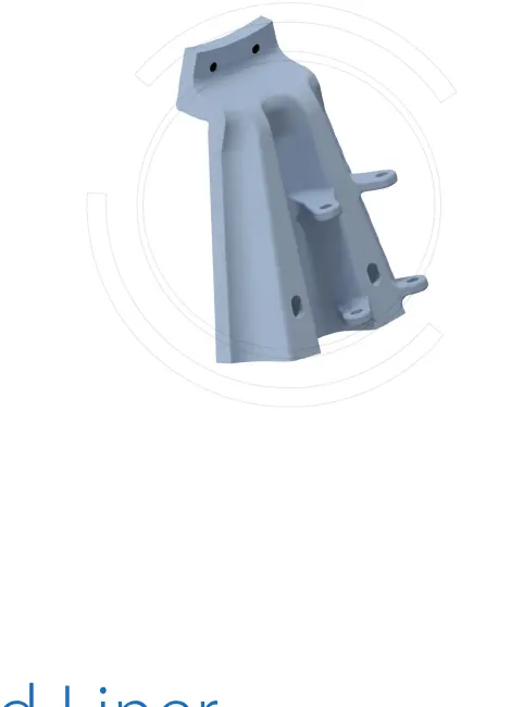
Feed Throat Liners
Feed Chute / Throat Liner
These withstand direct coarse-ore impact and sliding wear. Check inlet profile, flange interface, hole pattern and clearance to the feed chute.
View Part Details →Identify wear parts and spares by installed dimensions, support and drive configuration, then review part positions, materials, drawing and enquiry requirements on one page.
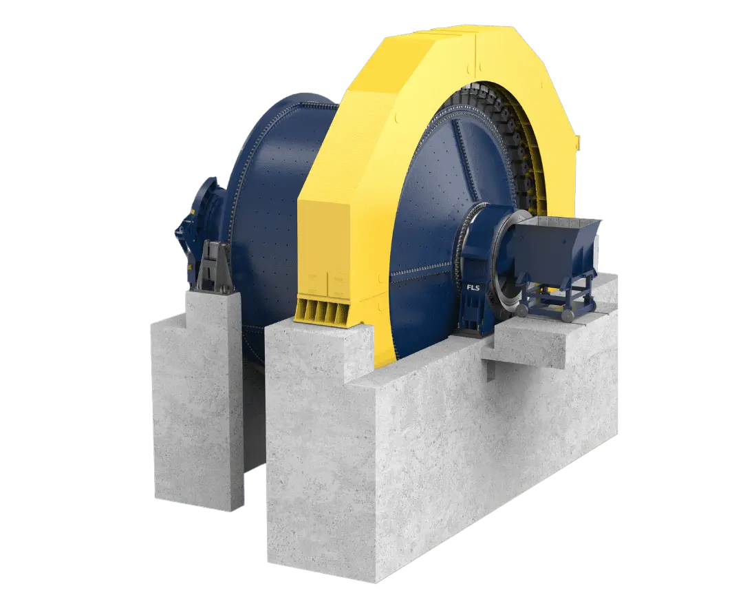
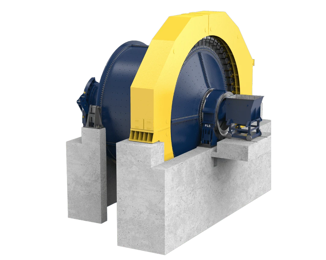
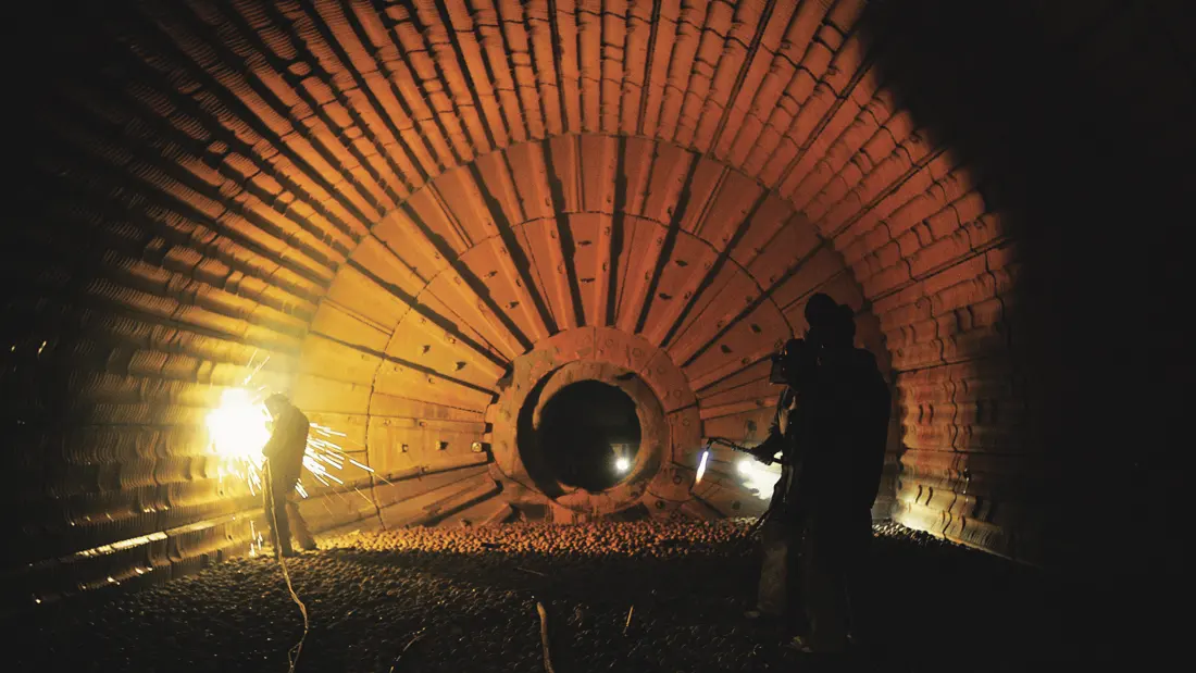
The current published Fuller-Traylor SAG/AG mill range has diameters of 4.3–12.2 m and installed power up to 28,000 kW. Spare identification also requires effective length, serial number, general arrangement drawing, support and drive configuration.
This FLS family is identified by project dimensions and configuration. Only official published ranges are listed; independent model codes are not invented.
| Series / configuration | Officially published dimensions or parameters | Key spare identification checks |
|---|---|---|
| Fuller-Traylor SAG Mill | Diameter 4.3–12.2 m; installed power up to 28,000 kW; ball charge 6–15% | Diameter × effective length, serial number, feed/discharge direction, liner segmentation and drive configuration |
| Fuller-Traylor AG Mill | Within the same published 4.3–12.2 m diameter range; autogenous grinding uses ore without steel ball media | Diameter × effective length, serial number, discharge method, liner system and support structure |
| Support arrangement | Trunnion-supported or shell-supported | General arrangement drawing, foundation interfaces, bearing type and journal or shell load-bearing structure |
| Drive type | High-speed geared, low-speed direct or gearless drives; gear-driven arrangements may use single or dual pinions, with published single-pinion references up to 10,000 kW | Girth gear, pinion, drive shaft, coupling, reducer or ring motor interfaces |
| Discharge configuration | Trommel or vibrating screen; published FLS AG/SAG trommel diameters reach 6.0 m | Discharge grates, pulp lifters, discharge cone, trommel interfaces and rotation direction |
The numbers on the diagram correspond one to one with the rows below.
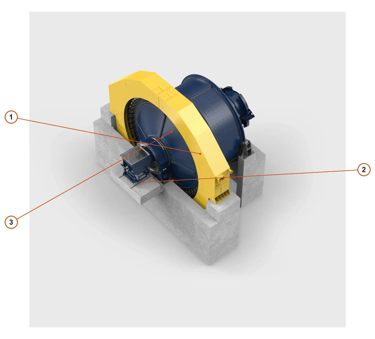
| No. | Component | Location | Applies to |
|---|---|---|---|
| 1 | Mill shell | Central rotating shell | OEM pictured design version; other installations may differ |
| 2 | Feed chute | Feed inlet at the front of the illustrated mill | OEM pictured design version; other installations may differ |
| 3 | Drive guard | Yellow drive guard around the shell | OEM pictured design version; other installations may differ |
Impact, abrasion and slurry erosion differ between positions within the same mill. Cards identify positions and candidate materials; confirm final requirements against installation drawings, drawing, hole patterns and operating conditions.
Feed Chute / Throat Liner
These withstand direct coarse-ore impact and sliding wear. Check inlet profile, flange interface, hole pattern and clearance to the feed chute.
View Part Details →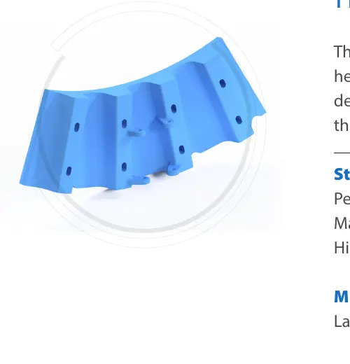
Inner Feed Head Liner
These protect the inside of the feed head against combined ore impact, abrasion and slurry erosion. Confirm segment boundaries and thickness against installation drawings.
View Part Details →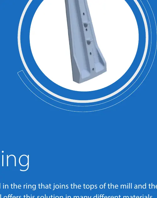
Outer Feed Head Liner
These cover high-impact areas around the outer feed head ring. Check installation relationships together with inner head liners, shell liners and fasteners.
View Part Details →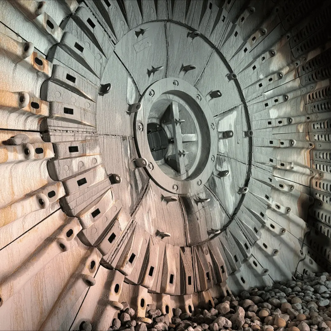
Shell Liner & Lifter Bar
These control the charge lifting trajectory and protect the shell. Profiles, lift height, segmentation and bolt hole patterns directly affect grinding and liner life.
View Part Details →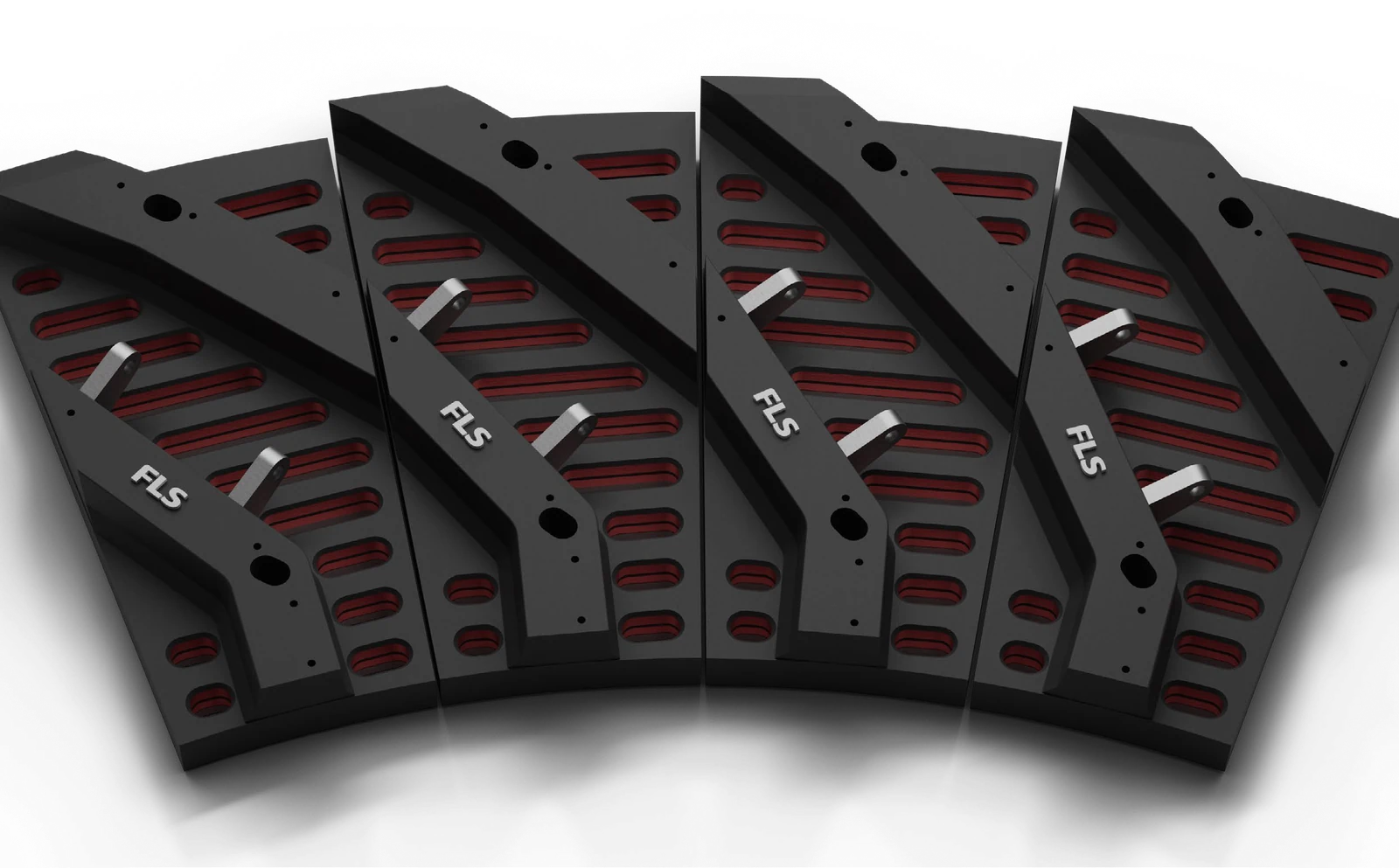
Discharge Grate
Grates control discharge passages and withstand slurry erosion, ore impact and blockage loads. Opening shape, open area and rear support must be compatible.
View Part Details →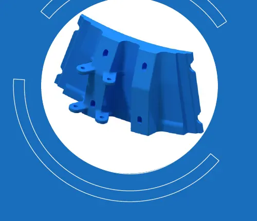
Discharge Middle Liner
These connect the grate and end liner systems. Check radial position, adjacent overlaps, fastening direction and wear allowance.
View Part Details →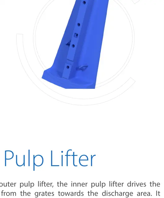
Outer Pulp Lifter
These direct slurry passing through the grates toward the discharge passage. Flow cross-section, rotation direction and adjacent grate positions must match the installation.
View Part Details →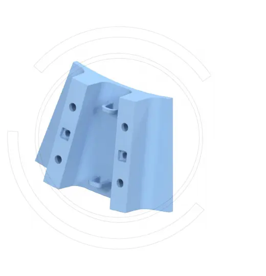
Inner Pulp Lifter
Located inside the discharge system, these transport slurry and control backflow. Check flow direction, blade height and assembly sequence.
View Part Details →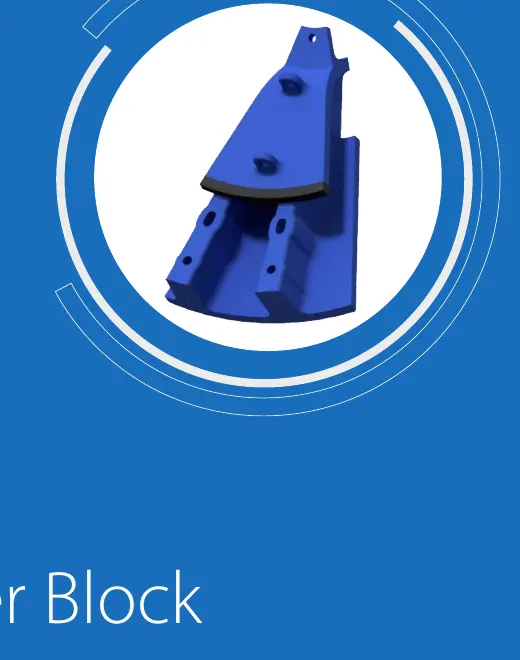
Discharge Cone
These connect pulp lifters to the discharge trunnion passage. Check cone profile, segmentation, flange hole patterns and discharge direction.
View Part Details →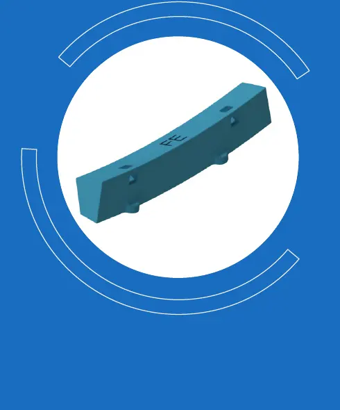
Filler Ring & Sealing Liner
These fill gaps, cushion and seal within the liner system. Match compression, groove profile, fluid and adjacent metal part dimensions.
View Part Details →Gear drives, trunnion support and shell support require different spares. Establish individual matches after receiving the full installed model, serial number, general arrangement drawing and OEM or drawing.
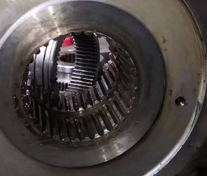
Pinion
For gear-driven configurations. Check tooth count, module, pressure angle, helix angle, journals, tooth accuracy and heat treatment together with the girth gear.
View Part Details →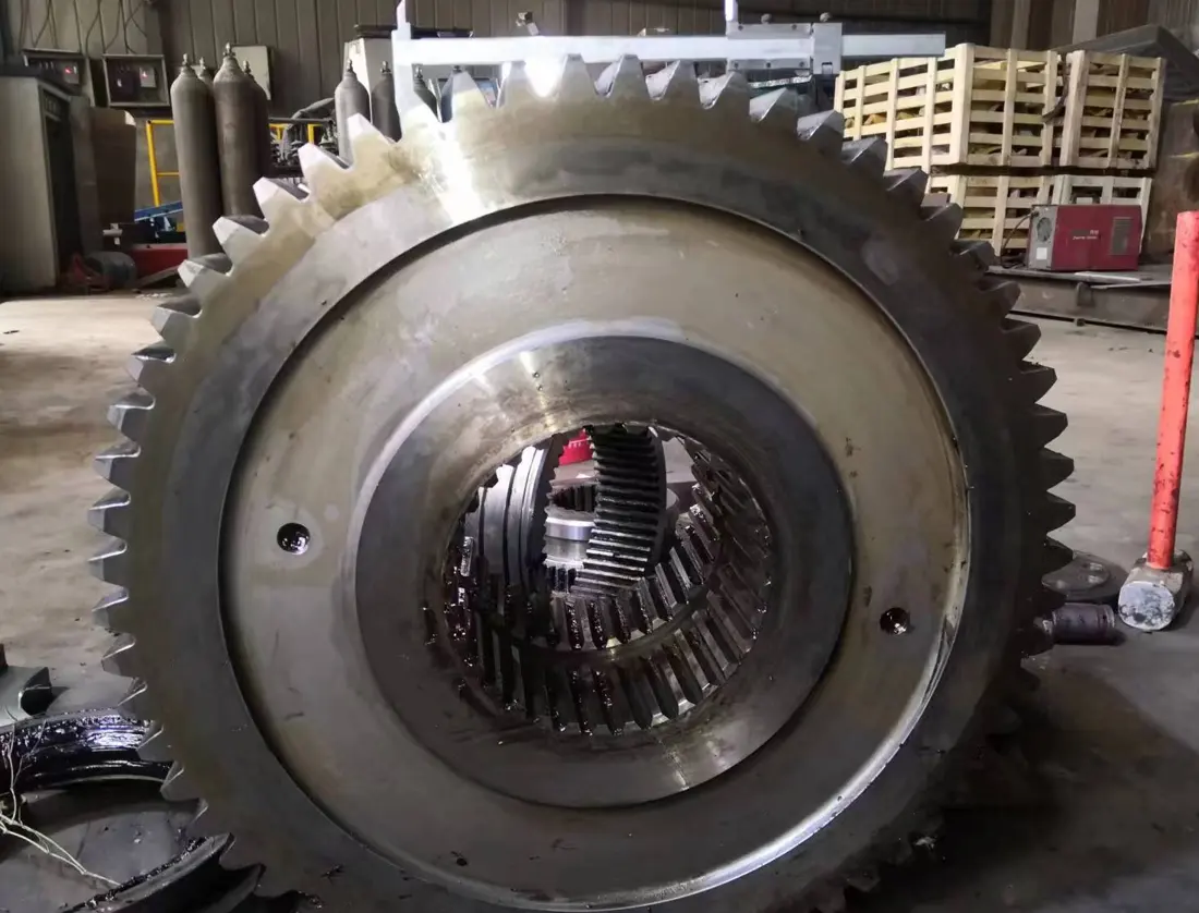
Girth Gear / Ring Gear
For single- or dual-pinion drives. Confirm split joints, tooth geometry, runout, mating marks and installation datums as a system.
View Part Details →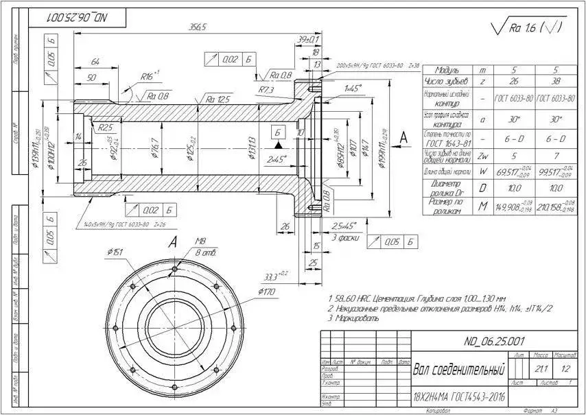
Mill Trunnion
These carry loads and provide feed/discharge interfaces on trunnion-supported mills. Check flanges, journals, bores, fillets, concentricity and bearing fits against the general arrangement drawing.
View Part Details →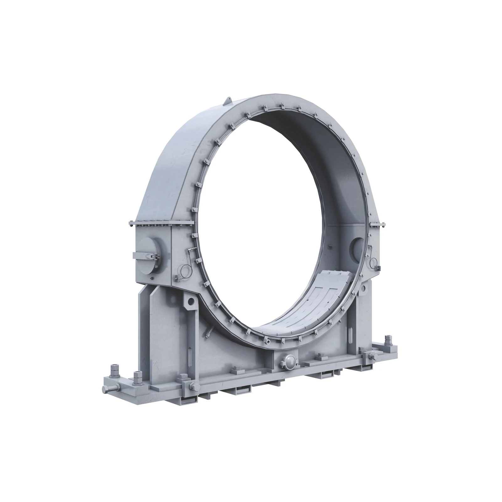
Trunnion Bearing & Bearing Bush
For sliding bearing configurations. Check journal diameter, bearing surface radius, oil grooves, temperature measurement holes, and Babbitt layers or copper alloy structure.
View Part Details →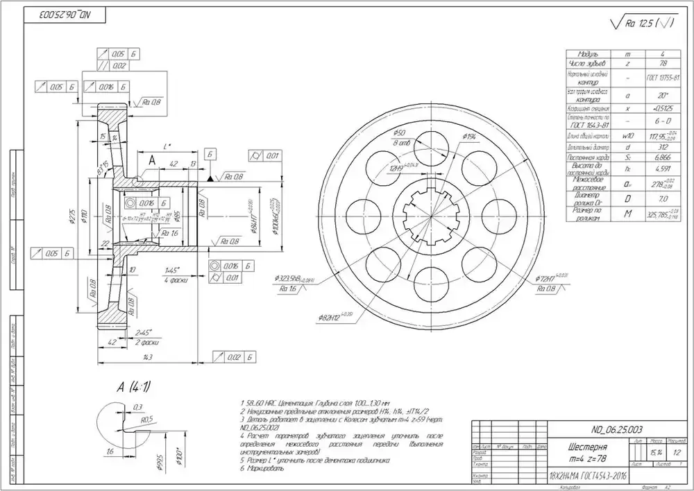
Heavy-Duty Drive Components
These include drive shafts, couplings, reducer interfaces, shaft sleeves and fasteners. Identify them separately for high-speed geared, low-speed direct or gearless drives.
View Part Details →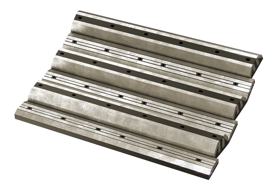
Liner Fastener & Seal Set
These include liner bolts, nuts, washers, gaskets and associated clamping parts. Confirm bolt grade, length, head type and hole positions together with the liners.
Submit Drawings and Numbers →Use the equipment nameplate, serial number, mill diameter and effective length, support arrangement, drive configuration and general arrangement drawing together. Appearance alone is insufficient.
Start by submitting the drawing, matching equipment model, installation position, used-part photos and critical dimensions. These support checks against drawing, the BOM and installation drawings.
Not necessarily. Feed end, shell, discharge end and pulp discharge systems operate under different conditions. Confirm material and structure separately by position, failure mode and original design.
Provide diameter × effective length, support and drive arrangements, serial number, installation position, OEM/drawing, used-part photos, drawings and operating conditions. We use these to identify parts, assess materials, match manufacturing requirements, control quality and deliver finished components.
Or contact us directly: +86 156 3797 3199
zzx@anranst.com
ANRANST provides customers worldwide with engineering assessment, production at certified foundries to the customer technical requirements, quality control and finished-part delivery for custom wear parts and industrial spares, with scope to support other custom industrial parts.
We review mating surfaces and interface dimensions and assess material, heat treatment and manufacturing feasibility.
Material grades and heat-treatment processes are specified order by order, stated in the technical agreement and tracked through production.
Drawing confirmation, material and process control, production tracking, inspection and acceptance coordination.
We coordinate manufacturing, quality confirmation, packaging and delivery of complete finished parts in a workable, closed-loop supply process.
Provide the existing model, drawings, drawing, materials or operating conditions so we can identify the appropriate technical review and supply route.
Submit an Enquiry