FLS DRC Double Roll Crushers

Start with the four standard models and key dimensions to identify crushing teeth, roll shells, side and bottom liners, roll shafts, bearings, hydraulics and drive spares, then confirm materials and drawing numbers for an enquiry.

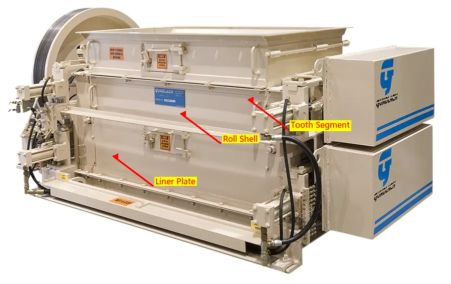
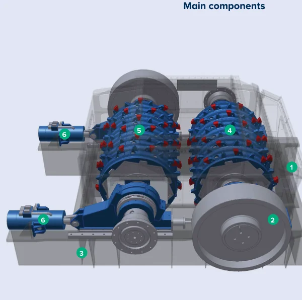
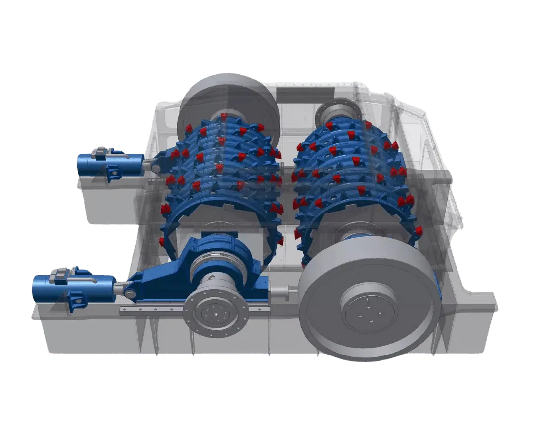
Official FLS DRC double roll crusher internal structure
Official FLS DRC structural image, showing the fixed roll, floating roll, crushing teeth, flywheels, hydraulic relief and frame positions.
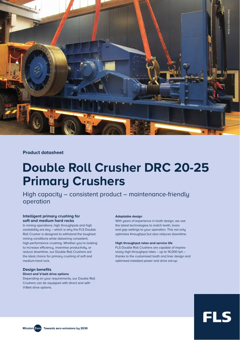
First page of the official FLS DRC 20-25 datasheet
First page of the official FLS DRC 20-25 datasheet. The model table lists product size, capacity, roll diameter and length, feed opening, gap and power.
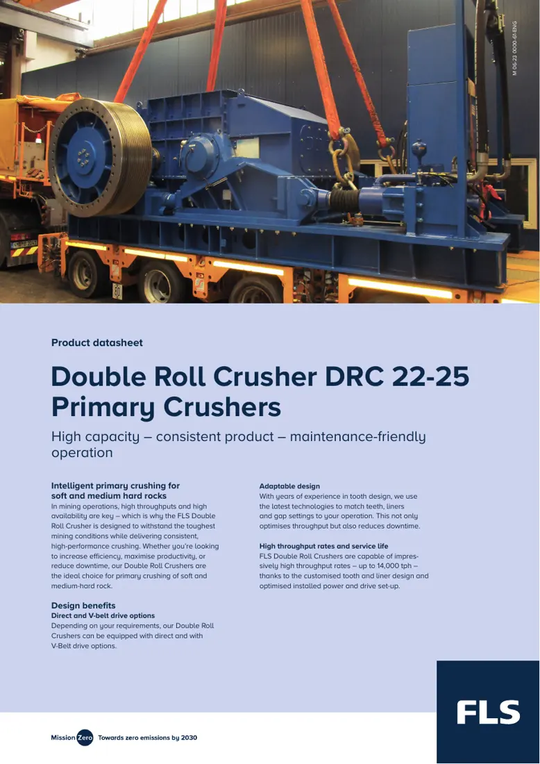
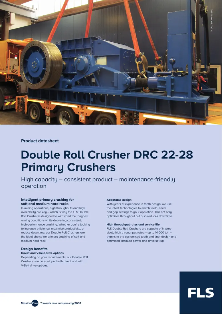
First page of the official FLS DRC 22-28 datasheet
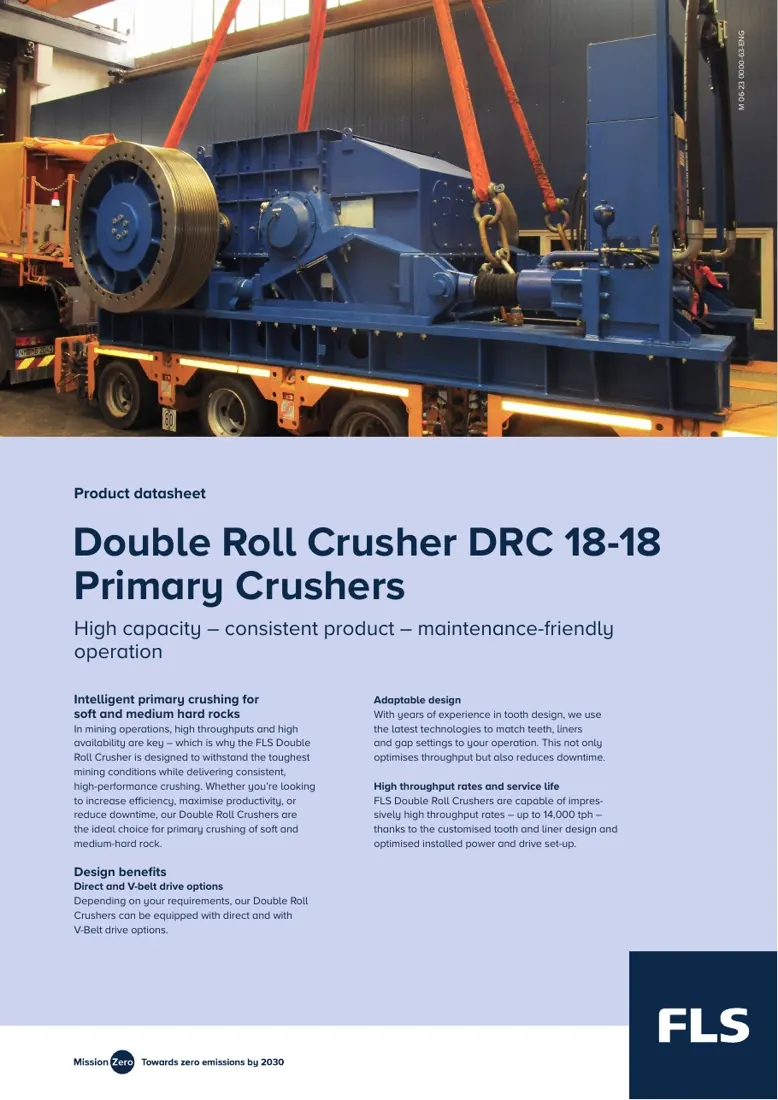
First page of the official FLS DRC 22-28 datasheet. The same series also includes 18-18, 20-25 and 22-25.
OEM Equipment Details

Models, wear parts, spares and materials on one page

DRC performs primary crushing with a fixed roll and a hydraulically yielding floating roll. This page covers the models, dimensions, installation positions, material selection, drawing checks and enquiry information directly needed for spare identification.

4 Published standard models
5 Wear parts
5 Core spares
5 Official sources
Standard Models and Key Dimensions

DRC 18-18 to DRC 22-28

Product size, capacity, toothed roll diameter, roll length, feed opening, adjustable gap and drive power come from the corresponding official FLS datasheets.

ModelProduct sizeCapacityToothed roll diameterRoll lengthFeed openingAdjustable crushing gapMotor power
DRC 18-180–300 mm2,500–4,000 t/hApproximately 1,800 mmApproximately 1,800 mmApproximately 1,700 × 1,850 mmApproximately 200–350 mm2 × 250 kW
DRC 20-250–400 mm4,000–6,000 t/hApproximately 2,000 mmApproximately 2,500 mmApproximately 2,500 × 2,200 mmApproximately 200–400 mm2 × 450 kW
DRC 22-250–400 mm5,000–7,000 t/hApproximately 2,300 mmApproximately 2,500 mmApproximately 2,500 × 2,600 mmApproximately 250–450 mm2 × 650 kW
DRC 22-280–500 mm6,000–8,000 t/hApproximately 2,300 mmApproximately 2,800 mmApproximately 2,900 × 3,100 mmApproximately 250–450 mm2 × 650 kW

Capacity depends on bulk density, strength, size distribution, moisture, target product size and actual gap. Confirm final spares against the full model, serial number, drawing number, drawing revision and installation dimensions.

Wear Parts

Crushing teeth, roll shells, side liners, bottom liners and scrapers

Start with crushing teeth and roll shells, then review sidewall, bottom and cleaning positions. Each item links to the relevant part and material pages.

Crushing tooth and cap position reference in the FLS DRC
01

Crushing Teeth / Tooth Caps

Crushing Teeth / Tooth Caps

Located around both rolls, these directly contact the feed. Check fixed or floating roll, tooth profile and height, pitch, layout, rotation direction, connections, actual gap and used-part wear profile.

Material and manufacturing checks:Select high-manganese steel, wear-resistant alloy steel, carbide-reinforced or composite wear solutions according to feed strength, impact, abrasion and target service life.

View Part Details →
Roll sleeve and shell position reference in the FLS DRC
02

Roll Sleeves / Roll Shells

Roll Shell / Roller Sleeve

These form the wear-resistant outer surfaces and tooth seat foundations of the fixed and floating rolls. Check diameter, length, shaft bore or locking assembly interface, segmentation, locating structure, weight and dynamic balance.

Material and manufacturing checks:Use wear-resistant alloy steel or a combined structure confirmed by the original design. Confirm material, heat treatment, concentricity, radial runout and fit tolerances against drawings.

View Part Details →
Side liner and end guard position reference in the FLS DRC
03

Side Liners / End Guards

Side Liner / Side Plate

These protect roll ends and chamber sides, control material bypass and maintain working clearances. Check left/right side, plate shape, thickness, hole pattern, roll end clearance and adjacent liner overlaps.

Material and manufacturing checks:Confirm quenched and tempered wear plate, wear-resistant cast steel or bimetallic composite plate according to impact, sliding wear and plate thickness.

View Part Details →
Bottom liner position reference in the FLS DRC
04

Bottom Liners

Bottom Liner

These protect the frame and discharge area below the rolls. Check discharge direction, plate thickness, segment numbers, hole patterns, overlaps, blockage clearance and site replacement access.

Material and manufacturing checks:Confirm quenched and tempered wear plate, bimetallic composite plate or wear-resistant cast steel according to drop height, particle size and flow direction.

View Part Details →
Scraper and cleaning blade position reference in the FLS DRC
05

Scrapers / Cleaning Blades

Scraper / Cleaner Blade

Located near the roll surfaces, these limit wet, sticky material buildup. Check installation side, blade profile, roll clearance, length, brackets, wear allowance and adjustment range.

Material and manufacturing checks:Confirm wear plate, elastomers or combined scraper designs according to material adhesion, roll surface structure, temperature and impact.

View Part Details →
Spare Parts

Roll shafts, bearings, hydraulics, drives and adjustment parts

Parts with the same name are not interchangeable by appearance across DRC models or between fixed and floating rolls. Check drawing number, fits, rotation direction, loads, materials and heat treatment.

Fixed and floating roll shaft positions in the FLS DRC
01

Fixed and Floating Roll Shafts

Fixed and Floating Roll Shafts

The two shafts connect the fixed roll and hydraulically yielding floating roll respectively. Check shaft and journal diameters, roll body interfaces, keys/locking assemblies, bearing housing spacing, rotation direction, concentricity and dynamic balance.

Material and manufacturing checks:Confirm forged transmission alloy steel, heat treatment, journal accuracy and non-destructive testing against original drawings and loads.

View Part Details →
Bearing and housing positions in the FLS DRC
02

Bearings and Bearing Housings

Bearing and Bearing Housing

Bearings support fixed and floating rolls under crushing impact. Check bearing model, clearance, journals, housing bores, locating/floating end, seals, lubrication and temperature monitoring interfaces.

Material and manufacturing checks:Confirm rolling bearings, steel housings and seal materials separately according to radial load, impact, speed, temperature rise and lubrication conditions.

View Part Details →
Hydraulic relief and gap adjustment system in the FLS DRC
03

Hydraulic Relief and Gap Adjustment Systems

Hydraulic Relief and Gap Setting System

During overload or tramp metal entry, hydraulics allow the floating roll to yield and also adjust the working gap. Check cylinder bore, stroke, pressure, mounting trunnions, valve blocks, accumulators, ports and seals.

Material and manufacturing checks:Confirm hydraulic cylinder alloy steel, surface treatment and NBR, HNBR, FKM or polyurethane seals according to pressure, fluid and temperature.

View Part Details →
Drive, gearbox and coupling positions in the FLS DRC
04

Drives, Gearboxes and Couplings

Drive, Gearbox and Coupling

FLS DRC can use direct or V-belt drives; published model datasheets show twin-motor configurations. Check motor power, speed ratio, rotation direction, shaft extension, couplings, pulleys and guards.

Material and manufacturing checks:Use transmission alloy steel for gears and shafts. Confirm couplings, V-belts and elastic elements according to torque, impact, speed, ambient temperature and original design.

View Part Details →
Adjustment wedge and shim positions in the FLS DRC
05

Adjustment Wedges and Shims

Adjustment Wedge and Shim

These provide structural location, clearance compensation or assembly adjustment. Check installation position, thickness stack, taper, hole pattern, contact faces and relationship with hydraulic adjustment mechanisms.

Material and manufacturing checks:Use quenched and tempered alloy steel or the original specified material. Confirm thickness, flatness, hardness and surface treatment against drawings.

View Part Details →
Drawing and spare part numbers

Match OEM or third-party numbers to the model, roll and position

When submitting a number, include the full DRC model, serial number, fixed/floating roll, part name, installation position, drawings, used-part photos, critical dimensions, material and operating conditions.

Which standard FLS DRC models are publicly listed?

Current official documents list DRC 18-18, 20-25, 22-25 and 22-28.

Is the equipment model alone enough to manufacture crushing teeth?

No. Also check the serial number, OEM drawing number, fixed/floating roll, tooth profile, pitch, layout, rotation direction, fastening structure, material and used-part wear records.

Submit FLS DRC models, drawing numbers, crushing teeth or core spare requirements

Provide the full model, serial number, fixed/floating roll, OEM/third-party number, drawings, used-part photos, critical dimensions, material and operating conditions. We use these to identify parts, assess materials, match manufacturing requirements, control quality and deliver finished components.

Manufacturing Services in China

From Technical Assessment to Finished-Part Delivery

ANRANST provides customers worldwide with engineering assessment, production at certified foundries to drawing, quality control and finished-part delivery for custom wear parts and industrial spares, with scope to support other custom industrial parts.

01

Drawing and Engineering Review

We review mating surfaces and interface dimensions and assess material, heat treatment and manufacturing feasibility.

02

Material and Heat-Treatment Specification

Material grades and heat-treatment processes are specified order by order, confirmed in the technical agreement and tracked through production.

03

Quality Control

Drawing confirmation, material and process control, production tracking, inspection and acceptance coordination.

04

Finished-Part Delivery

We coordinate manufacturing, quality confirmation, packaging and delivery of complete finished parts in a workable, closed-loop supply process.

Provide the existing model, drawings, drawing or part numbers, materials or operating conditions so we can identify the appropriate technical review and supply route.

Submit an Enquiry