
01
Roll Surfaces and Tyres
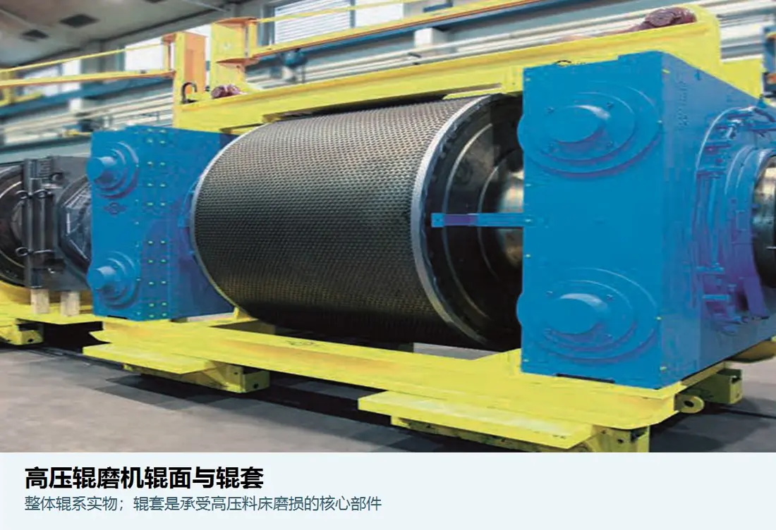
Roll Surface / Roller Tyre
The main working surface of the high-pressure material bed. Check diameter, width, surface design, edges, wear profile and connection to the roll shaft.
View the Component Page →Start with the PM model, roll diameter and width to identify roll wear systems, load-bearing and hydraulic spares, materials and drawing for quotation.
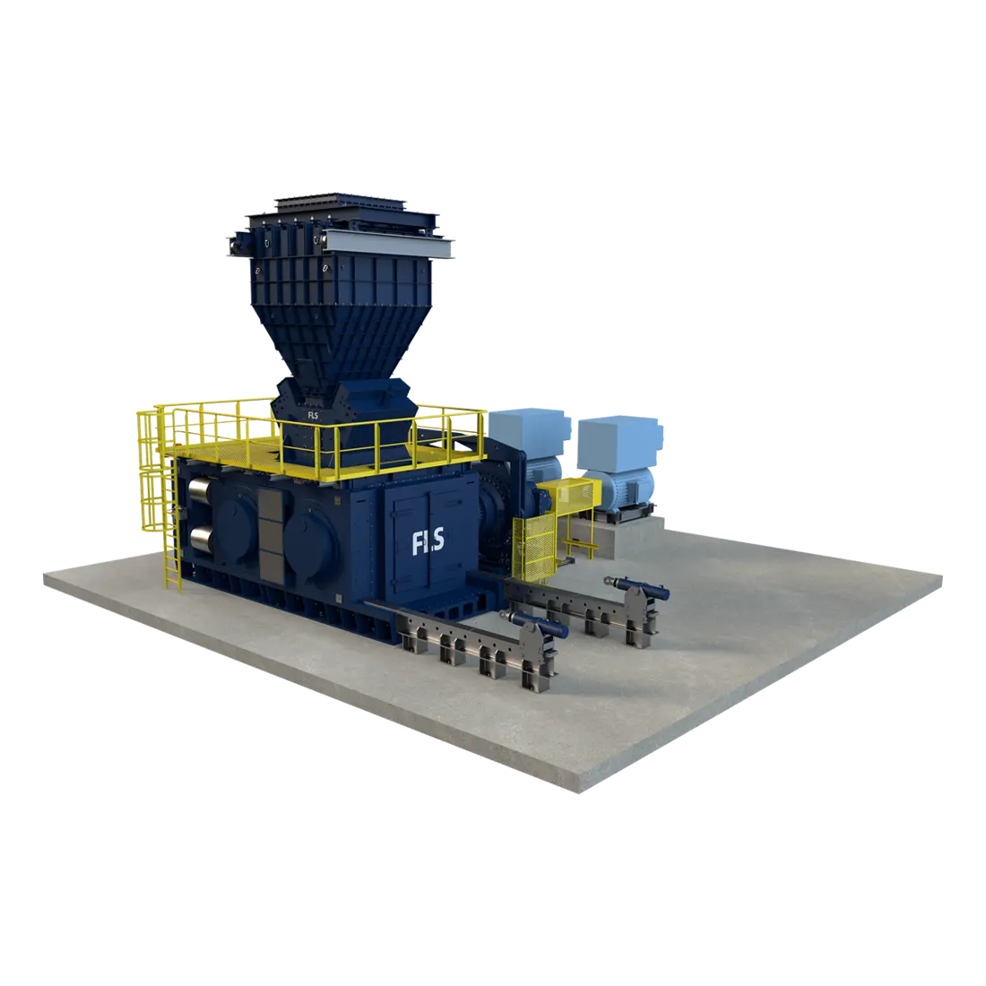
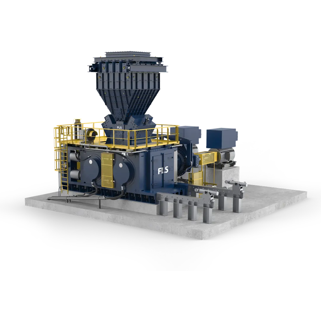
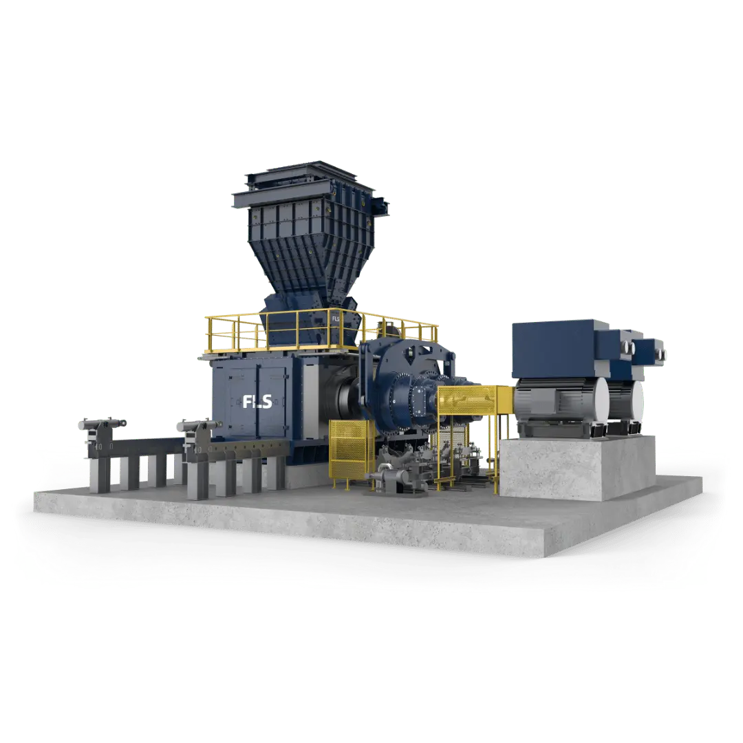
The official FLS HPGR brochure lists roll diameter, width, grinding force, dual-motor power and overall dimensions for PM0, PM1 and PM3 to PM10. HPGR Pro features apply to new machines or confirmed Standard upgrade projects.
Dimensions are from the official FLS HPGR / HPGR Pro Upgrades brochure. For roll surfaces, bearings, hydraulics and drive spares, also verify serial number, fixed/floating roll position and upgrade configuration.
| Model | Size Designation | Roll Diameter × Width (mm) | Grinding Force (kN) | Motor Power (kW) | Length × Width × Height (mm) |
|---|---|---|---|---|---|
| PM0 | 9/7 | 950 × 650 | 2,700 | 2 × 220 | 3,240 × 1,860 × 3,800 |
| PM1 | 11/8 | 1,100 × 800 | 3,400 | 2 × 450 | 3,750 × 2,150 × 4,600 |
| PM3 | 14/8 | 1,400 × 800 | 4,300 | 2 × 500 | 3,735 × 2,164 × 5,400 |
| PM4 | 17/10 | 1,700 × 1,000 | 7,000 | 2 × 800 | 4,490 × 3,030 × 6,800 |
| PM5 | 20/10 | 2,000 × 1,000 | 8,600 | 2 × 1,600 | 5,950 × 3,000 × 7,500 |
| PM6 | 20/15 | 2,000 × 1,500 | 11,000 | 2 × 1,850 | 6,020 × 3,460 × 8,000 |
| PM7 | 20/17 | 2,000 × 1,650 | 13,500 | 2 × 2,500 | 6,550 × 3,640 × 8,800 |
| PM8 | 24/17 | 2,400 × 1,650 | 17,000 | 2 × 2,800 | 7,725 × 3,820 × 9,000 |
| PM9 | 26/18 | 2,600 × 1,750 | 20,000 | 2 × 3,400 | 8,500 × 4,150 × 9,700 |
| PM10 | 30/20 | 3,000 × 2,000 | 25,000 | 2 × 5,000 | 9,500 × 4,600 × 11,000 |
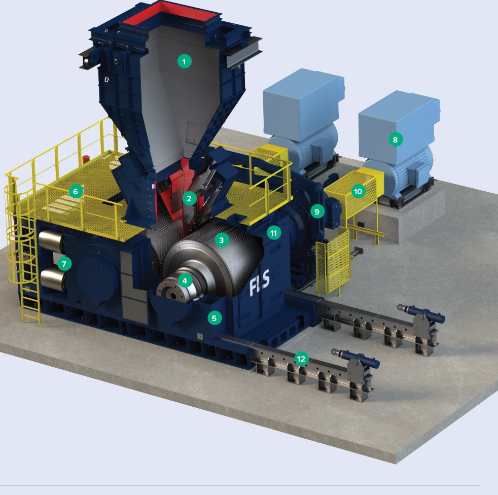
The numbers on the diagram correspond one to one with the rows below.
| No. | Component | Location | Applies to |
|---|---|---|---|
| 1 | Feed chute (lined) | Feed passage above the rolls | HPGR Standard |
| 2 | Feed control gate | Lower feed chute | HPGR Standard |
| 3 | Studded tire | Working surface of grinding rolls | HPGR Standard |
| 4 | Roll shaft | Centreline of grinding rolls | HPGR Standard |
| 5 | Bearing block | Supports at the ends of the roll shafts | HPGR Standard |
| 6 | Maintenance platform | Platform beside the roll assembly | HPGR Standard |
| 7 | Hydraulic cylinders | Hydraulic loading beside the roll assembly | HPGR Standard |
| 8 | Main drive motor | Rear drive end | HPGR Standard |
| 9 | Gear reducers with torque arm assembly | Between the motors and roll shafts | HPGR Standard |
| 10 | Cardan shaft | Drive section between gear reducers and roll shafts | HPGR Standard |
| 11 | Dust enclosure with inspection doors | Enclosure above the grinding rolls | HPGR Standard |
| 12 | Roll extraction frame | Extraction rails below the machine | HPGR Standard |
The roll centre, edges, side plates and feed/discharge passages have different wear mechanisms. The cards link part location and material choices to component pages; final confirmation follows the PM model and drawings.
Roll Surface / Roller Tyre
The main working surface of the high-pressure material bed. Check diameter, width, surface design, edges, wear profile and connection to the roll shaft.
View the Component Page →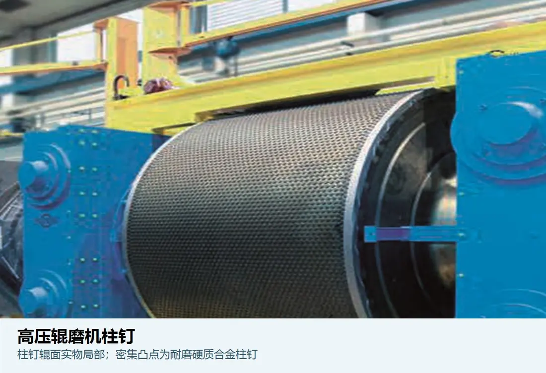
Tungsten Carbide Stud
Embedded studs retain an autogenous protective material bed. Match diameter, length, head shape, spacing density, sockets and edge transitions.
View the Component Page →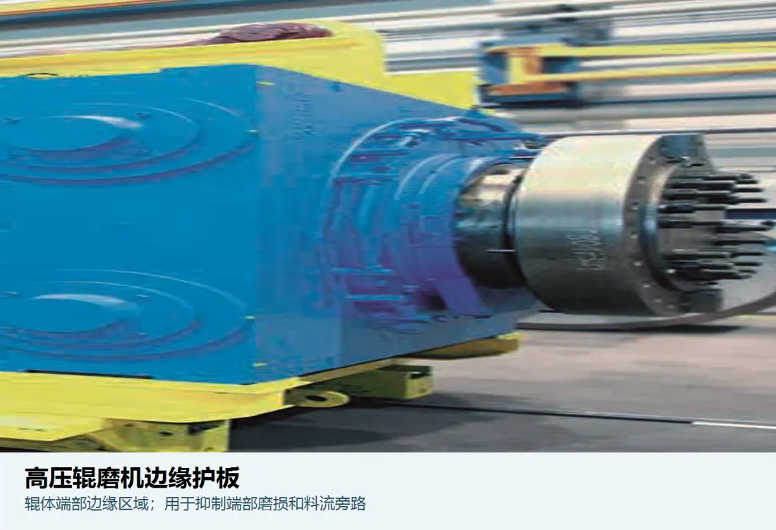
Edge Block / Edge Protection
Protect roll edges and control edge wear. Check inner/outer side, circumferential position, mounting grooves, fastening and transition to the studded area.
View the Component Page →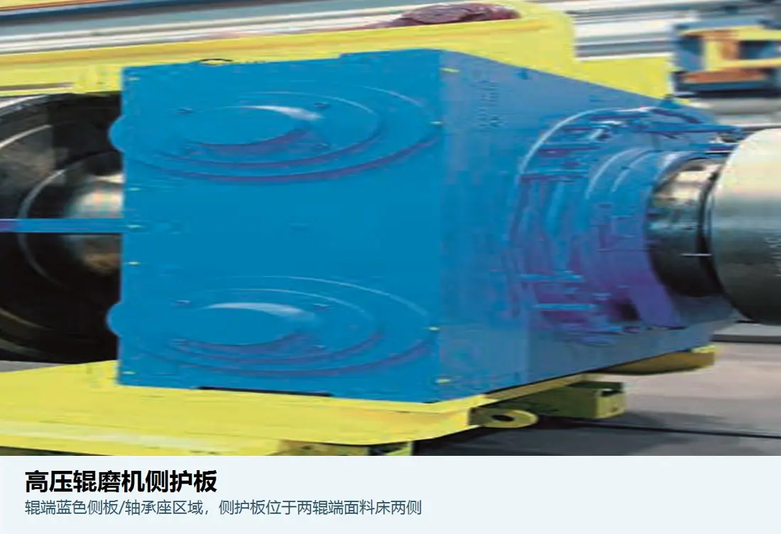
Cheek Plate / Rotating Side-Plate
Contain material at the roll-gap sides under high-pressure abrasion. For HPGR Pro rotating plates, also check the rotating mechanism, clearance and seals.
View the Component Page →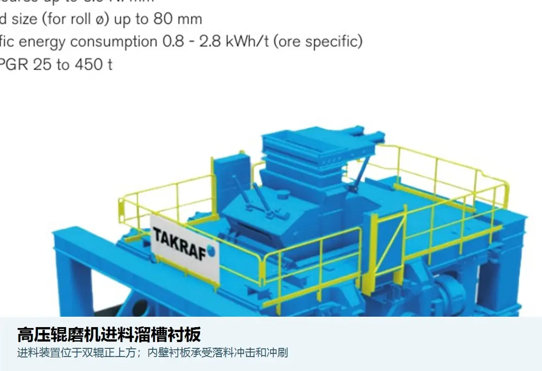
Feed Chute Liner
Withstand coarse-particle impact and stabilize feed to the roll gap. Check position, drop angle, thickness, hole pattern and side-plate interfaces.
View the Component Page →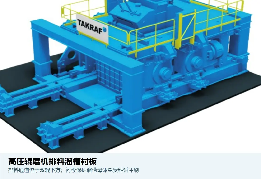
Discharge Chute Liner
Withstand compacted-cake drops, impact and sliding wear. Check drop height, impact point, liner joints, fixing and service access.
View the Component Page →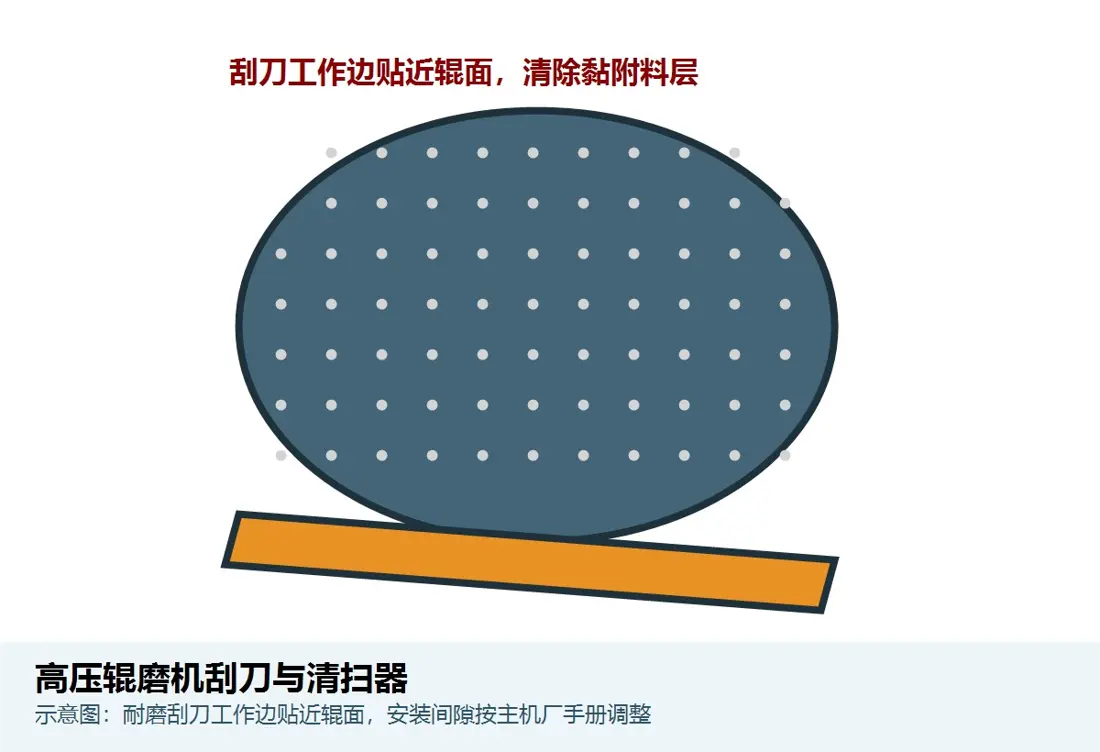
Scraper / Cleaner
Remove adhered material from rolls or passages. Check scraper profile, preload, clearance, movement direction and bracket interfaces.
View the Component Page →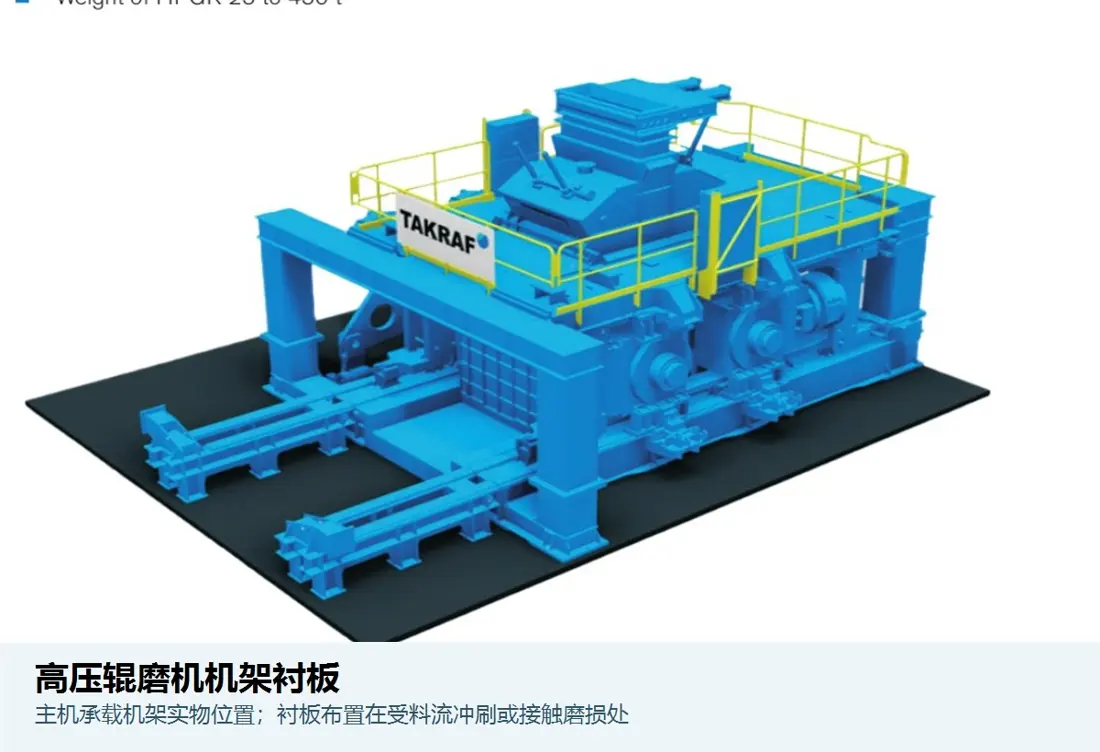
Press Frame / Hopper Liner
Protect frame and hopper areas exposed to impact, compression and sliding wear. Check plate shape, thickness, overlap direction and mounting.
View the Component Page →Distinguish HPGR Standard / Pro, PM model, machine side, fixed/floating roll and upgrade status. Only confirmed reference matches are published on component pages.
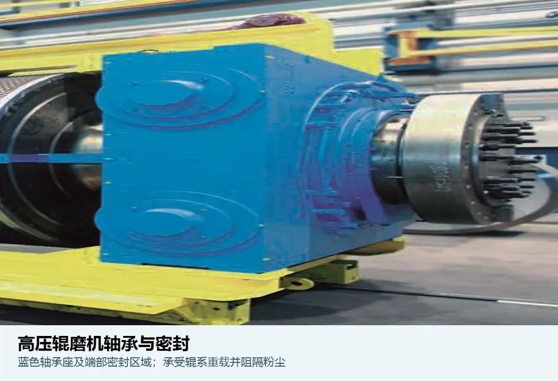
Main Bearing & Bearing Seal
Check PM and bearing models, fixed/floating end, clearance, lubrication, seal design and temperature-monitoring connections.
View the Component Page →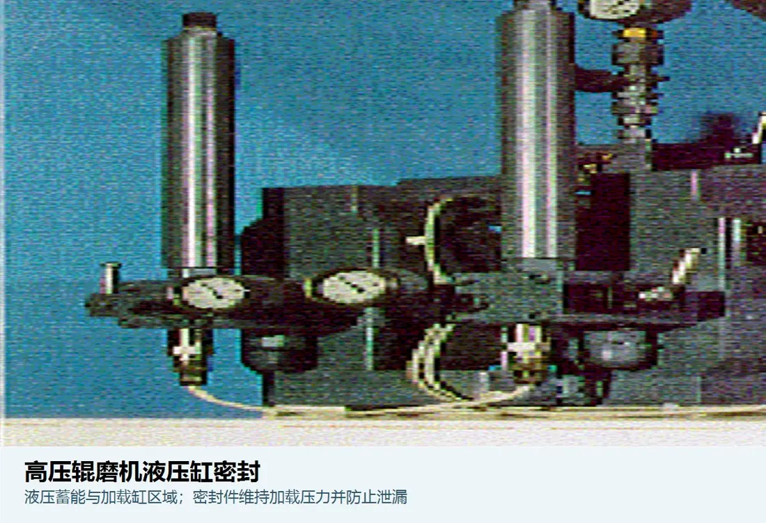
Hydraulic Cylinder & Seal Set
Load the roll gap and move the floating roll. Check bore, rod diameter, stroke, pressure, mounting trunnions, seal grooves and fluid.
View the Component Page →Roll Shaft & Roll Assembly
Include fixed and floating rolls, shafts and connections. Check journals, bearing seats, roll interfaces, concentricity, heat treatment and nondestructive testing.
Send Drawings and References →
Gearbox, Coupling & Drive Shaft
Identify each side of the dual-motor system as an assembly. Check power, ratio, output shaft, coupling, torque limitation and mounting datums.
View the Component Page →Oil Lubrication & Filtration Components
For HPGR Pro oil-lubricated main bearings, check pumps, filters, coolers, valves, pipe connections, oil and monitoring elements.
Send Drawings and References →Mechanical Skew Limiter Assembly
An HPGR Pro assembly that limits floating-roll skew. Check machine size, mounting side, locking design, links and sensor connections.
Send Drawings and References →First check PM model and machine size, then roll diameter, width, serial number, surface type, fixed/floating roll position and Standard / Pro configuration.
FLS states that machine sizes 4–10 can receive Pro upgrades. Each modification and part still requires checks against size, serial number, upgrade scope and modification drawings.
Yes. Submit the reference, PM model, roll diameter and width, location, surface layout, used-part photographs and material data to establish a match.
Provide PM model, Standard / Pro, serial number, fixed/floating roll and side, surface layout, drawings or samples, material and duty. These support identification, material assessment, production at certified foundries, quality control and delivery.
Or contact us directly: +86 156 3797 3199
zzx@anranst.com
ANRANST provides customers worldwide with engineering assessment, production at certified foundries to the customer technical requirements, quality control and finished-part delivery for custom wear parts and industrial spares, with scope to support other custom industrial parts.
We review mating surfaces and interface dimensions and assess material, heat treatment and manufacturing feasibility.
Material grades and heat-treatment processes are specified order by order, stated in the technical agreement and tracked through production.
Drawing confirmation, material and process control, production tracking, inspection and acceptance coordination.
We coordinate manufacturing, quality confirmation, packaging and delivery of complete finished parts in a workable, closed-loop supply process.
Provide the existing model, drawings, drawing, materials or operating conditions so we can identify the appropriate technical review and supply route.
Submit an Enquiry