
HPGR CHEEK PLATE / SIDE LINER
HPGR Side Liners and Cheek Plates
Wear protection and material-bed containment beside the roll gap · Identify by side, profile and clearance
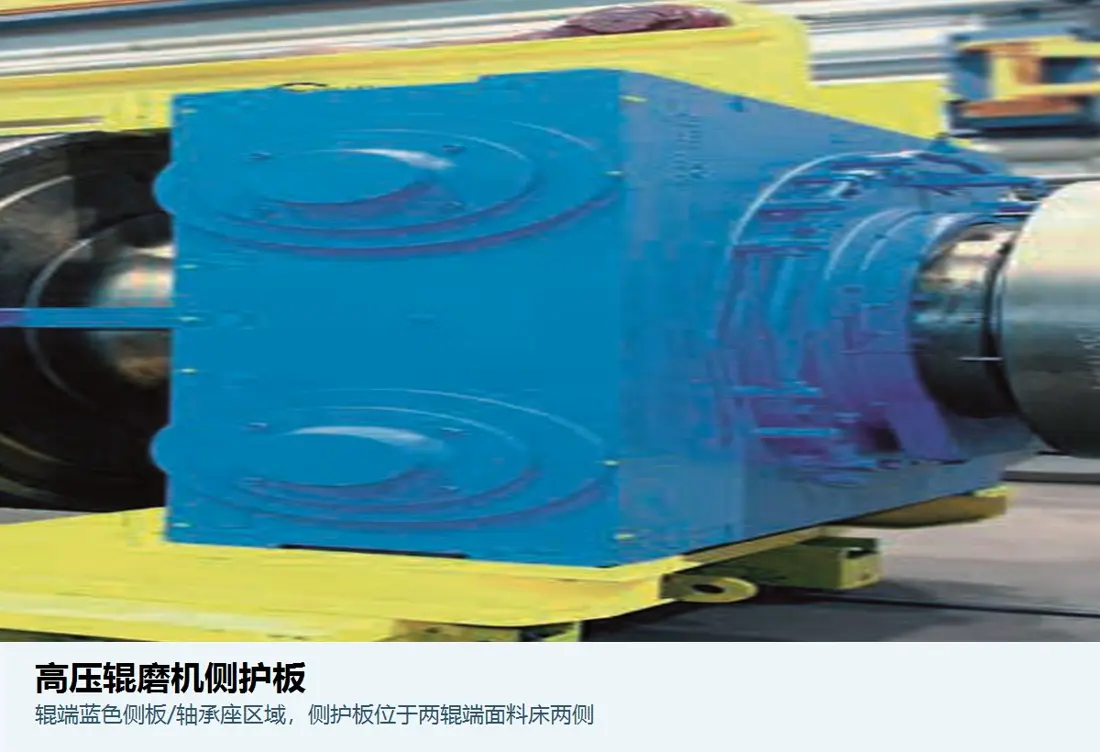
Side liners sit beside the roll gap and material bed, providing lateral containment and protecting adjacent structures. ANRANST checks left/right orientation, fixed or floating roll side, profile, hole pattern, working-surface material, roll-end clearance, failure records and drawing for technical review, quality control and finished-product delivery.
Part Function Orientation identification Left/right, fixed/floating roll side, feed/discharge end Geometry identification Profile, hole pattern, thickness, recessed holes, chamfers and segmentation Clearance identification Working clearance to the roll end, flange or edge structure Material identification Backing plate, working layer, connection method and heat-treatment condition
Contain material beside the roll gap and protect side structures
Side liners and roll ends form the lateral boundaries of the material bed. Working clearance between the plate face, roll end or flange affects leakage, local uneven wear and edge pressure distribution. Similar appearance does not establish interchangeability.
A machine may have left- and right-hand parts, fixed- and floating-roll-side parts, upper and lower parts, or segmented assemblies. Retain position markings during inspection and record adjustment shims, fastening methods and actual clearances.
Position and Performance
Check installation position, clearance and wear layer together
Plate wear changes material-bed boundaries and roll edge conditions as well as reducing part life.
Fixed roll side
Check mounting datums, plate flatness, hole positions and roll-end clearance to prevent one-sided wear caused by assembly errors.
Floating roll side
Account for floating roll travel and clearance at different load positions to avoid interference, trapped material or abnormal leakage.
High-wear feed zone
Subject to material erosion, coarse-particle impact and lateral compression. Confirm the working profile and local material selection using site wear patterns.
Roll-end edge zone
Adjacent to the roll end, flange or edge segment. Excessive clearance can allow leakage; insufficient clearance can cause rubbing and thermal damage.
Segments and connections
Segmented plates, fastening holes, clamping plates, shims and adjustment structures jointly establish location. Retain the assembly sequence during replacement.
Left/right set management
Organise sets by installation side and position number. Record actual thickness, wear and replacement intervals to prevent mixing left- and right-hand parts.
Materials and Manufacturing Processes
Select materials for impact, wear, support and connection conditions
Material families support engineering selection. Confirm grade, hardness, thickness and processing against drawings and technical agreements.
Selection sequence: feed and roll-press duty → lateral erosion and compression → plate wear and clearance loss → material and structural options → dimensional and process inspection → installation records.
Failure Diagnosis
First identify wear, fracture, loosening or loss of clearance control
Similar visible symptoms can result from material, installation, clearance or feed problems.
| Observed condition | Priority checks | Improvement Options |
|---|---|---|
| Rapid plate thinning or grooving | Feed abrasiveness, flow direction, working-zone position, material layer and effective thickness | Optimise material, profile and replacement interval by wear zone |
| Edge chipping or complete plate fracture | Impact, unsupported areas, hole edge distances, fastener preload, material toughness and internal defects | Improve support and connections, and check toughness and manufacturing quality |
| Warping, loosening or hole-area damage | Plate shape, mounting surface, shims, tightening sequence, hole pattern, heat input and operating vibration | Restore mounting datums and control plate shape and fastening procedures |
| One-sided wear or local rubbing | Left/right orientation, fixed/floating roll side, roll-end runout, plate position and working clearance | Recheck installation and clearance over the actual range of movement |
| Increased lateral material leakage | Remaining thickness, roll-end clearance, profile match, uneven feed and adjacent edge structures | Restore material-bed boundaries and inspect adjacent roll surface parts |
Drawings and Inquiry Details
Identify plates by installation position, profile, hole pattern and clearance
Record confirmed drawing and customer model details together. Manufacture to the controlled drawing revision.
Equipment identification
OEM, full model, serial number, roll diameter and width, fixed/floating roll and modifications.
Installation identification
Left/right, fixed/floating roll side, feed/discharge end, upper/lower section and position number.
Geometry and hole pattern
External profile, overall thickness, working layer, hole diameters and spacing, recesses, chamfers, flatness and mounting datums.
Clearances and associated parts
Cold and operating clearances to the roll end or flange, shims, clamping plates, fasteners and adjacent parts.
Drawing or sample and materials
drawing, customer model details, revision, material, hardness and process requirements.
Operating Conditions and Failure Modes
Ore, feed, pressure, throughput, service life, wear measurements, fracture locations and site photographs.
Related Equipment and Parts
Connect side liners with HPGR equipment, OEM installations and materials
This page covers general structures, materials and failures. Use OEM equipment pages to confirm the series, model and installation arrangement.
General High Pressure Grinding Rolls Information Review the relationship between the fixed roll, floating roll, material bed and side structures. HPGR Roll Surfaces and Sleeves Check roll ends, flanged rolls and edge working zones adjacent to the side liners. Metso HRC / HRCe Check HRC / HRCe series, dimensions and side wear-part structures. FLS HPGR Identify side liner installations and drawing through the FLS equipment series. thyssenkrupp Polysius HPGR Check plate positions, orientation and drawing through the brand's equipment series. Quenched and Tempered Wear Plate Review materials, properties and manufacturing requirements for plate-type wear parts.
ANRANST is an independent wear-parts engineering team. OEM names and trademarks belong to their respective owners. Confirm the full model, serial number, drawings, dimensions and actual operating conditions before manufacture.