
HPGR ROLL SURFACE / ROLLER TIRE / FLANGED ROLL
HPGR Roll Surfaces, Tyres and Flanged Rolls
Core Fixed and Floating Roll Assemblies · Identify by Construction, Dimensions and Duty
Covers replaceable roll sleeves or tyres, studded surfaces, hardfaced wear layers and flanged rolls. ANRANST provides equipment identification, material and repair assessment, drawing checks, manufacturing quality control and finished part delivery.
Part Function Structural identification Integral Roll, Separate Sleeve, Tyre or Flanged Roll Wear Layer Studs, Autogenous Wear Bed, Hardfacing or Combined Designs Shaft system interfaces Shaft Diameter, Fit, Key or Locking Assembly, Flange and End Construction Assembly Supply Scope Roll Body, Shaft, Edge Parts, Fasteners and Maintenance Interfaces
Create a High-Pressure Material Bed and Transfer Loads to the Roll Shafts and Bearings
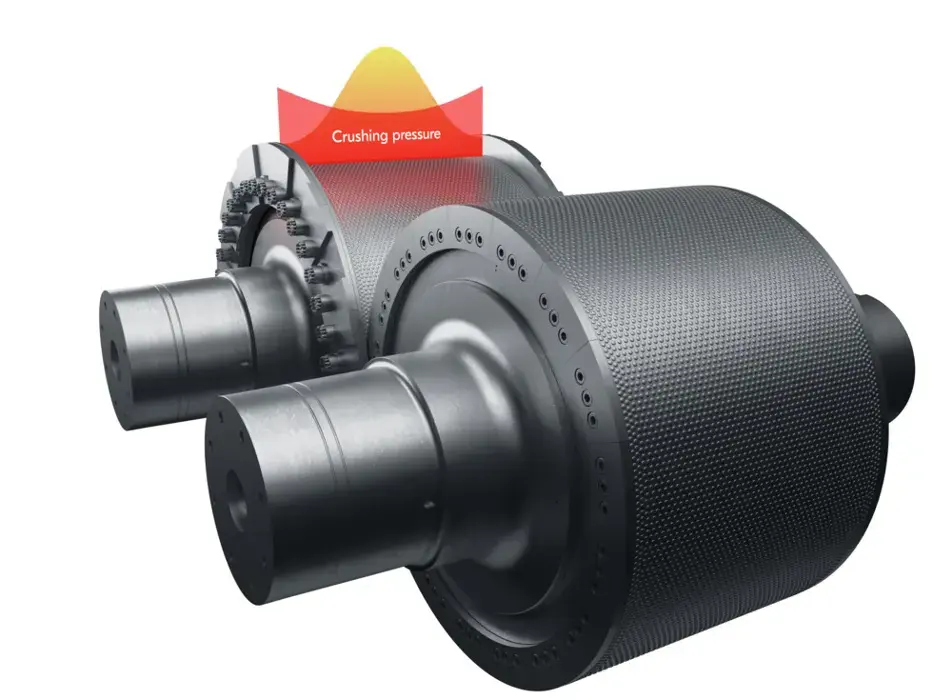
The fixed and floating rolls rotate towards each other, drawing a continuous material bed into the roll gap. The wear layer experiences abrasion, contact fatigue and tramp material impacts. Shafts, bearings and hydraulics work together to maintain the gap, pressure and alignment.
Roll surfaces, sleeves, tyres and flanged rolls cannot be treated as interchangeable by name alone. Equipment generation, diameter, width, shaft connection, flanges, studded or hardfaced systems and edge protection all affect part identity.
Structure and Performance
Roll Surface Designs Address Different Wear and Edge Conditions
Identify the installed construction before selecting materials or repairs. A single roll surface design does not suit every HPGR.
Tyres and Replaceable Roll Sleeves
The wear part is separate from the shaft assembly. Check the bore, fit, shaft shoulder, locking arrangement, removal direction and replacement tools. Metso HRC 8 / HRC 800 use replaceable tyres.
Studded Roll Surfaces
Studs and the supporting body form the wear surface. Check stud diameter, length, tip shape, drawing-specified assembly fit, spacing, hole pattern and stud loss history.
Hardfacing and Surface Repair
Restore the profile through base material assessment, crack treatment, buffer layers and wear layers. Repair feasibility depends on the base material, distortion, remaining dimensions and original manufacturing process.
Flanged Rolls and Edge Segments
Flanges improve pressure distribution across the roll width and control edge effects. Check flanges, bolted edge segments, clearances and skew control as a complete system.
Central High-Load Zone
Continuously exposed to the pressurized material bed and abrasion. Record wear-layer loss, microcracks, loose studs, local spalling and profile changes.
Edges and Transition Zones
Pressure distribution, bypass flow and edge construction can cause uneven wear, chipping and local erosion. Record the left and right ends of fixed and floating rolls separately.
Materials and Manufacturing Processes
Match the Supporting Body, Wear Layer and Carbide Elements
Material families support preliminary engineering selection. Confirm exact grades, properties, heat treatment, hardfacing procedures and acceptance criteria against drawings, analysis of existing parts and the technical agreement.
Selection sequence: equipment and roll surface design → position and loads → existing failure mode → candidate materials and manufacturing process → drawings, inspection and acceptance.
Failure Diagnosis
Distinguish Surface Wear, Structural Damage and Operating Deviations
Operating hours and surface hardness alone do not establish the cause. Compare fixed and floating rolls, left and right ends, pressure, skew and feed records.
| Observed condition | Priority checks | Improvement Options |
|---|---|---|
| Rapid Wear-Layer Loss or Profile Collapse | Ore abrasiveness, pressure, speed, feed distribution, wear-layer construction and thickness | Restore feed and pressure conditions; refine wear-layer design and repair intervals by position |
| Loose, Broken or Extensively Missing Studs | Stud dimensions, tip shape, hole fit, assembly, body cracks, tramp material and local impact | Check stud-to-hole fit and control assembly and base material quality |
| Hardfacing Delamination or Abnormal Crack Growth | Base material, removal of old layers, preheat, buffer layer, interpass temperature, dilution and residual stress | Assess repair feasibility, then establish welding procedures and acceptance criteria for each zone |
| Uneven Wear Between Ends or Rolls | Uneven feed, mechanical skew, flange or cheek plate clearance, hydraulic synchronization and bearing condition | Correct system deviations; increasing hardness at the worn end alone will not resolve the cause |
| Loose or Axially Displaced Tyres and Interface Damage | Bore-to-shaft fit, locking, face contact, torque, shrink-fitting procedure and assembly or removal records | Restore interface dimensions and assembly procedures; recheck the tyre and shaft together |
Drawings and Inquiry Details
Identify Parts by Equipment, Roll Assembly, Wear Layer and Drawing Revision
Provide the drawing, customer model details or project reference, and check it against the installed configuration, interfaces and drawing revision.
Equipment identification
OEM, series, complete model, serial number, commissioning year, fixed or floating roll and modification records.
Key dimensions
Roll diameter and width, shaft diameter, journal, bore, flange, shaft shoulder, key or locking assembly, and assembly weight.
Wear-Layer Construction
Studded, hardfaced, tyre or flanged roll design; stud layout, wear-layer thickness, edge segments and worn profile.
Drawing and Revision
OEM and drawing, customer model details, drawing revision, project number and used part markings.
Materials and inspection
Body, wear layer, stud or edge part materials; heat treatment, hardness, mechanical properties, NDT and dimensional inspection requirements.
Operating conditions and service life
Ore, abrasiveness, maximum feed size, pressure, speed, throughput, current wear life, failure photographs and target life.
Related Equipment and Parts
Parts, OEM Installations, Materials and Enquiries
General parts information explains construction, failure and materials. OEM equipment pages identify series, dimensions and assembly relationships. Drawings and enquiry details support technical confirmation.
General High Pressure Grinding Rolls Information View the machine layout, working positions and related general parts. Metso HRC / HRCe Check HRC 8, HRC 800, HRCe and legacy HRC model dimensions. FLS HPGR Identify installed equipment and drawing through the FLS equipment range. thyssenkrupp Polysius HPGR Identify roll surfaces and shaft assemblies through the OEM equipment range. Carbide Materials Review stud materials, construction and impact limitations. Roll Surface Hardfacing and Repair Review base material assessment, process control and acceptance requirements.
ANRANST is an independent wear-parts engineering team. OEM names and trademarks belong to their respective owners. Confirm the complete model, serial number, drawing, dimensions and actual duty before manufacturing.