FLS Raptor and kubria Cone Crushers

From standard configuration number and core dimensions to mantle, convex slab wear resistance systems. Bronze bushing parts are used for welding of materials with special workpiece equipment; drawing numbers confirmation is available as well ASRFQ

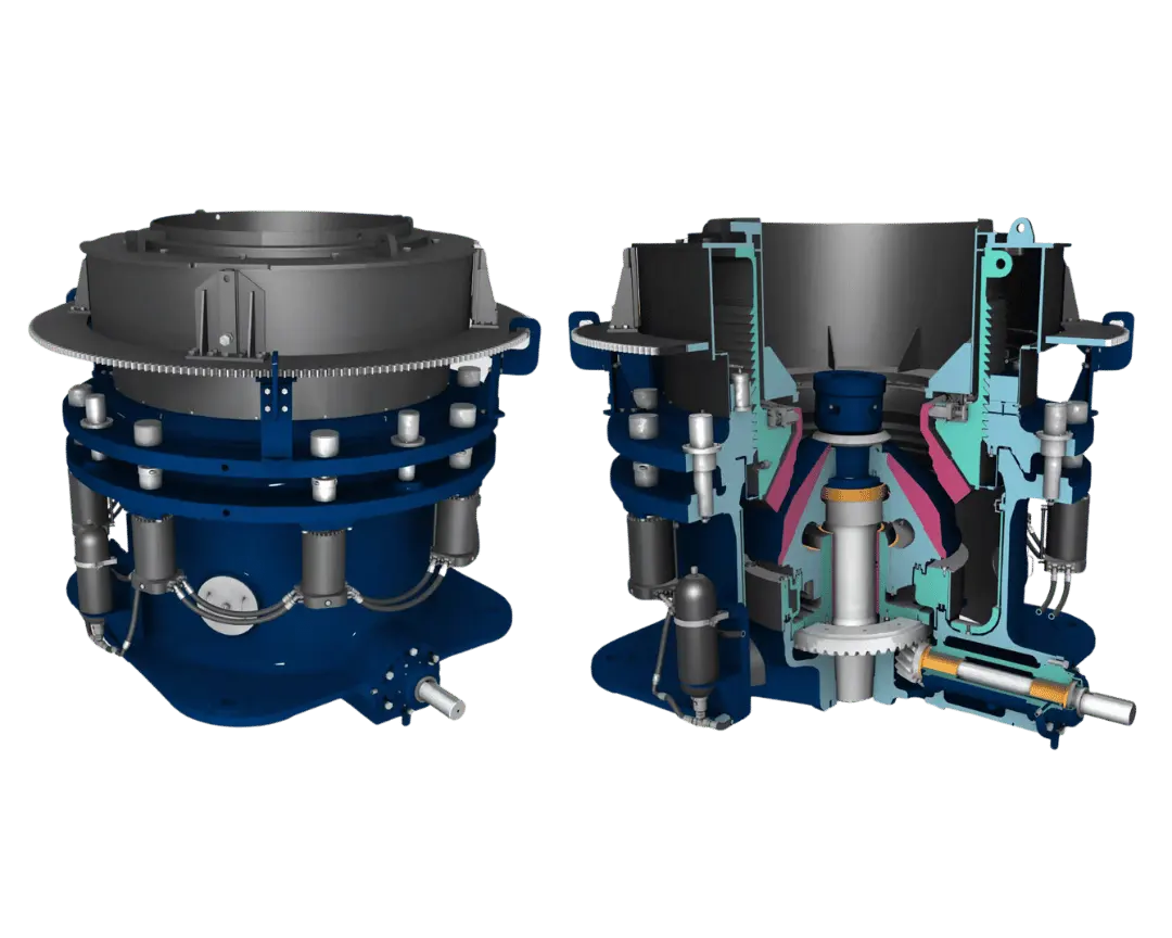
FLS Raptor 500 cone crusher Whole machine and scrawl
FLS Raptor 500 Official full-frame and scrawling can be used Identification smashing cavity, mantle Head, eccentricity and bottom Power Transmission Location.
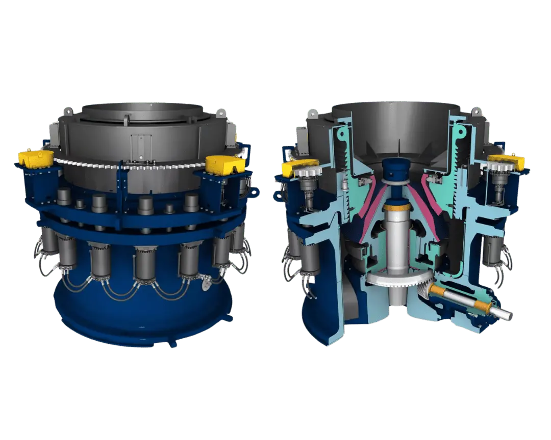
FLS Raptor 2500 cone crusher Whole machine and scrawl
FLS Raptor 2500 Official machine and scrawling diagram, suitable for checking large mines Model the head, bushings Extremes and Power Transmission Construction.
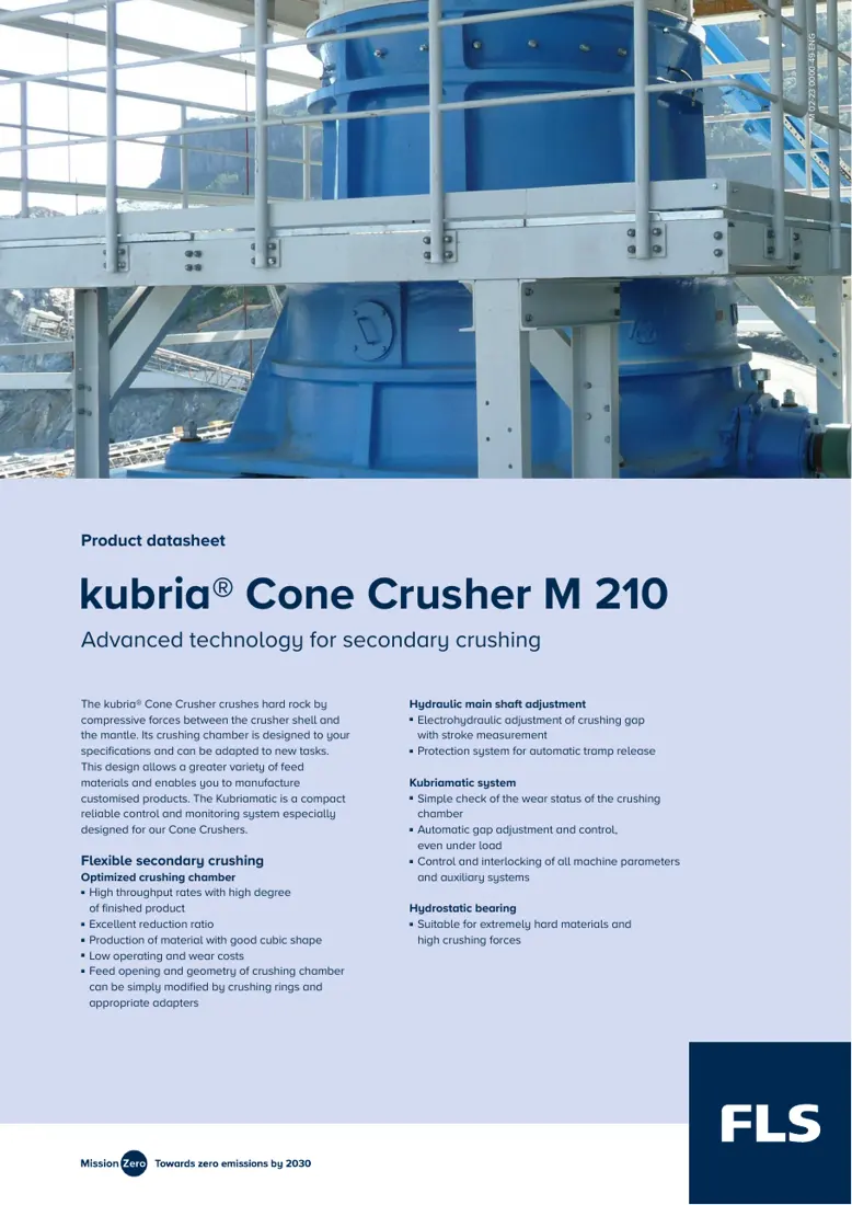
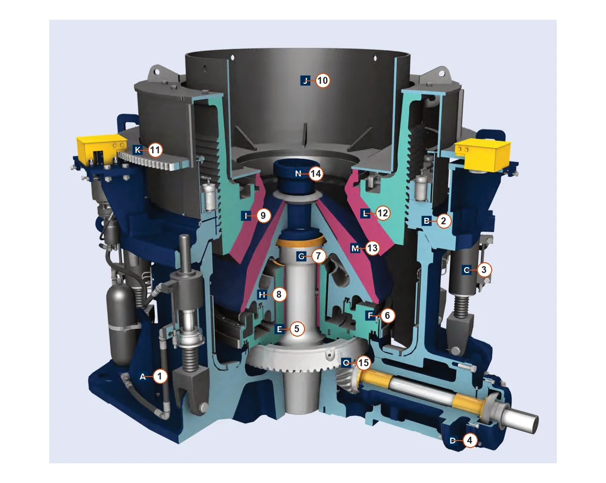
FLS kubria M 210 cone crusher Official data table Home
FLS kubria M 210 Official data table Home. kubria Series Other F 210, F/M 150 and G 150 Core Specifications.
OEM Equipment Details

Two Articles Product Range, model, parts, materials Completed on a page with the workpiece

FLS current Cone crusher line includes Raptor and kubria. This page retains only model, size of the spare parts identification & manufacturing recognition directly required by models such as: installation position; materials or repair equipment information

9 Raptor Specifications line
4 kubria Specifications line
18 wear parts and spare parts Entrance
3 Original Factory Special Tooling
Standard Models and Key Dimensions

Raptor 250 – 2500 model Table

The following maximum feedstock is shown in the highest public value of each cavity profile from official manuals; equipment weight and adjustment ring diameter for installation recognition, not to replace project general arrangement drawing.

ModelMax Feed InletMotor PowerCrusher weightAdapting the maximum diameter of a ring A
Raptor 250235 mm190 kW / 250 hp8,917 kg2,020 mm
Raptor 350240 mm260 kW / 350 hp16,089 kg2,460 mm
Raptor 450335 mm340 kW / 450 hp24,470 kg2,750 mm
Raptor 500330 mm370 kW / 500 hp51,113 kg3,757 mm
Raptor 650380 mm450 kW / 600 hp65,522 kg3,484 mm
Raptor 900345 mm670 kW / 900 hp71,648 kg3,484 mm
Raptor 1100415 mm820 kW / 1,100 hp151,848 kg5,464 mm
Raptor 1300415 mm970 kW / 1,300 hp151,955 kg5,464 mm
Raptor 2500450 mm1,860 kW / 2,500 hp401,089 kg6,785 mm

Ultimately spare parts Still in t complete model, serial number, cavity profile, drawing number, Drawing Revision and matching the size.

kubria Standard Models

F 210, F/M 150, G 150 and M 210 Core Specifications

The diameter of the cone, Feed Inlet Closed by the closed-side setting Maximum feed granularity, maximum power and capacity are derived from the corresponding model the FLS Official data table.

ModelDiameter of the lower coneFeed InletCSS ScopeMaximum feed granularityMaximum capacityDrive power
kubria F 2102,100 mm250 mm10–25 mm200 mm360 tph600 kW
kubria F/M 1501,500 mm300 mm13–45 mm240 mm260 tph315 kW
kubria G 1501,500 mm500 mm30–50 mm400 mm750 tph315 kW
kubria M 2102,100 mm450 mm25–50 mm360 mm1,250 tph600 kW

The maximum capacity to disclose the crushing cavity and material conditions specified in data tables; actual production capacities with materials, cavity profile Extremely high-cost, CSS and feed Condition Changes.

Wear Parts

Crusher chambers, feeders and rack Protection

mantle and concave Put in front of the top, then press feeds and host racking arm with frame arms. Protection Location unfolds. Each entrance connect the unit parts page and Material Page.

mantle liner Identification and installation position References
01

Mantle

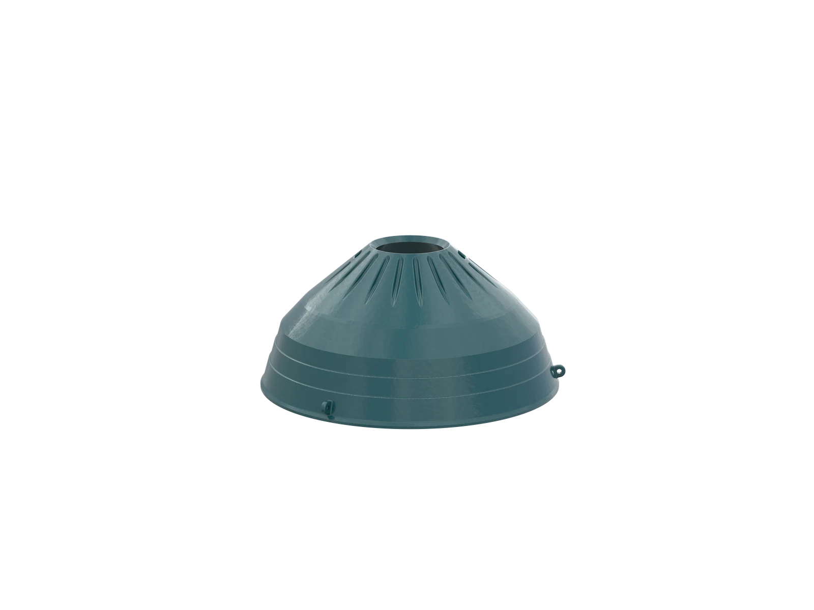
Mantle / Head Liner

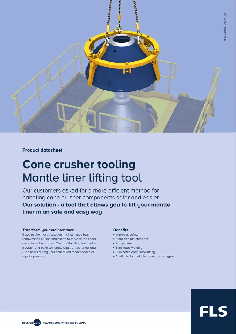
Installed in the head of mantle, together with conve liner forming a crushing cavity. Consolidate an air footprint profile and upper-bottom outlines to height installations; lock structure: closed side closure setting & actual wear profiles

Materials and Manufacturing: high-manganese steel or by operating conditions Verified Specialized Wear-Resistant Alloys Chemical compositions, heat treatment and processing surpluses are confirmed by drawings with ore impact.

View Part Details →
Bowl Liner / Concave Identification and installation position References
02

Bowl Liner / Concave

Bowl Liner / Concave

Fixed on the inner side of a convex or adjustable ring, it is an unfixed wear-resistant surface in crushing chambers. Consolidated cavity profile with upper dimensions and closedside setting; bearing surfaces for pour back strap gap & shaft partition

Materials and Manufacturing: high-manganese steel or Specialized Wear-Resistant Alloys By Material Hardness granularity, impact and abrasive wear and Target Service Life Confirmation.

View Part Details →
Package inlet/ feed cone Identification and installation position References
03

Package inlet/ feed cone

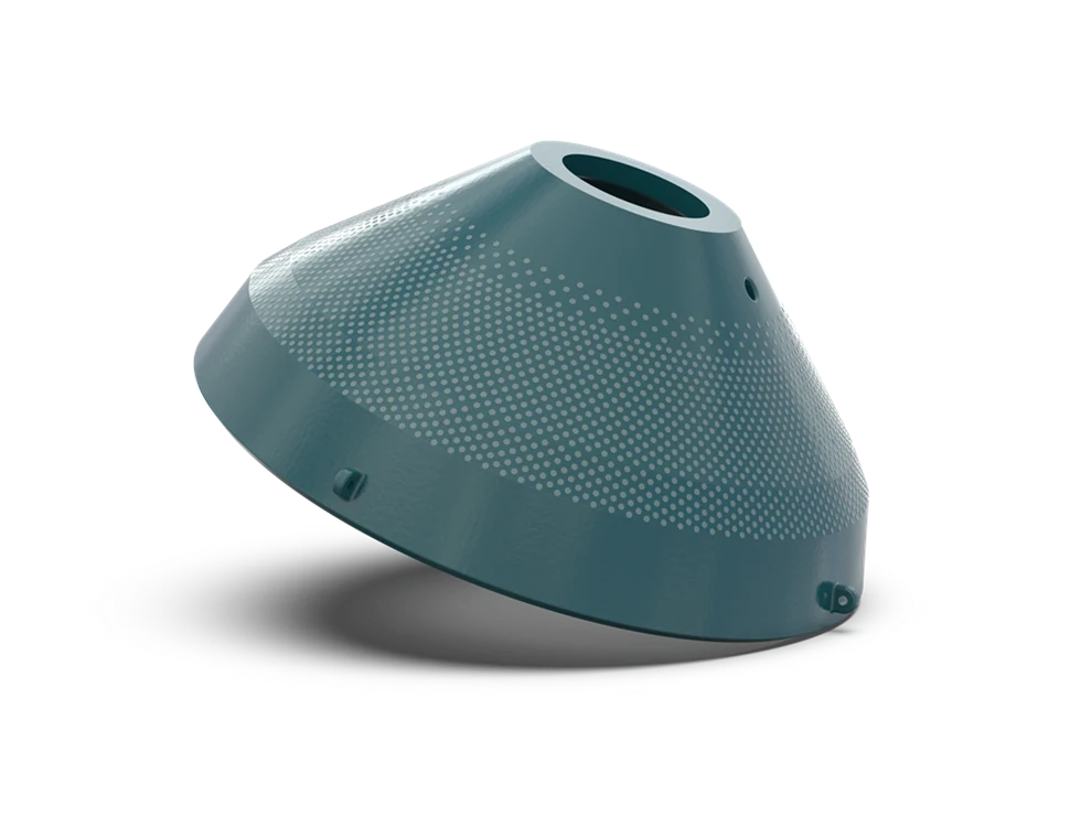
Feed Plate / Feed Cone

Located at the top of Mantle or ingestion center, it withstands a fallout impact and directes materials into crushing chamber. Nuclear outer diameter / centre hole; cone surface: sealed holes - rotational direction & peripheral interference

Materials and Manufacturing: high-manganese steel, Wear-Resistant Alloy Steel or Composite wear-resistant construction By impact and sliding wear Proportional recognition.

View Part Details →
main-frame liner Identification and installation position References
04

Main Frame Liner

Mainframe Liner

Protects the main frame The surface of the internal exhaust, rebound and scrap. Converging machine side differences; arcades - block numbering: plate thicknesses (plate), hole lines or drain channels).

Materials and Manufacturing: Quenched and Tempered Wear Plate, bimetal composite board or Wear-Resistant Cast Steel Confirm by plate thickness, impact and fixed manner.

View Part Details →
frame-arm guard Identification and installation position References
05

Main Frame Arm Guards

Arm Guard / Arm Liner

Protection of the arm and adjacent discharge zone. Contrast arms, left-hand positioning pads with a hole system for coupling relationships Power Transmission Interfering space on the side.

Materials and Manufacturing: Quenched and Tempered Wear Plate, high-manganese steel or bimetal composite Construction Dropping the impact and abrasive wear Confirmation.

View Part Details →
counterweight guard Identification and installation position References
06

Counterweight Guard

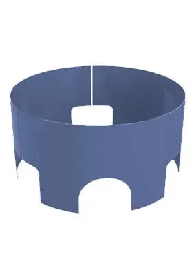
Counterweight Guard / Liner

The original factory slicing diagram is used to identify the weight and its protective area, not as a single part physical map. Contrast models with orientation for installation in shape enveloped by configuration of structure requirements fixed mode or dynamic balance requirement

Materials and Manufacturing: wear-resistant steel plate or confirmed by the original drawings alloy steel Protection (a) parts; materials Changes must be reconciled simultaneously Mass and Balance.

View Part Details →
Spare Parts

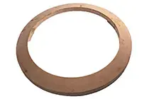
bronze bushing, gear, bearing Hydraulics, tightness and sealing

Same name parts Raptor and kubria Specifications and Different cavity profile can not be interchangeable only by appearance; Required Checks drawing number, and the co-operations; materials and heat treatment.

Socket Liners / Bowl Form bearing Identification and installation position References
01

Socket Liners / Bowl Form bearing

Socket Liner

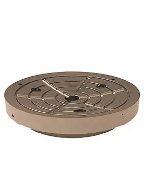
Package mantle The head and the spherical sliding bearing is formed. Contrast a surface radius, internal or external diameters groove oil tank to stop gate wall thickness Contact stained spots and lube conditions.

Materials and Manufacturing: Copper Alloys for Bearings Labels and casting Quality, machining precision and oil tank by face pressures to raise temperature as well the original drawings confirmed.

View Part Details →
Upper head bushings Identification and installation position References
02

Upper head bushings

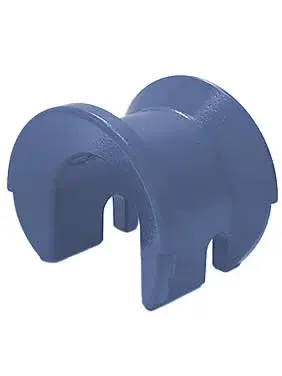
Upper Head Bushing

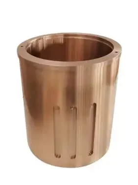
Original factory slicing diagram used Identification mantle The upper side of the head is girded. Converging axle diameter, bushings Internal and external diameters, length of the oil groove or upstream Mounting Directions.

Materials and Manufacturing: Copper Alloys for Bearings Accurate overload, sliding speed and lubrication as well.

View Part Details →
Lower head bushings Identification and installation position References
03

Lower head bushings

Lower Head Bushing

Original factory slicing diagram used Identification mantle The head is girded in the lower side of a position. It's with top bushings Converging separately, it must not be interchanged only by appearance.

Materials and Manufacturing: Copper Alloys for Bearings Confirm by axis and neck, oil filming or temperature rises.

View Part Details →
eccentric bushing Identification and installation position References
04

Eccentric Bushing

Eccentric Bushing

Locations Eccentric assembly Inside, decided Main Shaft The polemic relationship is based on the alignment of a polarization distance, rotational direction and internal or external diameters with length; oil sinking.

Materials and Manufacturing: Copper Alloys for Bearings With the steel eccentrics. materials, gaps and lube confirmed according to the original design.

View Part Details →
countershaft bushing Identification and installation position References
05

Drive Shaft Bushing

Countershaft Bushing

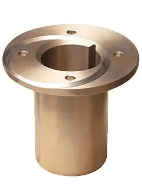
The pivot Power Transmission Axes or Pinion Shaft. Converging the driving side, shaft diameters bushings Length, flange and oil holes; sealing position & axial location.

Materials and Manufacturing: Copper Alloys for Bearings by Speed, proportional pressure and corrosion recognition.

View Part Details →
Gear Wheel Identification and installation position References
06

Gear Wheel

Drive Gear

Original factory slicing diagram used Identification bottom Power Transmission gear Location. Converging the number of mods, teeth numbers and pressure angle; Mounting Distance, hole lineage and side gaps Contact stained.

Materials and Manufacturing: Carbon permeation or morphology Alloy Steels for Drive Parts Touching the teeth Hardness, core toughness and machining precision NDT Confirm by the drawing.

View Part Details →
pinion Identification and installation position References
07

Pinion

Pinion

and Gear Wheel Contraactions. Coupling of moduluses, teeth numbers and vortexes or axles Construction, Mounting Distance and pairing Contact not in a single gear The appearance is directly replaced.

Materials and Manufacturing: Carbon permeation or morphology Alloy Steels for Drive Parts, heat treatment and grinding teeth precision with pairing Gear Wheel Consensual confirmation.

View Part Details →
Thrust Bearing / Thrust Plate Identification and installation position References
08

Thrust Bearing / Thrust Plate

Thrust Bearing

Original factory slicing diagram used Identification The eccentricity and bottom stop-off bearing area. Converging the order of upper, lower combinations Contact Diameter, oil grooves and thicknesses.

Materials and Manufacturing: Copper Alloys for Bearings, Wear-Resistant Alloy Steel Or the original design composite bearing system is confirmed by surface pressure and lubrication.

View Part Details →
Clamping Cylinder Assemblies Identification and installation position References
09

Clamping Cylinder Assemblies

Clamping Cylinder Assembly

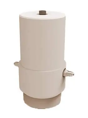
Used to adjust ring clamping or related hydraulic maintenance Function. Contrast the diameter, strokes and pressure Mounting Ear shafts, ductstickes and sealing Refining Grooves.

Materials and Manufacturing: hydraulic cylinder alloy steel, Surface treatment and NBR, HNBR, FKM or polyurethane The seal is confirmed by pressure, medium and temperature.

View Part Details →
Dust-proof seal Identification and installation position References
10

Dust-proof seal

Dust Shell Seal

Locations mantle Extremes or rack dust protection Construction Nearby. Consolidation seal Type, diameters and Refining Grooves, Contact Faces, sweep conditions and oil products as well.

Materials and Manufacturing: NBR, HNBR, FKM, polyurethane or engineered plastics are confirmed by temperature, dust and lubricating medium.

View Part Details →
Locking Nuts Identification and installation position References
11

Locking Nuts

Locking Nut

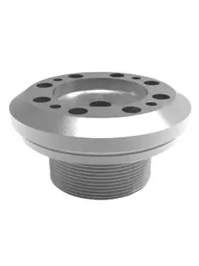
Used for fixed mantle liner Or related head Construction. Vertical screw diameter, thread lengths and rotational direction of the rotor to end surface with wrench Interfaces and with the burning rings or Fastening system Relationships.

Materials and Manufacturing: High-intensity alloy steel Threading Processing and heat treatment Confirm by pre-tension and dismounting method.

View Part Details →
Burning Rings / Firering Identification and installation position References
12

Burning Rings / Firering

Torch Ring / Burning Ring

The original factory layout is used to illustrate the mantle liner demolition relationship in this area, not as a burner physical diagram. Contrast diameters and sections of materials with assembly gaping processes

Materials and Manufacturing: materials With size by specific head Construction and the disassembly solution confirmed, not by universal specifications.

View Part Details →
Specialized Tooling

FLS Official cone crusher Repairs of workpiece

The three parts have FLS official cone crusher dedicated data tables and device-specific images; carrying capacity, hoisting points / interfaces or operating space are confirmed by specific model & site repair solutions.

FLS Official map of head repair platform
01

Head Repair Platform

Head Maintenance Platform

FLS official cone crusher assembly is used to stabilize the headset of a partition, which makes it easy for inspection and replacement wear parts. The platform carrying out loads are confirmed by specific models with interface structures as well in its structure

Submission model With the need for fittings
Drawing and Spare Part Numbers

Raptor 1100 Known third-party public catalogue numbers

The following numbers are from traceable third-party open catalogues, only as information retrieval and RFQ Tracks, not representative FLS Official interchange confirmations.

Applicable ModelsPartCategory: Directory numbersEvidence Properties
Raptor 1100concave liner / ConcaveRXL1010-B003Third-party public catalogues; Mn18Cr2; Manufacturing Previous Post Confirms by Drawing
Raptor 1100concave liner / ConcaveRXL1010-B011Third-party public catalogues; Mn18CrMo; Manufacturing Previous Post Confirms by Drawing
Raptor 1100mantle liner / MantleRXL1010-M004Third-party public catalogues; Mn18Cr2; Manufacturing Previous Post Confirms by Drawing
Raptor 1100mantle liner / MantleRXL1010-M006Third-party public catalogues; Mn18CrMo; Manufacturing Previous Post Confirms by Drawing
Raptor 1100Wedge / WedgeRXL1010-0001Third-party public catalogues; Manufacturing Check the assembly chart before
Raptor 1100Balloon Screw / Spherical NutRXL1010-0003Third-party public catalogues; Manufacturing Check the assembly chart before
Raptor 1100Burning Rings / Torch RingRXL1010-0004Third-party public catalogues; Manufacturing Check the assembly chart before
Raptor 1100Lockboards / Lock PlateRXL1010-0006Third-party public catalogues; Manufacturing Check the assembly chart before
Raptor 1100Tracks of the loop RetainerRXL1010-0007Third-party public catalogues; Manufacturing Check the assembly chart before
Raptor 1100Wedge pads Wedge ShimRXL1010-0008 / 0009Third-party public catalogues; 3 mm / 6 mm; Manufacturing Check the assembly chart before

Selection Guidelines: Complete model, serial number and cavity profile must be matched simultaneously; no explicit drawings can directly make or declare interchanges.

FLS cone crusher What are the main ones currently model ?

Current official information includes Raptor 250, 350, 450, 500, 650, 900, 1100, 1300, 2500, and kubria F 210, F/M 150, G 150, M 210.

parts Just because model Can we direct Manufacturing ?

Cannot. Manufacturing Reconfirmation is required before serial number, cavity profile, drawing number, Drawing Revision, installation position, with the size of materials and old wear record.

Original factory workpieces can be directly named procurement?

Cannot be confirmed only by name. It is also necessary to verify specific Model, Head Construction, Rated Load slinging, Interfaces and the scene Action Space.

Submission FLS cone crusher model, drawing number, cavity profile Or the need for fittings

Providing Raptor or kubria complete model, serial number and OEM/Third Party Numbers; drawings. Photo of used parts & materials with operating conditions we are able to perform part recognition as a result: material assessment - manufacturing matching — quality control — -and finished delivery."

Manufacturing Services in China

From Technical Assessment to Finished-Part Delivery

ANRANST provides customers worldwide with coordinated consulting, supplier sourcing, quality control and finished-part delivery for custom parts, wear parts and industrial spares from China, with scope to support other custom industrial parts.

01

Technical Advice

Equipment and part identification, drawing review, material selection and manufacturing feasibility assessment.

02

Supplier Introductions

Match requirements with suitable manufacturers in China and coordinate the exchange of technical information.

03

Quality Control

Drawing confirmation, material and process control, production tracking, inspection and acceptance coordination.

04

Finished-Part Delivery

Coordinate manufacturing, quality confirmation, packaging and delivery of complete finished parts.

Provide the existing model, drawings, drawing or part numbers, materials or operating conditions so we can identify the appropriate technical review and supply route.

Submit an Enquiry