FLS TSUV, TS, NT and KB Pro Gyratory Crushers

From Standard Models and Key dimensions Entrance Spider and Liners Abrasion system, Main Shaft and Drive spares, materials Converging, Special Tooling, drawing number Confirmation and RFQ.

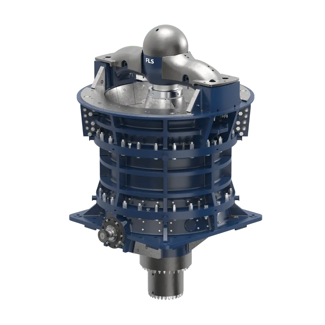
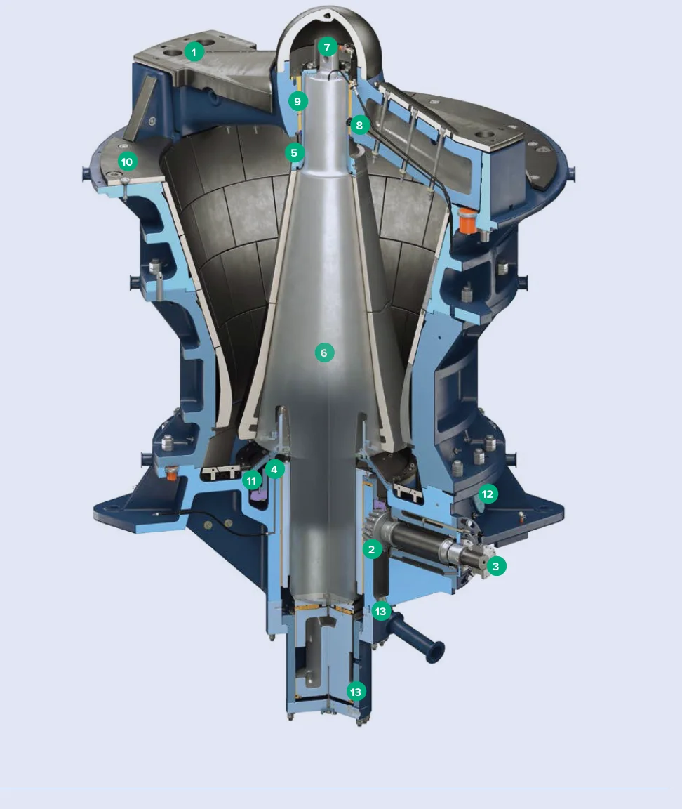
FLS TSUV gyratory crusher Official full-length diagram
FLS Official TSUV Graphics.Specific Equipment From TSUV, TS/TSU, NT or KB Pro Series and complete specifications entered the check-up.
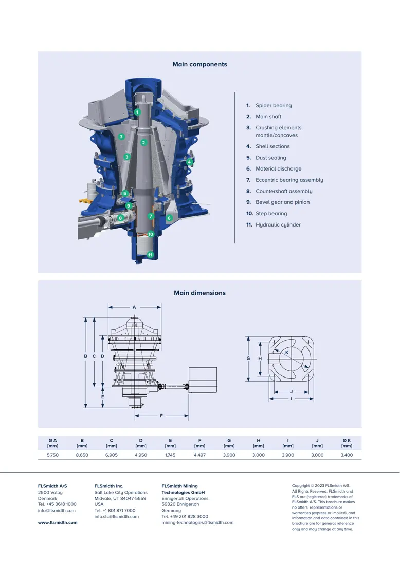
FLS KB 63 - 80 Pro Official Profiles Part / Assembly With size diagrams
FLS KB 63 - 80 Pro Official Part / Assembly Scales and Page: Definition Spider bearing, Main Shaft, Liners Extremely, Power Transmission, and the recession of hydraulic cylinder Location.
OEM Equipment Details

model, Wear Parts, Spares and Tooling Completed on a page

Current FLS The product system is maintained simultaneously TSUV, TS, NT and Gyratory Crusher Pro. Pages are only posted and spare parts Identification Directly related specifications, installation position, materials and the information on fittings.

8 Official Specifications Identification Walk
54–63 in KB Pro Feed Inlet
4,300–14,500 tph KB Pro Publications Capacity
3 Officially available information Special Tooling
Standard Models and Key Dimensions

TSUV, TSU, NT and KB Pro Specifications Table

TSU and NT data are from the FLS current official website comparison table; feed, mantle diameters of KGB Pro'S output lineup is derived by model-based Official Data Table.

Series / ModelEquipment PropertiesFeed Inletmantle Diameterability (tph)Installed Power (kW)
TSUVCurrent Top Service Ultra-Velocity SeriesConfirm by specific specificationsConfirm by specific specificationsSupreme Court 15,000Supreme Court 1,500
TSU 63 × 118Top Service Comparisons of specifications63 in118 in10,0001,200
NT 60 × 113Fuller NT Comparisons of specifications60 in113 in6,0001,000
KB 54-67 ProGyratory Crusher Pro1,370 mm1,700 mm4,300500
KB 54-75 ProGyratory Crusher Pro1,370 mm1,900 mm5,300650
KB 63-80 ProGyratory Crusher Pro1,600 mm2,030 mm6,000750
KB 63-89 ProGyratory Crusher Pro1,600 mm2,260 mm8,5001,000
KB 63-130 ProGyratory Crusher Pro1,600 mm3,300 mm14,5001,500

KB Pro The data table gives the ability to calculate according specified material conditions; actual capacity, power and eccentric distances closed-side setting With ore characteristics and crushing cavity Configuration Changes.

Wear Parts

Spider, concave, mantle and Housing Abrasion system

First, put the beam protections in front of concaveliner and mantle liners as well with mainstay buffering. Each card connect to a single part page or corresponding material pages.

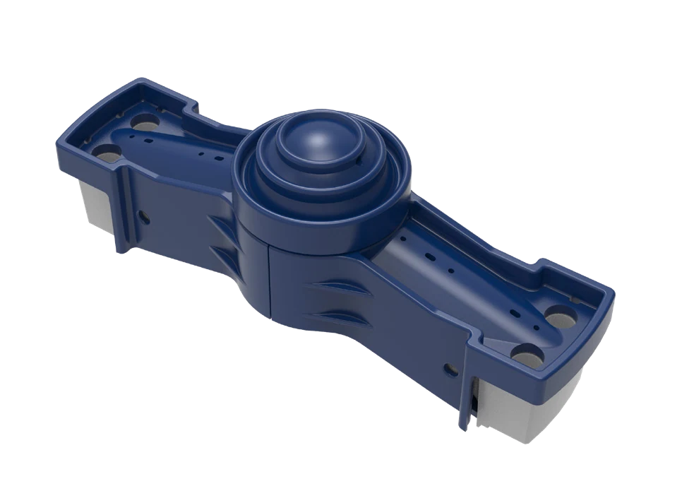
Spider stern, Spider Hats and Arm Guard Identification Figures
01

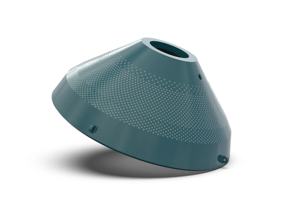
Spider stern, Spider Hats and Arm Guard

Spider Cap, Shield & Arm Liner

Locations Feed Inlet Above, the heavy ore scattering. sliding wear and the scattering of a drop. Spider Construction, number of arms and plate type; hole system: thicknesses.

Material Selection: high-manganese steel, Quenched and Tempered Wear Plate or Composite wear-resistant construction Confirm by impact energy, plate thickness and fixed manner.

View Part Details →
Concave identification image
02

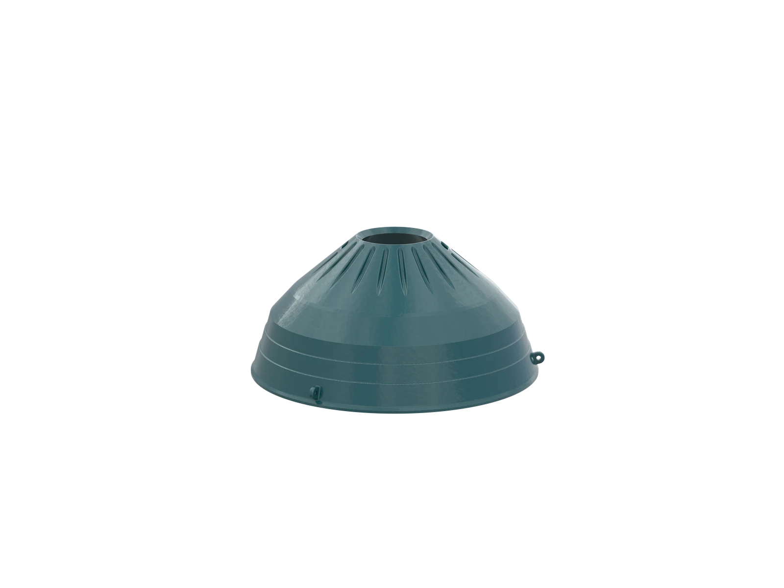
Concave Liner

Concaves

Walks along Housing Sub-paragraph Mounting, and mantle Forming a fractured cavity. Contrast cavity profile, number of layers and method for partitioning the loops in a row with back strap gap as well.

Material Selection: high-manganese steel, Specialty Alloys Or through ore operating conditions Verified composite wear-resistant system, chemical composition and heat treatment Confirm by the drawing.

View Part Details →
Mantle identification image
03

Mantle

Mantle

Package Main Shaft Cone and with Main Shaft sloppy, and concave Together, complete the break. Contrast up and down profile Head nut Interfaces, backpacking and closing side closed-side setting and wearable partitions.

Material Selection: high-manganese steel or Specialized Wear-Resistant Alloys By impact, compression and abrasive wear Combination operating conditions Confirmation.

View Part Details →
Main Shaft Protective Sleeve Identification Figures
04

Main Shaft Protective Sleeve

Mainshaft Sleeve

This is the suitcase. Main Shaft Externally independent protections are not equal Main Shaft Assembly. Contrast the axle diameter, matching lengths and thicknesses of walls with endpoint positionings or disassembly Construction.

Material Selection: Forging or Quenched and tempered alloy steel The surface reinforcement process is confirmed by the original drawings, matching and wear position.

View Part Details →
Pillars under side liners Identification Figures
05

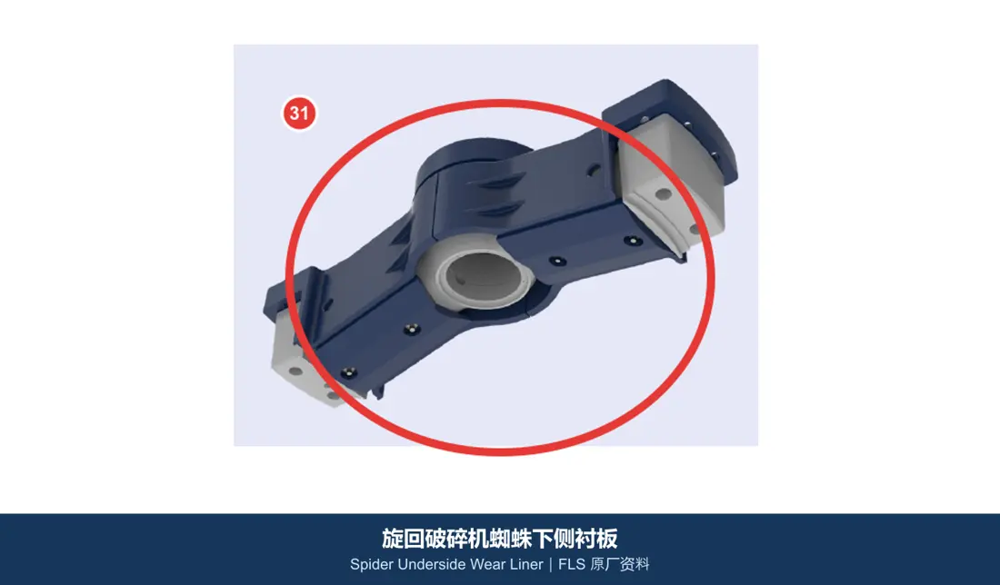
Pillars under side liners

Spider Underside Wear Liner

Protection Spider Or the surface under a pillar is rebounded by ore and sliding wear Area. Converging the right-hand position, plate type and hole lineage; assembly gaps & fitting boarding

Material Selection: high-manganese steel, Quenched and Tempered Wear Plate or bimetal composite Screens for impact and sliding wear Proportional recognition.

View Part Details →
Upper Housing Wear Plate Identification Figures
06

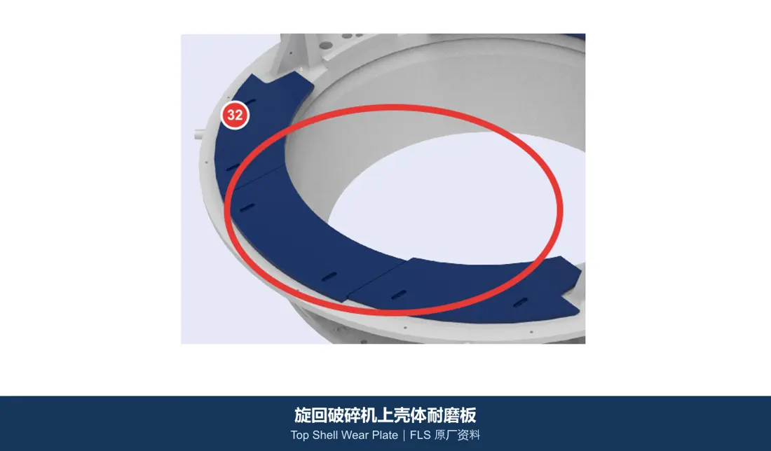
Upper Housing Wear Plate

Top Shell Wear Plate

Protection of protection Housing Intrashell, rebound and local rinsing Construction Surfaces. Converged Housing Layers, plate numbering and align direction. Construction.

Material Selection: Quenched and Tempered Wear Plate, bimetal composite or High-Chromium Abrasion Construction by Mounting Space and impact intensity recognition.

View Part Details →
Hub Liners Identification Figures
07

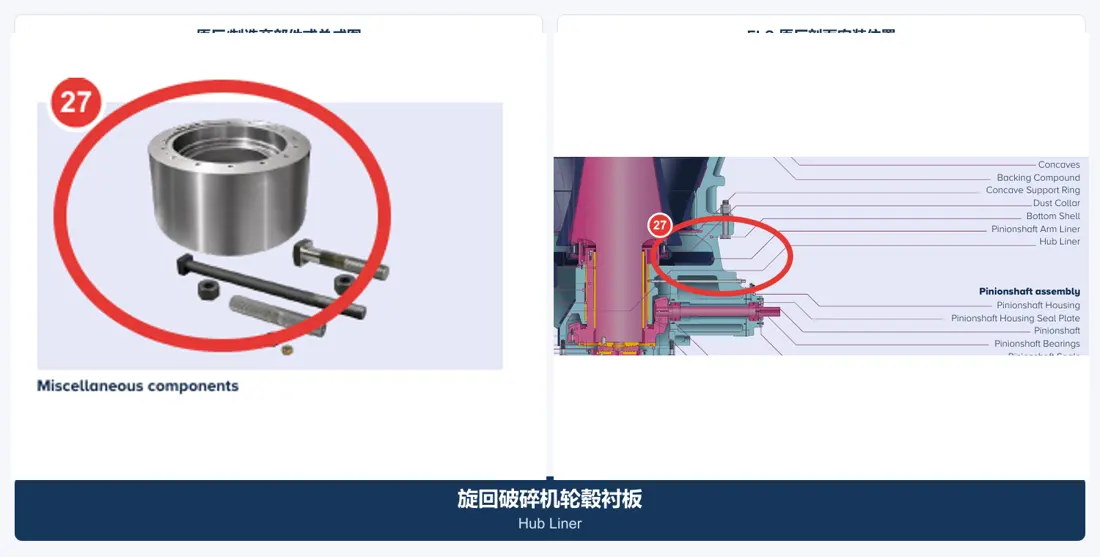
Hub Liners

Hub Liner

Protecting the hubs and their neighbors Construction Avoiding the shading of ore and slab. Mounting Area, arcades and pores systems; stitching gapes.

Material Selection: Quenched and Tempered Wear Plate Or composite wear-resistant plates are confirmed by arc processing, welding and tightening conditions.

View Part Details →
Pinion Shaft Arm Guard Identification Figures
08

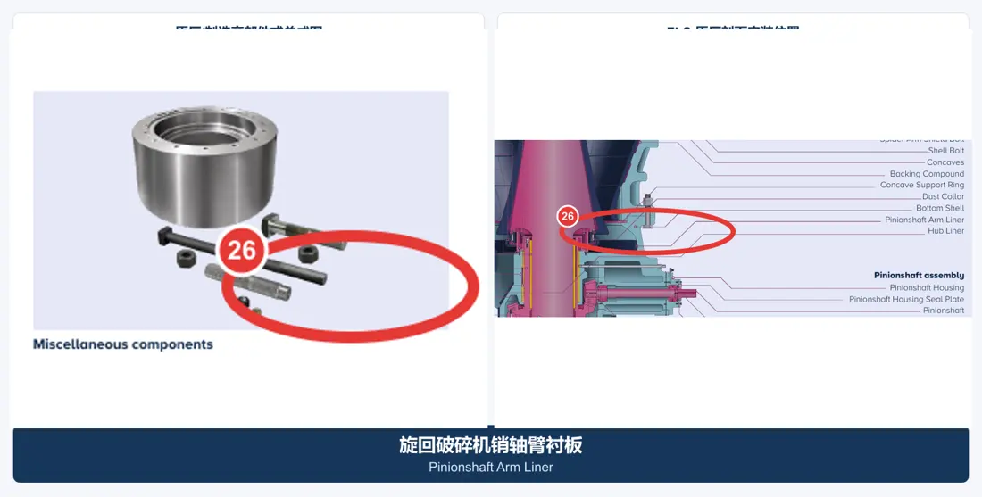
Pinion Shaft Arm Guard

Pinionshaft Arm Liner

Protecting Close Pinion Shaft With the scattering area Housing Or armarm Construction. Converging the machine side, Mounting Direction, interference space and plate thicknesses.

Material Selection: high-manganese steel, Quenched and Tempered Wear Plate or Bimetallic Composites By impact and abrasive wear Confirmation.

View Part Details →
Splash curtain Identification Figures
09

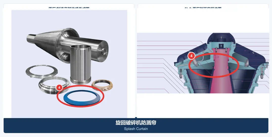
Splash curtain

Splash Curtain

Set in feed or related protective position to control splashes and protect adjacent structures. Contrast the installation location, flexible structure of rigidity / structural dimensions as well for fixing parts

Material Selection: Wear-resistant rubber, polyurethane Or steel wearables Construction Confirm by shock, flexure and temperature conditions.

View Part Details →
Spare Parts

Main Shaft Extremely, gear, bearing Hydraulics and sealing

The main shaft aggregate is separately identified from the keyshade protection boomings; transmission, load and hydraulic spare parts are matched by series of complete models with machine side features as well in drawings.

Main Shaft Assembly Identification Figures
01

Main Shaft Assembly

Mainshaft Assembly

FLS KB Pro Official Part / Assembly Figures in the picture 2 Location Number. Main Shaft Assembly Package Main Shaft and its assembly relationship must be separate Main Shaft Protective Sleeve Differences.

Material Selection: Large Forged Alloy Steel, heat treatment axis and neck precision NDT by model, payloads and original drawings confirmed.

View Part Details →
Eccentric assembly Identification Figures
02

Eccentric assembly

Eccentric Bearing Assembly

FLS KB Pro Official Part / Assembly Figures in the picture 7 No. Location: Contrast eccentric distance, rotational direction and internal-external cooperation; bearing boards with the Lubrication hole path to top or bottom directions

Material Selection: Package of steel and Copper Alloys for Bearings With the use of materials The gaps and oil groove are confirmed by the original drawings.

View Part Details →
Pillars bushings With oil seals Identification Figures
03

Pillars bushings With oil seals

Spider Bushing & Oil Seal

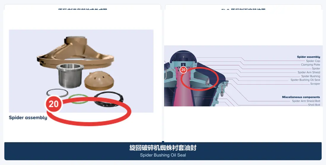
The pivot Main Shaft Upside and keep lubrication. Verify the pillars Construction axis, and bushings Internal and external diameters, flanges / oil sinking or sealed lips as well.

Material Selection: Copper Alloys for Bearings Co-operation NBR, HNBR, FKM Others confirmed by the medium and temperature Seal Materials.

View Part Details →
Pinion Shaft Assembly Identification Figures
04

Pinion Shaft Assembly

Countershaft / Pinionshaft Assembly

FLS KB Pro Official Part / Assembly Figures in the picture.The position of the number is, and axle diameters are paired bearing stern, gear Interfaces, rotary-winging and sealant coverings Construction (8)

Material Selection: Forged Alloy Steels for Drive Parts, bearing Steel and Seal Materials By load, Speed, heat treatment and accuracy grade confirmation.

View Part Details →
Gear Wheel and pinion Identification Figures
05

Gear Wheel and pinion

Bevel Gear & Pinion

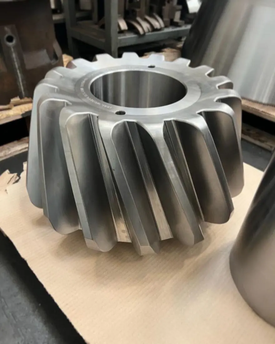
FLS KB Pro Official Part / Assembly Figures in the picture 9 Node position. Must be paired with the number of mods, teeth numbers and pressure angle or spiral direction Mounting Distance, side gap and Contact stained.

Material Selection: Carbon permeation or morphology Alloy Steels for Drive Parts Touching the teeth Hardness, core toughness and grinding & pairing Inspection Confirmed according to the original design.

View Part Details →
Main Shaft Step Plate Conclusions Identification Figures
06

Main Shaft Step Plate Conclusions

Step Bearing Components

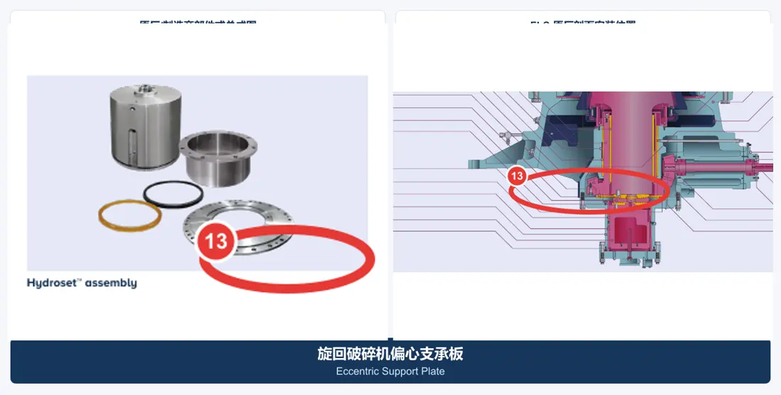
FLS KB Pro Official Part / Assembly Figures in the picture.The number of positions, the check-in order Contact Diameter, oil film gaps and tug surfaces as well hydraulic adjustment Construction (10)

Material Selection: Wear-Resistant Alloy Steel and Copper Alloys for Bearings Confirm by surface pressure, lubrication and flatness requirements.

View Part Details →
hydraulic cylinder Combined with adjustment Identification Figures
07

hydraulic cylinder Combined with adjustment

Hydraulic Cylinder & Adjustment Assembly

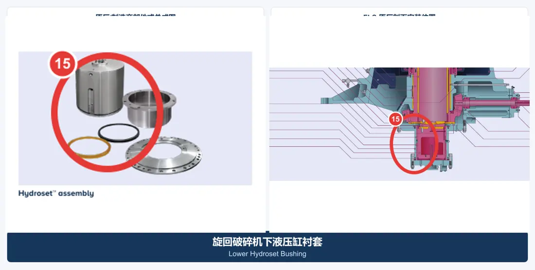
FLS KB Pro Official Part / Assembly Figures in the picture 11 Node position. Converging the cylinder diameter, strokes and pressurers bushings, sealing Refining Grooves Tubes, Traffic Interfaces and control systems.

Material Selection: hydraulic cylinder alloy steel, copper alloys and polyurethane / NBR/HNBR/FKM The seal is confirmed by pressure and medium.

View Part Details →
Dust Seal System Identification Figures
08

Dust Seal System

Dust Sealing System

FLS KB Pro Official Part / Assembly Figures in the picture. Contrast the sealing ring, differential pressure or blow-out conditions; Refining Grooves Sizes, Contact Faces and accessories Dust collar (5)

Material Selection: NBR, HNBR, FKM, polyurethane or engineered plastics are confirmed by temperature, dust and oil products as well.

View Part Details →
Specialized Tooling

FLS Official gyratory crusher Repairs of workpiece

The following three categories have FLS official data tables and device-specific images.The page shows its use, the specific carrying capacity of pods must match with installation models as well for onsite repair schemes

FLS Main Shaft Official map of transport and repair scaffold
01

Main Shaft Transport and repair scaffold

Mainshaft Transport Stand

FLS official assembly is used for bearing, suspension connection and transport gyratory crusher spindles as well to protect key shaft neck. The specific pinpoint of the load capacity or interface are confirmed by a mainshade model

Submission model With the need for fittings
FLS Head nut Safety and Security Tool Upgrades of official data
02

Head nut Safety and Security Tool Upgrades

Headnut & Safety Tool Upgrade

FLS official equipment is used for the tightening and disassembly of head screws, reducing direct participation in assembly processes. Applicable model / counterforce structure & operating space are confirmed by installment

Submission model With the need for fittings
FLS Spider Assembly Official graphic of the hookup
03

Spider Assembly Hooking hoofs

Spider Lifting Hook

FLS official reverse hoisting hooks are built from the bottom of a beam assembly for cross-bow disassembly and transshipment. The lift, openings to open doors will be fitted with an assigned load as well in maintenance bracket that is matched by equipment

Submission model With the need for fittings
Drawing and Spare Part Numbers

Known OEM or third-party number corresponds to model and installation position

The full series is provided with the model, serial number and part name as well for installation position. General arrangement drawing or assembly drawings are available at a time of submission; photographs from used parts have been created in traceable matching relationships accordingly

FLS gyratory crusher How to confirm specific model ?

First distinguish TSUV, TS/TSU, NT or KB Pro Series Re-checking the full specifications, serial number, Feed Inlet, mantle Diameter, general arrangement drawing and Drawing Revision.

Main Shaft and Main Shaft Protective Sleeve Is it the same? parts ?

No. Main Shaft loaded Core Parts, Main Shaft Protective Sleeve y Mounting Main Shaft Externally independent protections, both check-in drawing number Scales and materials.

Third Party drawing number Can the need for fittings be reconciled together?

Can be submitted third-party numbers, complete model, Equipment general arrangement drawing, installation position After the old data can be reconciled simultaneously parts Relatively related and repaired equipment Interfaces.

Submit the FLS gyratory crusher model, drawing number, liner arrangement or tooling requirements

Provide a series with complete model, serial number / OEMs and third party numbers; drawings of used parts (material) photos & operating conditions. We then finish part identification process to evaluate materials for manufacturing matching quality control as well AS finished-part delivery

Manufacturing Services in China

From Technical Assessment to Finished-Part Delivery

ANRANST provides customers worldwide with coordinated consulting, supplier sourcing, quality control and finished-part delivery for custom parts, wear parts and industrial spares from China, with scope to support other custom industrial parts.

01

Technical Advice

Equipment and part identification, drawing review, material selection and manufacturing feasibility assessment.

02

Supplier Introductions

Match requirements with suitable manufacturers in China and coordinate the exchange of technical information.

03

Quality Control

Drawing confirmation, material and process control, production tracking, inspection and acceptance coordination.

04

Finished-Part Delivery

Coordinate manufacturing, quality confirmation, packaging and delivery of complete finished parts.

Provide the existing model, drawings, drawing or part numbers, materials or operating conditions so we can identify the appropriate technical review and supply route.

Submit an Enquiry