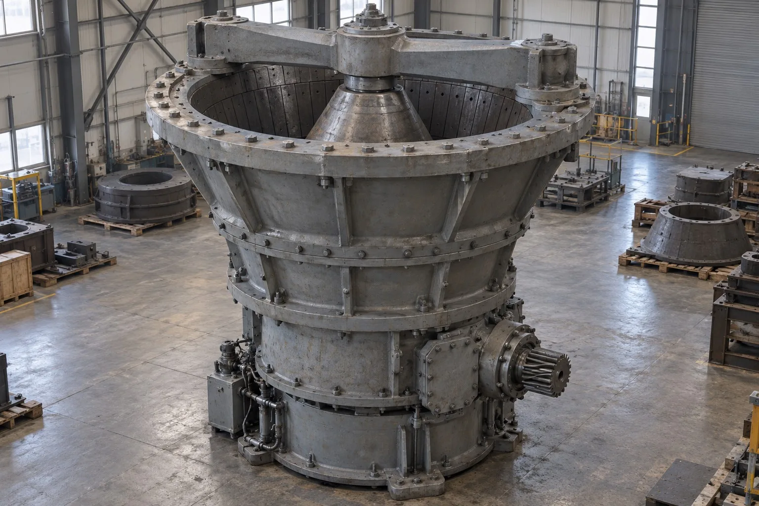
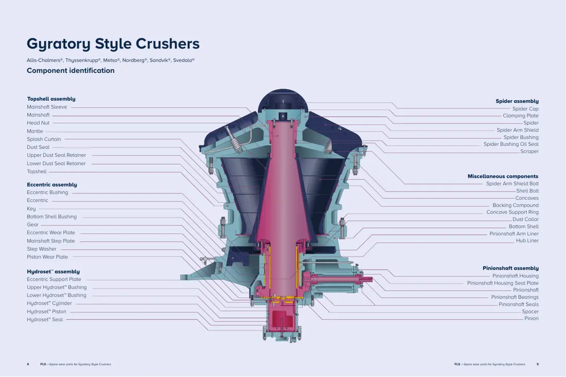
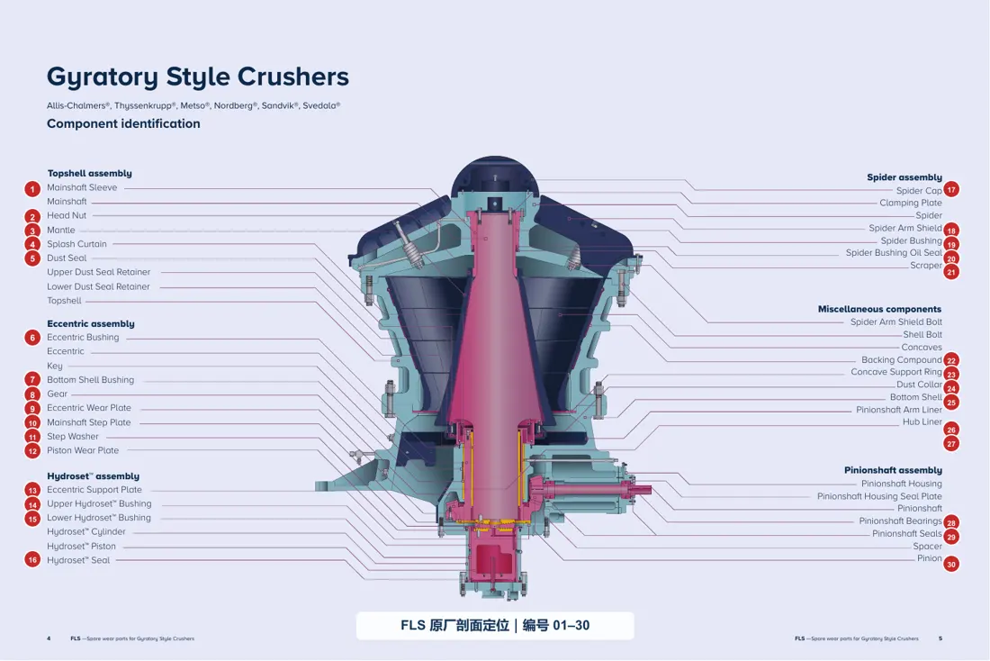
Gyratory crushers are commonly used for primary crushing in large and very large open-pit and underground mines. The eccentric assembly gyrates the mainshaft and crushing head, creating a continuously changing crushing chamber between the mantle and the segmented concaves fixed inside the top shell. Wear and replacement parts include the mantle and concaves as well as spider protection, copper-alloy sliding pairs, the hydraulic mainshaft-position system, gear pair, bearings, seals and shell protection liners.
5 core assemblies · 36 individual parts
Part Identification and Technical Details
Each image combines the part name, material, installation position and maintenance classification. Select a part to open its general spare-part page.
Core assemblies
Major Components and Assemblies
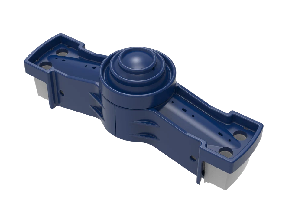
Core AssembliesSpider Assembly
The spider body, spider cap, spider-arm guards, spider bushing and seals form one assembly that must be checked against the machine model and assembly drawing.
Core AssembliesMainshaft Assembly
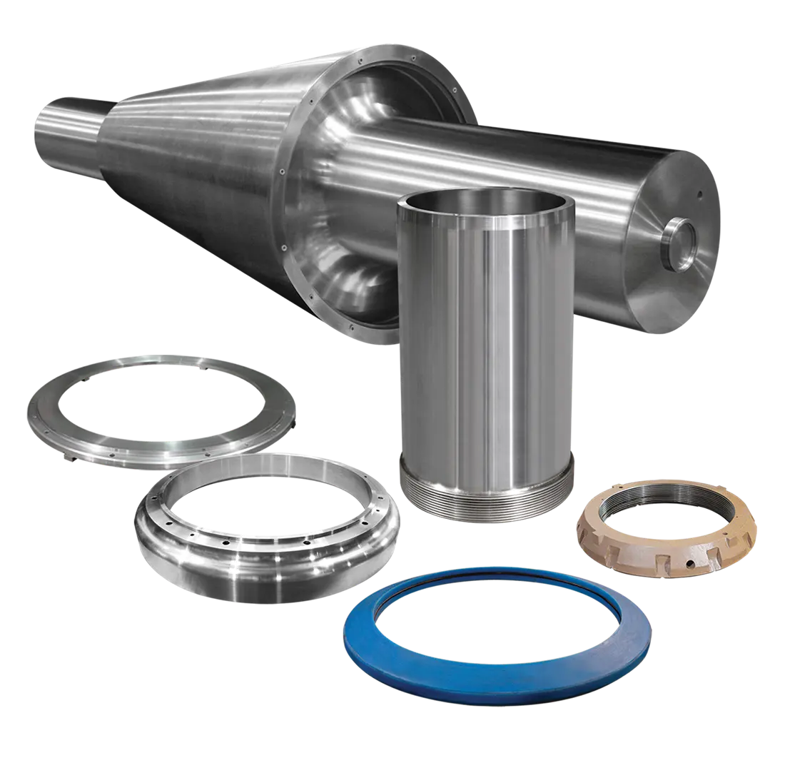
The mainshaft, mainshaft sleeve, head nut, mantle and associated fitted parts are identified by their assembly relationship.
Core AssembliesEccentric Assembly
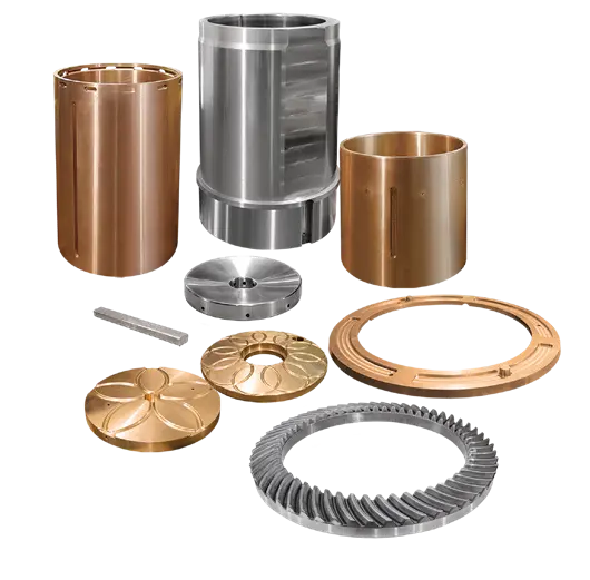
The eccentric, eccentric bushing, ring gear and axial wear parts form the gyrating drive system.
Core AssembliesHydroset Assembly
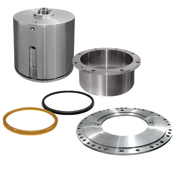
The hydraulic cylinder, piston, upper and lower bushes, seals and thrust components control the mainshaft's axial position.
Core AssembliesPinionshaft Assembly
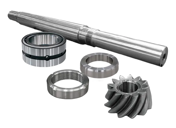
The pinion shaft, bearings, seals, housing and pinion are identified as a matched drive assembly.
Individual parts
Individual and Maintenance Parts
01
Spider
- Installation Position
- Spans the feed opening at the top of the machine and supports the upper end of the mainshaft.
- Main Function
- Resists feed impact while guiding and supporting the upper end of the mainshaft.
03
Mantle
- Material Options
- Austenitic manganese cast steels such as Mn18Cr2 and Mn22Cr2; validated composite-reinforced options where applicable
- Installation and Function
- Moving crushing surface on the outside of the crushing head
- Maintenance Category
- Key Wear Parts
06
Eccentric Bushing
- Material Options
- Bearing bronzes such as C93200 and C93800, or OEM-specified centrifugally cast copper alloy
- Installation and Function
- High-bearing-pressure sliding pair within the eccentric assembly
- Maintenance Category
- Critical Wear Part
04
Mainshaft
- Installation Position
- Central axis through the crushing head, eccentric drive and hydraulic support system.
- Main Function
- Supports the crushing head and mantle and transmits the gyrating load.
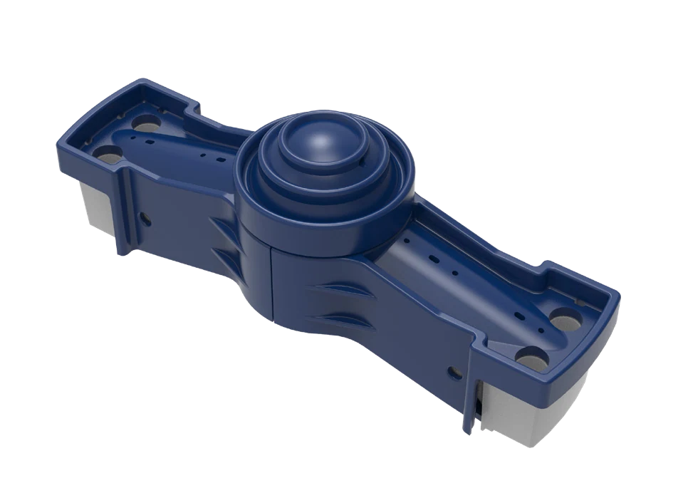
18
Spider Arm Shield
- Material Options
- High-manganese steel; martensitic wear-resistant cast steel; wear plate. Confirm hardness, tensile strength and other numerical properties against a material specification, manufacturer data or approved project record before publishing.
- Installation and Function
- Top and sides of the spider arms
- Maintenance Category
- Core Protection Part
17
Spider Cap
- Material Options
- High-strength cast steel; high-manganese steel; impact-resistant cast-steel. Confirm hardness, tensile strength and other numerical properties against a material specification, manufacturer data or approved project record before publishing.
- Installation and Function
- Top center of the spider, resisting direct impact from large rocks
- Maintenance Category
- Top Wear Part
19
Spider Bushing
- Material Options
- Leaded tin bronze such as C93200, or OEM-specified bearing bronze
- Installation and Function
- Center bore of the spider, guiding and supporting the upper end of the mainshaft
- Maintenance Category
- Critical Sliding Wear Part
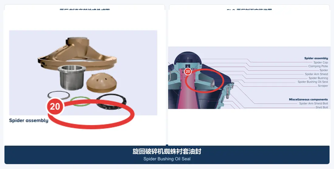
20
Spider Bushing Oil Seal
- Material Options
- NBR, HNBR, FKM or PTFE composite seal
- Installation and Function
- Boundary of the spider-bushing lubrication cavity
- Maintenance Category
- Replaceable Seal
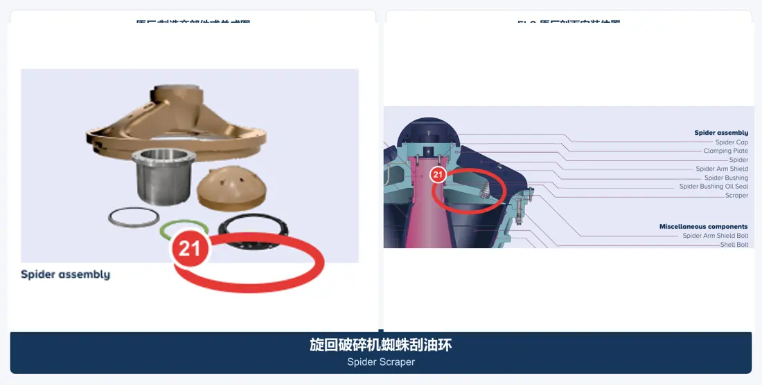
21
Scraper
- Material Options
- Wear-resistant copper alloy, quenched-and-tempered steel or oil-resistant polymer, according to the OEM construction
- Installation and Function
- Near the spider bushing, removing contaminants and controlling the lubricating-oil film
- Maintenance Category
- Replaceable Oil-Scraping Part
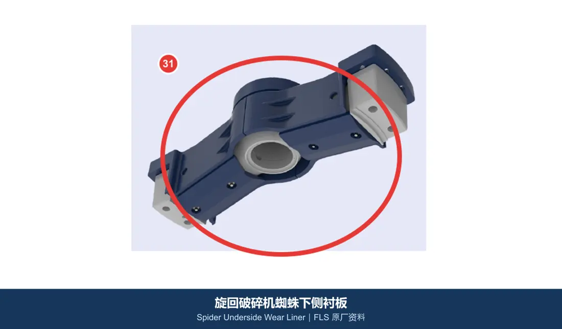
31
Spider Underside Wear Liner
- Material Options
- High-manganese steel, martensitic wear-resistant cast steel or quenched and tempered wear plate
- Installation and Function
- Underside of the spider for buried-feed and highly abrasive conditions
- Maintenance Category
- Additional Wear Part
22
Concaves
- Material Options
- High-manganese steels such as Mn18Cr2 and Mn22Cr2; OEM-approved composite/MMC options for specific duties
- Installation and Function
- Segmented fixed crushing surfaces inside the top shell
- Maintenance Category
- Key Wear Parts
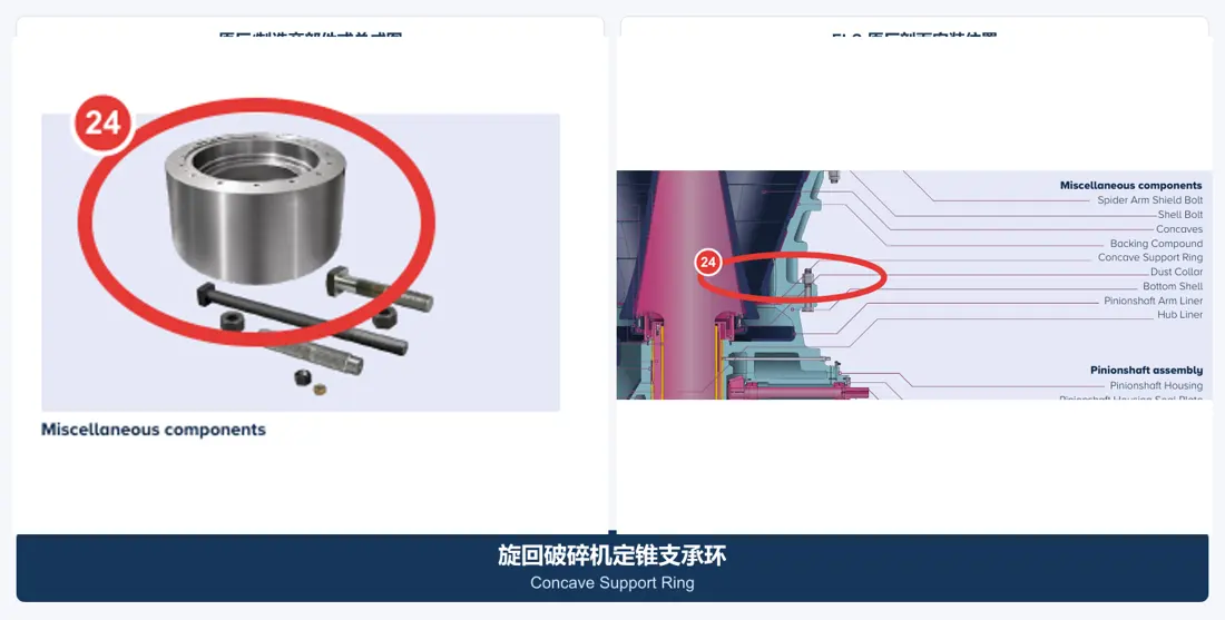
24
Concave Support Ring
- Material Options
- High-strength cast steel, forged steel or quenched-and-tempered alloy steel, according to OEM drawings
- Installation and Function
- Below the concaves, transmitting liner loads and maintaining the chamber position
- Maintenance Category
- Load-Carrying Wear Part
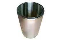
01
Mainshaft Sleeve
- Material Options
- Quenched-and-tempered alloy steels such as 42CrMo/4140 or 34CrNiMo6, according to OEM drawings
- Installation and Function
- Replaceable sleeve on the upper mainshaft, protecting the shaft and threaded or assembly surfaces
- Maintenance Category
- Replaceable Protection Part
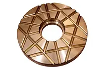
10
Mainshaft Step Plate
- Material Options
- High-strength copper alloy, steel-backed copper alloy or OEM-specified thrust material
- Installation and Function
- Axial load-bearing surface at the bottom of the mainshaft
- Maintenance Category
- Thrust Wear Part
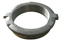
02
Head Nut
- Material Options
- Quenched-and-tempered alloy steel or cast steel, according to OEM drawings
- Installation and Function
- Secures the mantle and transmits preload
- Maintenance Category
- Maintenance Replacement Part
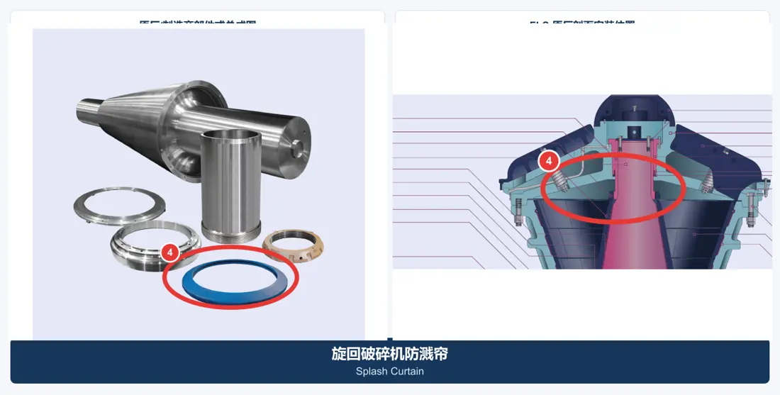
04
Splash Curtain
- Material Options
- Oil-resistant rubber, polyurethane, reinforced elastomer or OEM composite material
- Installation and Function
- Mainshaft/top-shell area, blocking fragments, slurry and dust splash
- Maintenance Category
- Replaceable Seal-Protection Part
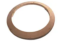
05
Dust Seal
- Material Options
- NBR, HNBR, PU, FKM or OEM-specified elastomer
- Installation and Function
- Dust interface between the mainshaft and top shell, protecting the lubrication zone
- Maintenance Category
- Replaceable Seal
07
Bottom Shell Bushing
- Material Options
- High-lead/tin bronze, aluminium bronze or OEM-specified bearing copper alloy
- Installation and Function
- Center bore of the bottom shell, supporting the eccentric and mainshaft system
- Maintenance Category
- Critical Wear Part
08
Gear
- Material Options
- Quenched-and-tempered 42CrMo/50CrMo4 steel or carburized steel such as 18CrNiMo7-6, according to the matched-pair design
- Installation and Function
- Around the eccentric assembly, meshing with the pinion
- Maintenance Category
- Critical Drive Part
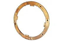
09
Eccentric Wear Plate
- Material Options
- Aluminium bronze, manganese bronze, tin bronze or steel-backed composite bearing material
- Installation and Function
- Axial contact surface of the eccentric assembly
- Maintenance Category
- Axial Wear Part
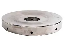
11
Step Washer
- Material Options
- High-strength copper alloy or OEM-specified thrust-bearing material
- Installation and Function
- Between the step plate and piston wear plate
- Maintenance Category
- Thrust Wear Part
12
Piston Wear Plate
- Material Options
- High-strength copper alloy, aluminium bronze or steel-backed composite material
- Installation and Function
- Above the hydraulic piston, carrying the axial load of the mainshaft system
- Maintenance Category
- Thrust Wear Part
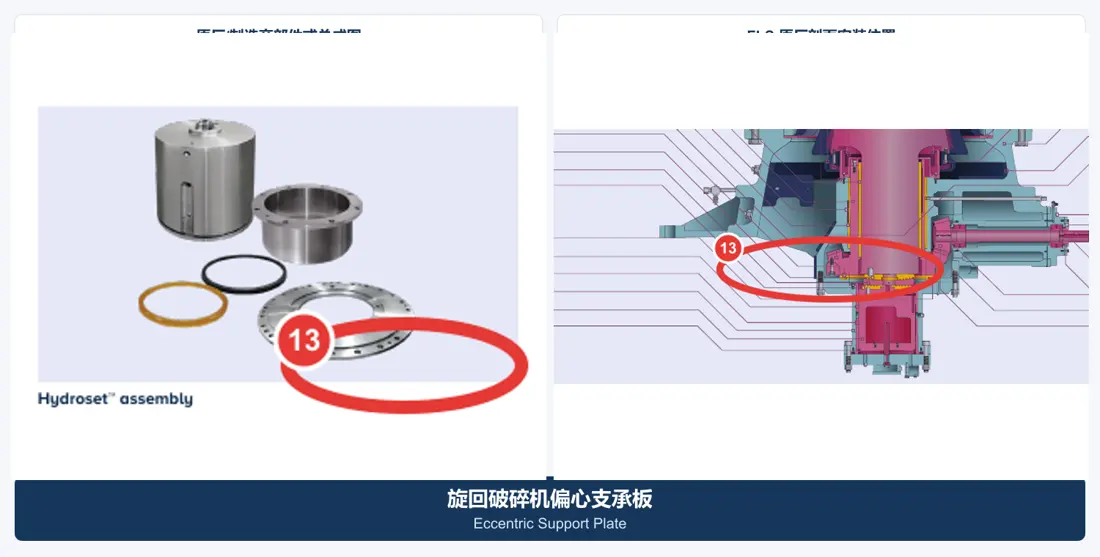
13
Eccentric Support Plate
- Material Options
- High-strength copper alloy, alloy-steel/copper composite construction or OEM-specified material
- Installation and Function
- Lower support surface of the eccentric assembly
- Maintenance Category
- Axial Wear Part
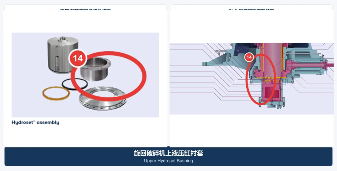
14
Upper Hydroset Bushing
- Material Options
- Centrifugally cast bearing bronze or OEM-specified copper alloy
- Installation and Function
- Upper guide in the hydraulic mainshaft-position system
- Maintenance Category
- Sliding Wear Part
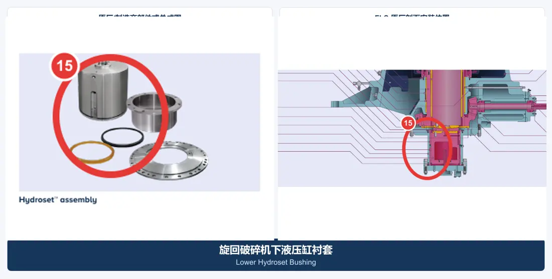
15
Lower Hydroset Bushing
- Material Options
- Centrifugally cast bearing bronze or OEM-specified copper alloy
- Installation and Function
- Lower guide and bearing surface in the hydraulic cylinder
- Maintenance Category
- Sliding Wear Part
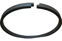
16
Hydroset Seal
- Material Options
- PU, NBR, HNBR or PTFE composite seal, or OEM seal kit
- Installation and Function
- Hydraulic cylinder/piston interface, retaining pressure and excluding contamination
- Maintenance Category
- Frequently Replaced Seal
23
Backing Compound
- Material Options
- Two-component, 100% solids epoxy-elastomer composite
- Installation and Function
- Fills the clearance between concaves or mantle and their supporting bodies
- Maintenance Category
- Installation Consumable
25
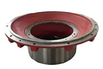
Dust Collar
- Material Options
- OEM-specified cast steel, ductile iron, copper alloy or wear-resistant composite material
- Installation and Function
- Bottom-shell dust interface, working with the seal to keep dust out of the lubrication zone
- Maintenance Category
- Dust-Control Wear Part
26
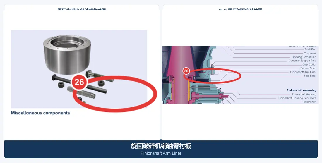
Pinionshaft Arm Liner
- Material Options
- High-manganese steel; wear-resistant cast steel; quenched-and-tempered wear plate. Confirm hardness, tensile strength and other numerical properties against a material specification, manufacturer data or approved project record before publishing.
- Installation and Function
- Near the bottom-shell pinion-shaft arm, protecting the shell from falling-material wear
- Maintenance Category
- Shell Protection Part
27
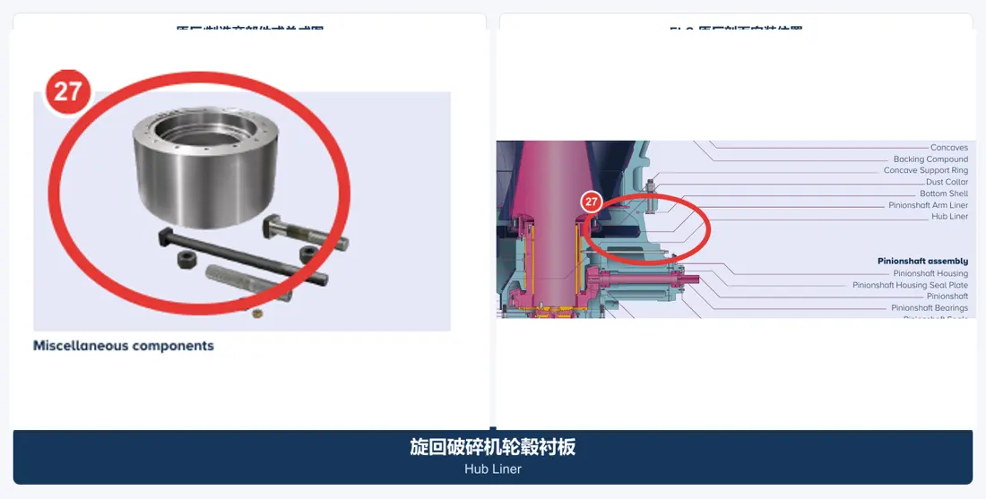
Hub Liner
- Material Options
- High-manganese steel, wear-resistant cast steel or quenched and tempered wear plate
- Installation and Function
- Bottom-shell hub area, protecting the structure around the eccentric assembly
- Maintenance Category
- Shell Protection Part
28
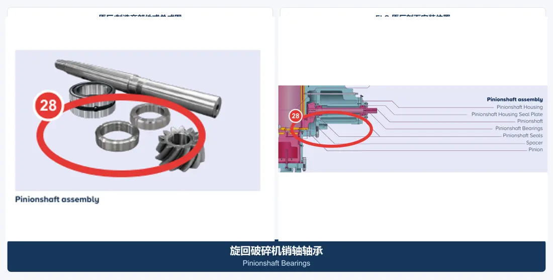
Pinionshaft Bearings
- Material Options
- Clean 100Cr6/SAE 52100 bearing steel and OEM-specified cage
- Installation and Function
- On both sides of the pinion shaft, maintaining gear center distance and rotational accuracy
- Maintenance Category
- Critical Rolling-Element Part
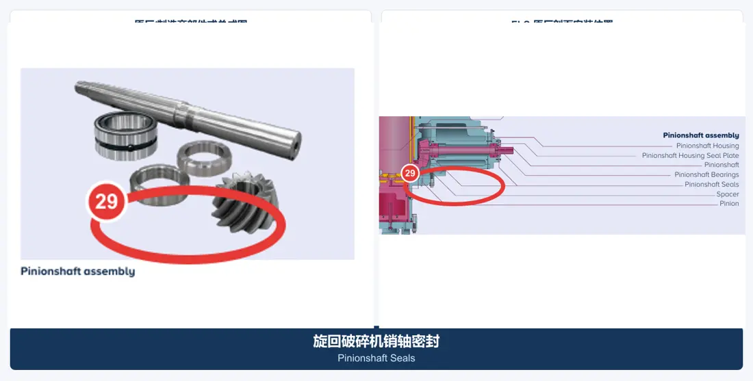
29
Pinionshaft Seals
- Material Options
- NBR, HNBR, FKM or PTFE composite seal
- Installation and Function
- At both ends of the pinion-shaft housing, retaining lubricant and excluding dust
- Maintenance Category
- Replaceable Seal
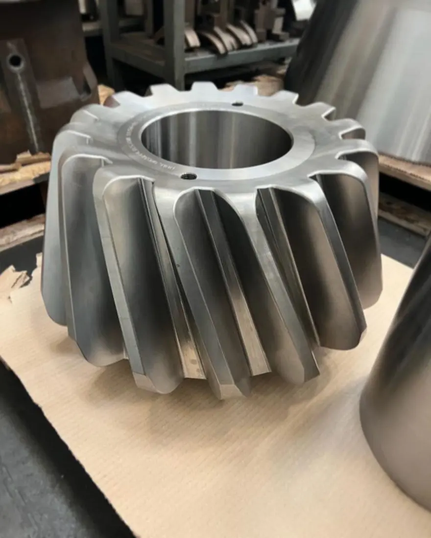
30
Pinion
- Material Options
- Carburized or quenched-and-tempered alloy steels such as 18CrNiMo7-6, 20CrMnTi and 50CrMo4, according to the OEM matched-pair design
- Installation and Function
- Inner end of the pinion shaft, meshing with the ring gear to drive the eccentric assembly
- Maintenance Category
- Critical Drive Part
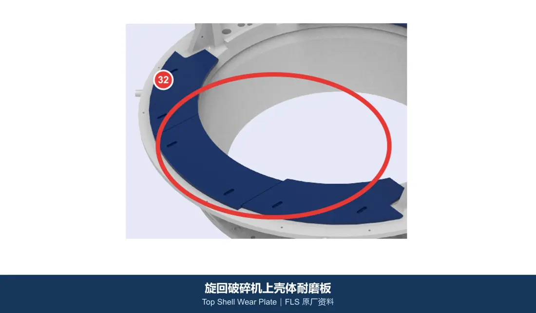
32
Top Shell Wear Plate
- Material Options
- High-manganese steel, wear-resistant cast steel or quenched and tempered wear plate
- Installation and Function
- Around the top-shell feed opening, protecting the shell with adjustable segments
- Maintenance Category
- Additional Wear Part
33
Feed Hopper Liner
- Material Options
- quenched-and-tempered wear plate; bimetal composite plate; ceramic composite; rubber liner. Confirm hardness, tensile strength and other numerical properties against a material specification, manufacturer data or approved project record before publishing.
- Installation and Function
- Feed hopper above the main machine, exposed to falling-rock impact and sliding wear
- Maintenance Category
- External Wear Part
34
Feed Chute Liner
- Material Options
- quenched-and-tempered wear plate; high-chromium hardfaced composite pla; ceramic/rubber composite. Confirm hardness, tensile strength and other numerical properties against a material specification, manufacturer data or approved project record before publishing.
- Installation and Function
- Inner surface of the feed chute, controlling material flow and protecting the parent steel structure
- Maintenance Category
- External Wear Part
5. Material Performance and Acceptance Boundaries
1. High-manganese steel liners are not accepted on hardness alone. Also verify chemical composition, solution heat treatment, grain-boundary carbides, impact toughness, casting defects, profile and mounting surfaces. Typical high-manganese steel starts at relatively low hardness but work-hardens substantially under impact and compression; simply increasing manganese content without enough impact does not necessarily extend service life. 2. Copper-alloy sliding pairs must be accepted as a matched system. Material grade, centrifugal-casting soundness, hardness, concentricity, cylindricity, oil grooves, surface roughness, interference and operating clearance are all required. Do not purchase them under the generic description “copper bush.” 3. Ring gears and pinions must be managed as a matched pair. Key checks include material cleanliness, forging quality, case depth/core properties, tooth profile and lead, runout, magnetic-particle/ultrasonic testing, contact pattern, backlash and spray lubrication. Do not replace one member without considering its mate and bearing clearances. 4. Select hydraulic bushes and seals for pressure, temperature and fluid compatibility. Confirm seal cross-section, hardness, compression set, extrusion gap, rod/bore surface finish and hydraulic-fluid compatibility. 5. Select spider caps, guards and shell liners according to the impact-to-abrasion ratio. Prioritize core toughness and reliable fastening in zones directly struck by large rocks; use harder quenched-and-tempered plate, hardfaced composite plate or ceramic-composite construction in continuous sliding-abrasion zones. 6. Crusher backing is a structural load-transfer material. Confirm volumetric shrinkage, compressive strength, impact absorption, curing temperature, working time, exotherm peak and removal process; do not substitute ordinary potting compound.
Materials for similarly named parts may differ by OEM, machine model and operating conditions. Confirm the machine model, drawing and measured dimensions before ordering or manufacture.