FLS FT Series / Fuller-Traylor Ball Mills

Identify FT Series and Fuller-Traylor installations, then review ball mill liners, discharge wear parts, girth gears, pinions, trunnions, main bearings and hydraulic lubrication spares. ANRANST coordinates drawing-based manufacturing in China, quality control and finished-part delivery.

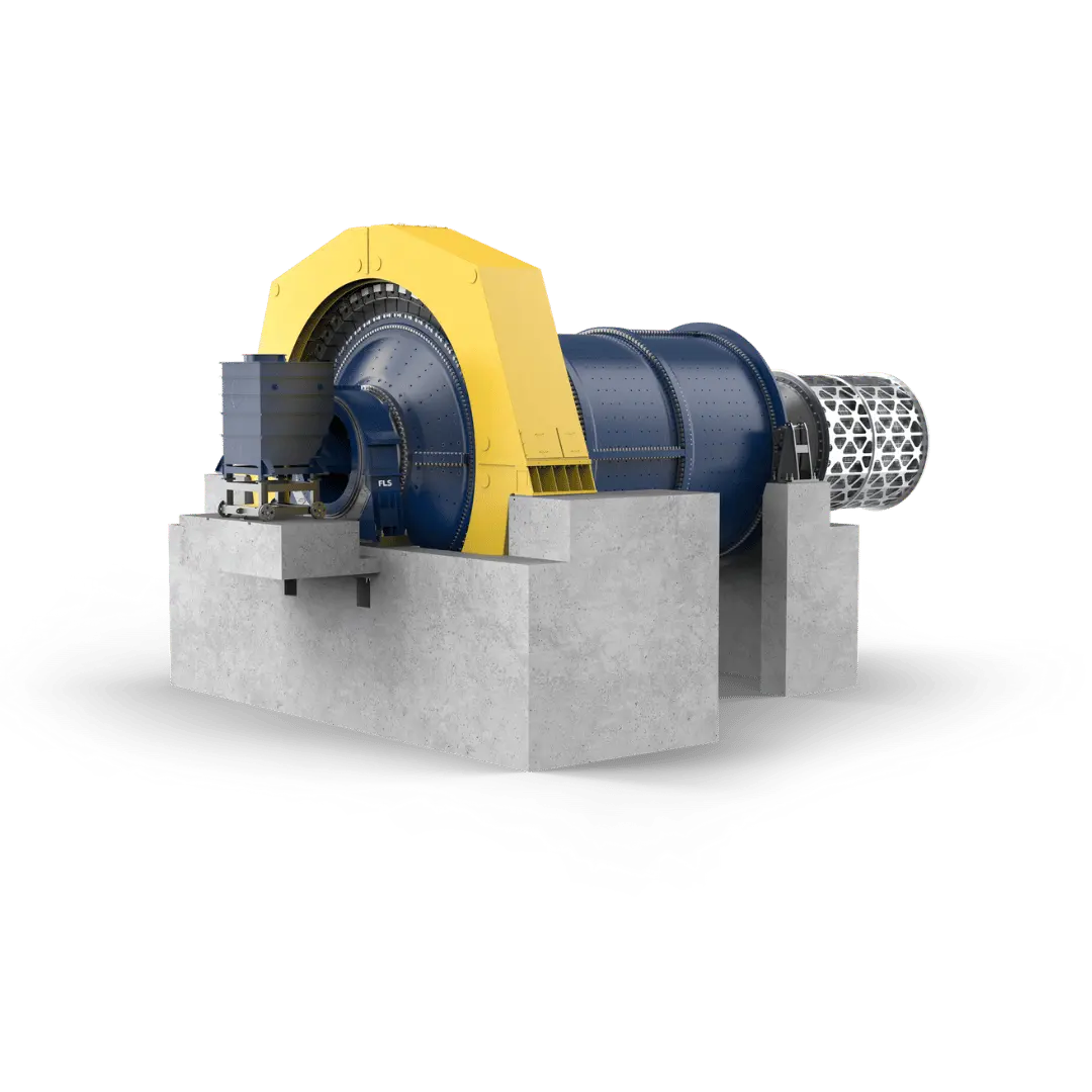
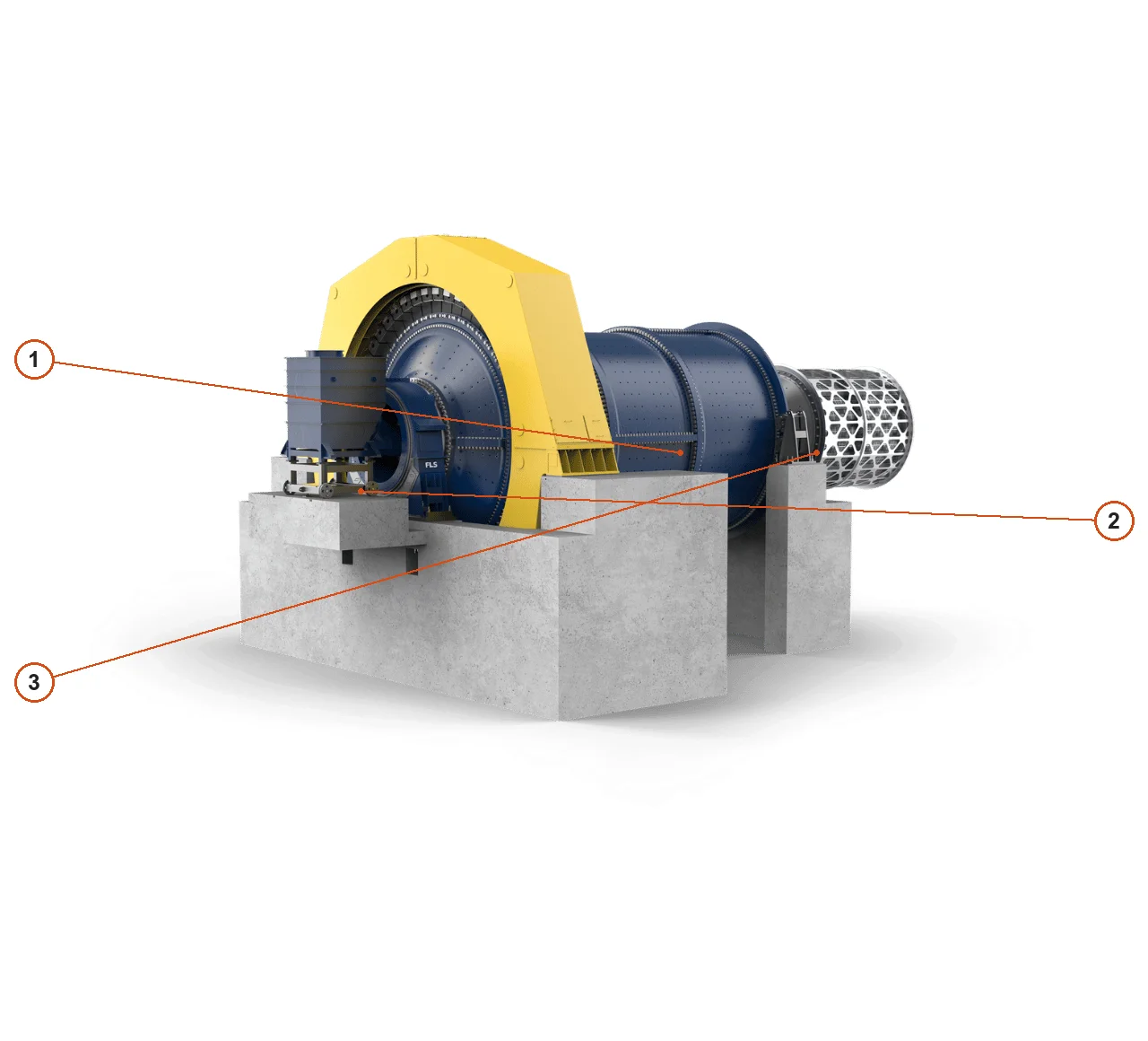
FLS ball mill machine image
Official FLS ball mill image, showing the shell, ends, trunnions, supports and drive positions.
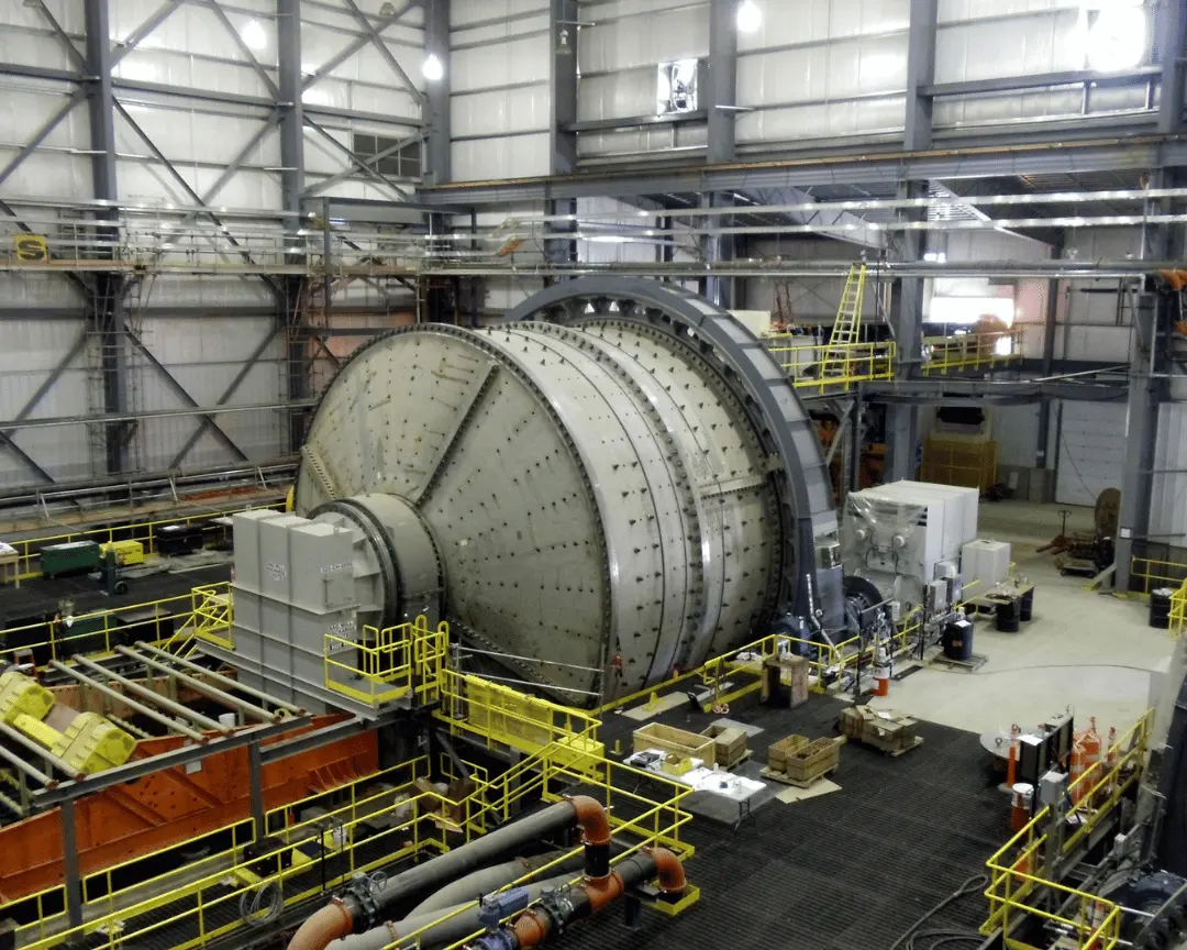
FLS ball mill site installation
Official FLS ball mill installation image for checking support, drive, platform and maintenance access arrangements.
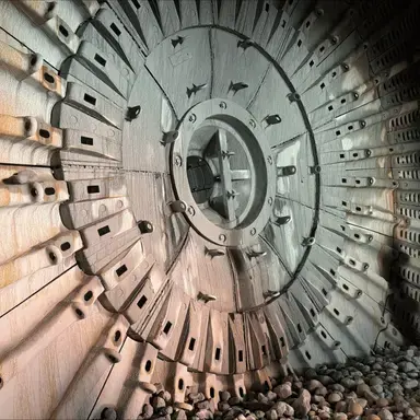
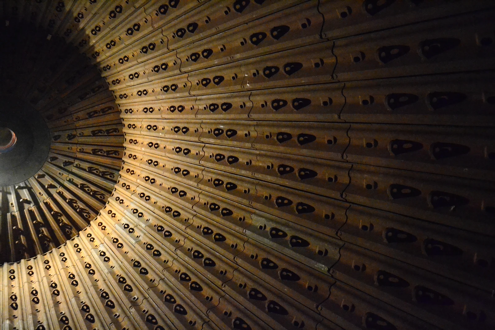
FLS horizontal mill internal liner system
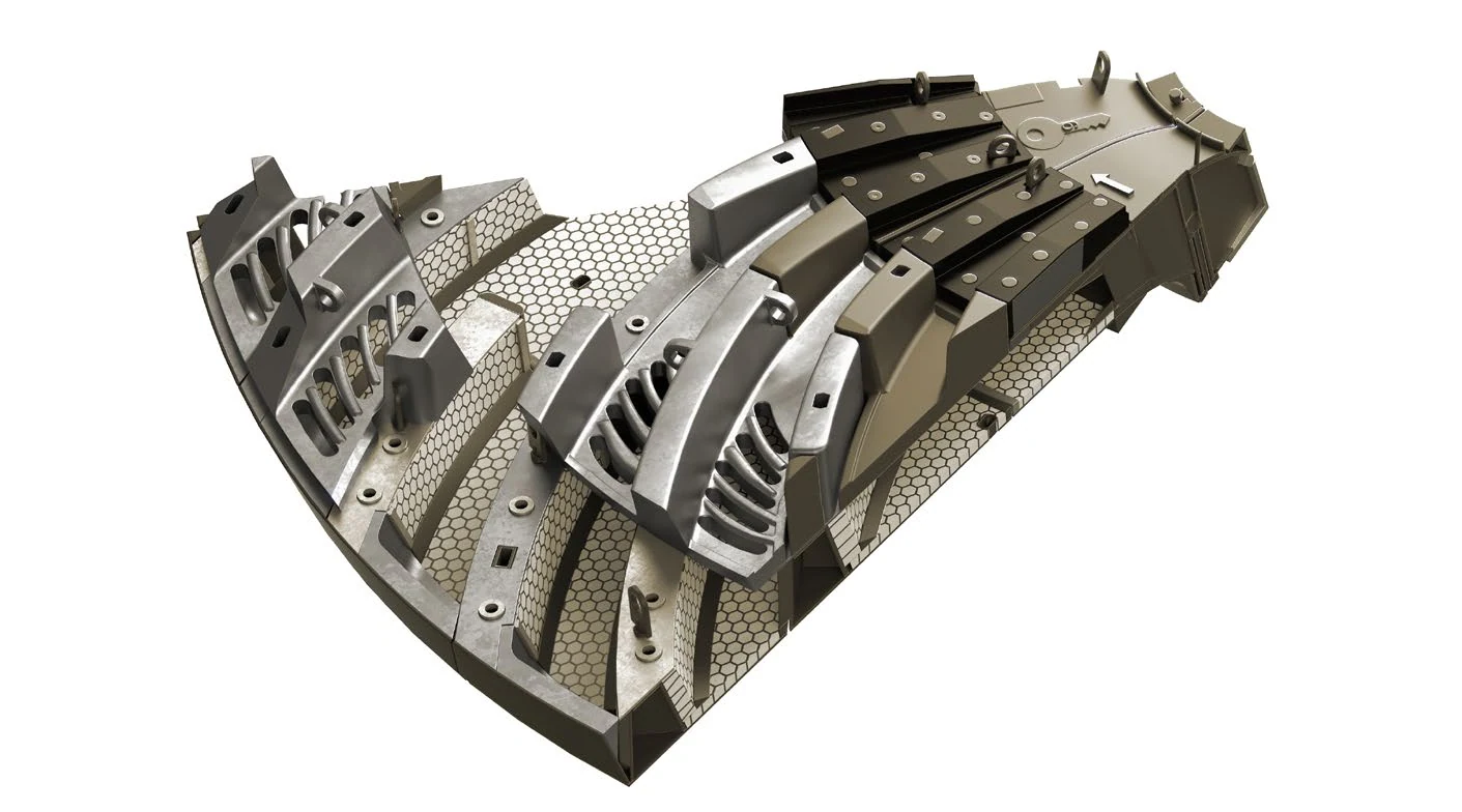
FLS horizontal mill internal liners and end structure, showing shell liners, lifter bars, end liners and discharge areas.
OEM equipment family

Confirm the series, dimensions and discharge structure before selecting parts

This page covers information relevant to spare part identification and supply: standard FT Series diameters, the current overall Fuller-Traylor ball mill range, support and drive configurations, and wear parts and core spares that ANRANST can help source.

FT Series Standard modular series
1.6–4.3 m Standard FT Series diameter
1.6–8.5 m Current FLS ball mill diameter range
≤22,000 kW Current published maximum power
Models and key dimensions

Ball mill families and installed configurations

Only series, diameters and power ranges verifiable on the current FLS website are listed. Confirm full specifications for project-specific mills against the nameplate, serial number, general arrangement drawing and equipment records.

Series / configurationKey dimensions and powerDischarge and identification notes
FT Series — Ball MillStandard diameter 1.6–4.3 mWet or dry; trunnion overflow, grate, peripheral or air-swept discharge
Fuller-Traylor Ball MillDiameter 1.6–8.5 m; power up to 22,000 kWProject-specific series; identify by nameplate, general arrangement drawing, serial number and drive configuration
Fuller-Traylor Overflow Ball MillWithin the current 1.6–8.5 m ball mill rangeOverflow discharge; confirm shell length, power and support arrangement against project documents
Fuller-Traylor Grate Discharge Ball MillWithin the current 1.6–8.5 m ball mill rangeGrate discharge; check grates, pulp lifters and discharge end structure

Data sources:Current FLS Ball mills page and Current FLS Grinding product overview. Manufacturing spares still requires confirmation of the serial number, drawing number, drawing revision and physical interfaces.

Wear Parts

Liners and discharge wear systems

The current FLS ARMOUR® horizontal mill liner range includes steel, rubber and composite solutions. Select the material for each position according to impact, abrasion, slurry erosion, weight and maintenance objectives.

Shell Liners
01

Shell Liners

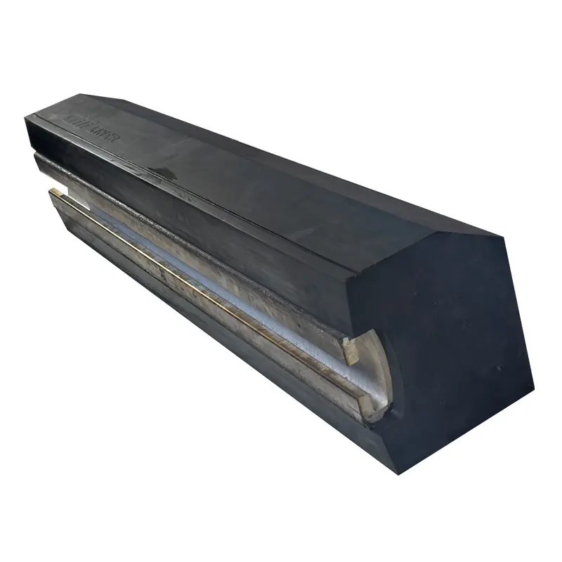
Shell Liners / Shell Plates

Shell liners protect the shell interior and control grinding media movement. Check mill diameter, shell length, layout, hole patterns, thickness, individual weight and fastening method. The image illustrates a general part category.
Lifter Bar / Lifter Plate
02

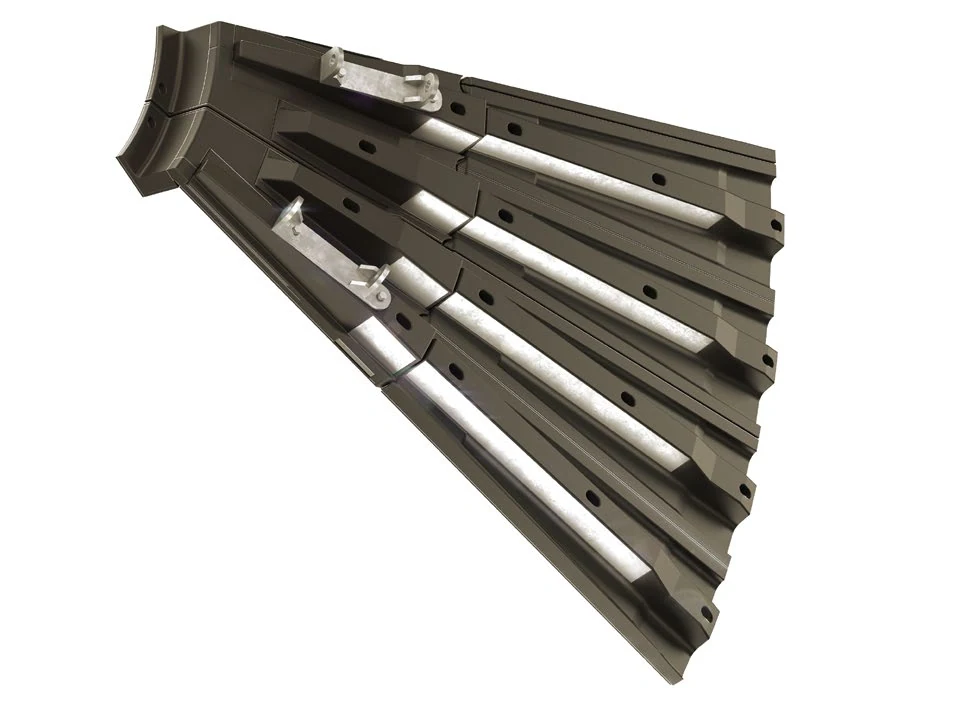
Lifter Bar / Lifter Plate

Lifter Bars / Lifter Plates

Lifter bars work with shell liners to control lifting trajectories and withstand repeated impact and abrasion. Check cross-section, lift height, layout angle, wear direction and connecting structure. The image illustrates a general part category.
End Liners
03

End Liners

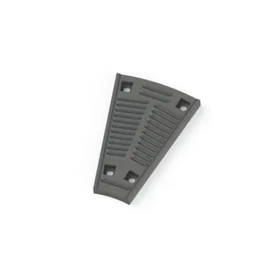
Head / End Liners

End liners fit inside the feed or discharge head and withstand impact from balls, ore and slurry. Distinguish feed/discharge ends, inner/outer rings, hole patterns, profiles and relationships with adjacent liners. The image illustrates a general part category.
Discharge Grate
04

Discharge Grate

Discharge Grates

Grates allow slurry to pass while retaining grinding media in grate-discharge mills. Check grate type, opening dimensions, flow passages, end position, layout and anti-blockage requirements. The image illustrates a general part category.
Pulp Lifters
05

Pulp Lifters

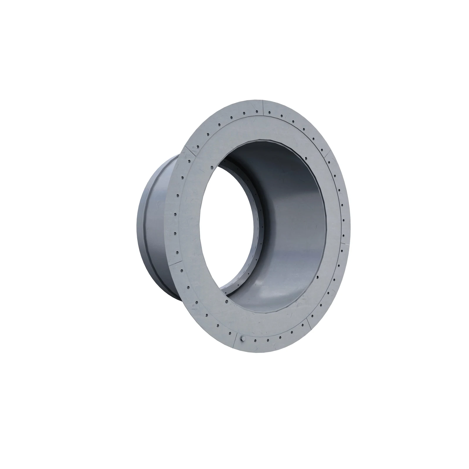
Pulp Lifters / Discharge Lifters

Located behind the discharge grates, pulp lifters guide slurry into the discharge trunnion. Check flow direction, inner/outer lifters, end position, holes and grate interfaces. The image illustrates a general part category.
Trunnion liner
06

Trunnion Liners

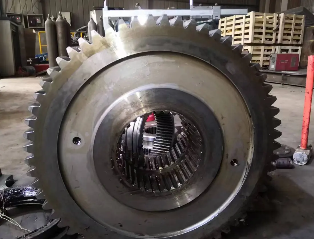
Mill Trunnion Liners

Trunnion liners fit inside the feed or discharge trunnion bore, protecting it and forming the material passage. Check end position, internal profile, length, flange hole pattern, seals and connecting structure. The image illustrates a general part category.
Spare Parts

Drive, load-bearing and system spares

FLS's current public mill spares range includes girth gears, trunnions, seals, hydraulic components, filters and sensors. This page also provides drawing-based identification for main bearings, mill heads, drives and critical fasteners.

Ball mill girth gear identification image
01

Girth Gear

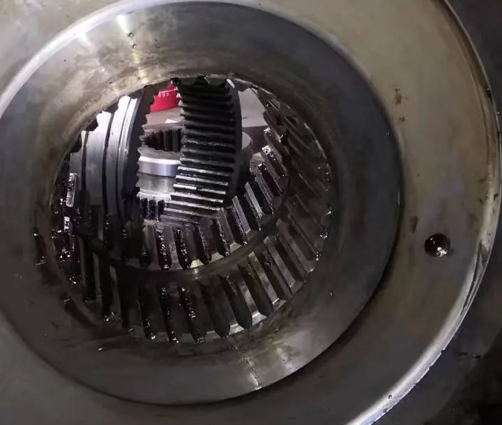
Girth Gear / Ring Gear

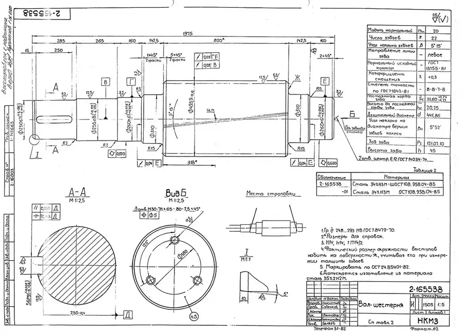
A core transmission component on gear-driven ball mills. Check module, tooth count, pressure angle, face width, split construction, centre distance, helix direction, mating marks and heat treatment requirements.

View Part Details →
Ball mill drive pinion identification image
02

Drive Pinion

Drive Pinion

Check the pinion together with the girth gear. Confirm tooth geometry, journals, bearing seats, keyways or connections, tooth accuracy, heat treatment and meshing direction.

View Part Details →
Main Bearings, Bearing Liners and Housings
02

Main Bearings, Bearing Liners and Housings

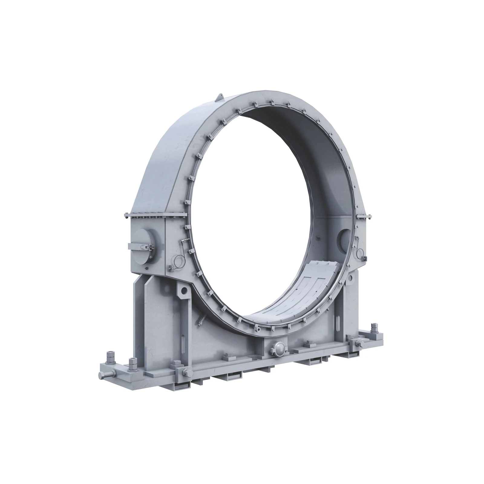
Main Bearings, Bushings & Housings

These components support the trunnions and rotating assembly. Check journal diameter, fixed/floating end, hydrostatic or hydrodynamic design, bearing liner material, oil passages, seals and installation elevation. The image illustrates a general part category.
View General Part Details →
Trunnions and mill heads
03

Trunnions and Mill Heads

Trunnion & Mill Head

These large load-bearing structures connect the shell, main bearings and feed/discharge passages. Check end position, journals, flange hole patterns, materials, non-destructive testing, machining datums and liner interfaces. The image shows the FLS ball mill structure.

Submit Drawings for Technical Confirmation →
Drive and coupling assemblies
04

Drive and Coupling Assemblies

Drive Train & Couplings

These cover high-speed motors with reducers, low-speed motors directly coupled to pinions, or gearless drive interfaces. Check power, speed, reduction ratio, coupling, braking and installation datums. The image illustrates general horizontal mill drive parts.

Submit Drawings for Technical Confirmation →
Seals, hydraulic and lubrication parts
05

Seals, Hydraulic and Lubrication Parts

Seals, Hydraulics & Lubrication Parts

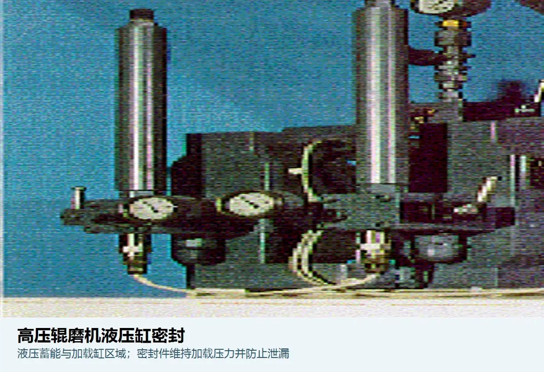
The current FLS mill spares range includes seals, hydraulic components, oil filters and sensors. Confirm against specific system diagrams, interfaces, pressure, fluid and original-part markings. The image illustrates the hydraulic seal category only.

Submit Drawings for Technical Confirmation →
Critical fasteners and connectors
06

Critical Fasteners and Connectors

Critical Bolting & Hardware

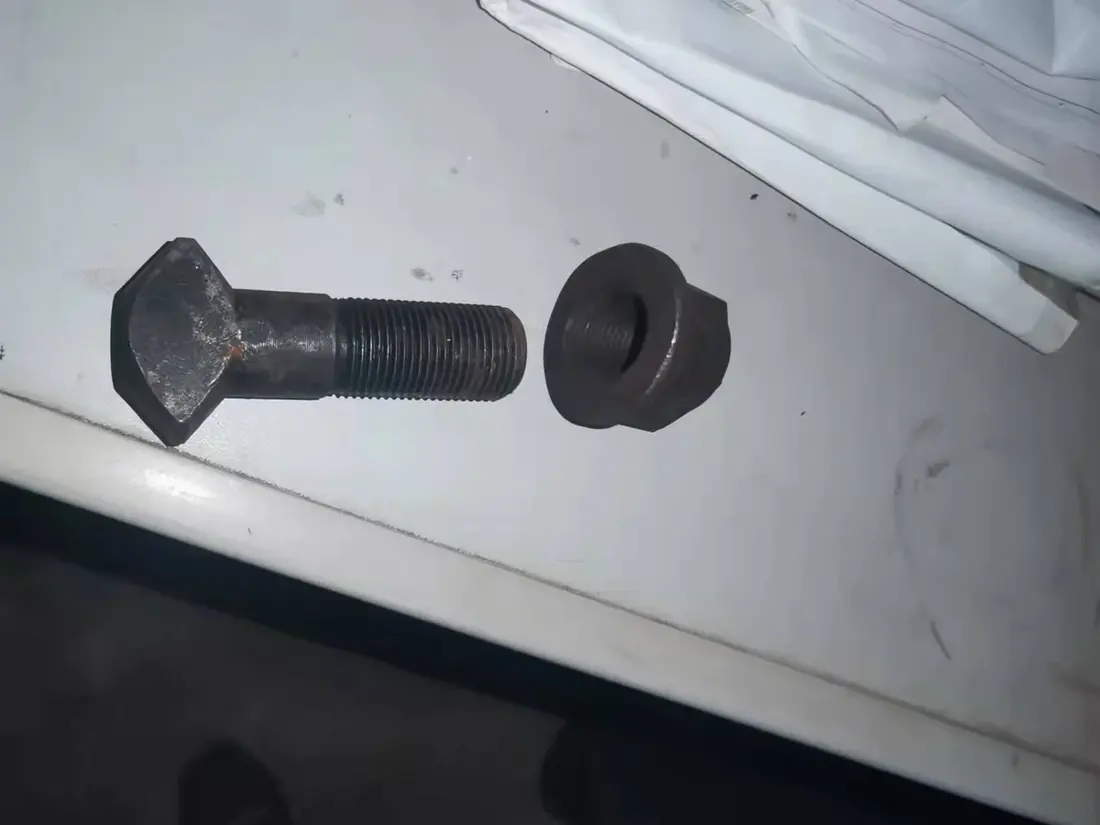
These parts connect shell flanges, liners and rotating assemblies. Check thread specification, effective length, material grade, preload method, locking structure, washers and assembly/removal access. The image shows an ANRANST fastener product category.

Submit Drawings for Technical Confirmation →

Number checks: if you have an FLS, Fuller-Traylor or third-party drawing number, submit it with the ball mill specifications, serial number, part position, drawing revision and used-part photos. Verified number cross-references are recorded on the relevant part page.

What information is needed for an FLS ball mill spare parts enquiry?

Provide the FT Series or Fuller-Traylor family, complete specifications, serial number, support and drive arrangements, part position, drawing or part number, drawings, current-part photos and operating conditions.

Is mill diameter enough to identify liners?

No. Also check shell length, feed/discharge end, liner layout, hole patterns, fastening method, discharge structure, drawing revision and physical interfaces.

How are existing OEM or third-party drawing numbers checked?

Submit the drawing number, matching equipment specifications, serial number, installation position, drawing revision and used-part information. These allow checks against the equipment BOM, structural dimensions and applicable installation.

Submit FLS ball mill specifications, drawing numbers or drawings

Provide the FT Series or Fuller-Traylor family, diameter, length, drive and support arrangements, nameplate, serial number, current-part photos, drawings, material and operating conditions. We use these to identify parts, assess materials, organize production at certified foundries, control quality and deliver finished components.

Manufacturing Services in China

From Technical Assessment to Finished-Part Delivery

ANRANST provides customers worldwide with engineering assessment, production at certified foundries to drawing, quality control and finished-part delivery for custom wear parts and industrial spares, with scope to support other custom industrial parts.

01

Drawing and Engineering Review

We review mating surfaces and interface dimensions and assess material, heat treatment and manufacturing feasibility.

02

Material and Heat-Treatment Specification

Material grades and heat-treatment processes are specified order by order, confirmed in the technical agreement and tracked through production.

03

Quality Control

Drawing confirmation, material and process control, production tracking, inspection and acceptance coordination.

04

Finished-Part Delivery

We coordinate manufacturing, quality confirmation, packaging and delivery of complete finished parts in a workable, closed-loop supply process.

Provide the existing model, drawings, drawing or part numbers, materials or operating conditions so we can identify the appropriate technical review and supply route.

Submit an Enquiry