
BALL MILL END LINER / HEAD LINER
Ball Mill End Liners
Feed and Discharge End Protection · Identified by End, Ring and Position
End liners fit inside the ball mill heads and withstand impact and abrasion from balls, material and slurry. ANRANST provides end and position identification, material assessment, drawing review, quality control and delivery of matched sets.
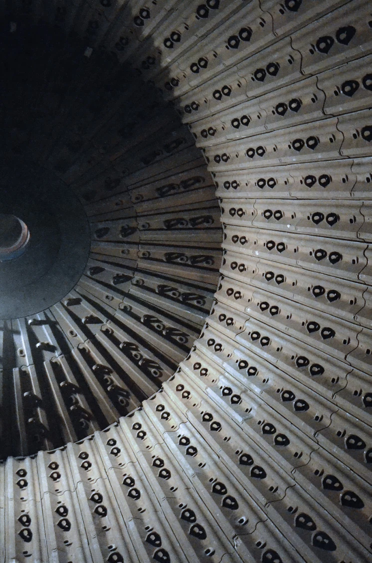
Part Function Mill End Identification Feed end, discharge end, rotation and viewing direction Ring Position Inner, intermediate or outer ring, sector and position number Structural Interfaces Head profile, bolt pattern, adjacent parts, clearances and seating Complete Sets End liners, bolts, washers, seals, identification and arrangement drawing
Protect the head and connect shell, feed and discharge liner systems
End liners are usually segmented by sector, ring and position. They protect the head and form a continuous working surface with shell liners, trunnion liners, grates or feed structures.
Similar outlines do not establish interchangeability. Feed or discharge end, inner or outer ring, grate or overflow discharge, handedness and site modifications all determine part identity.
Position and Performance
Mill end and radial position determine loads and material requirements
Record wear, impact, erosion and fastening condition separately for the feed and discharge ends and for inner and outer rings.
Feed End Outer Ring
Joins the shell liners and is exposed to larger particles and grinding media. Check concentrated impact, steps and uneven end wear.
Feed End Inner Ring
Near the feed trunnion or feed structure. Check material flow, local erosion, interfaces and fastening access.
Discharge End Outer Ring
Joins the shell and discharge system. Check slurry flow, adjacent grates or transition plates and uneven wear.
Discharge End Inner Ring
Near the discharge trunnion and slurry passages. Check erosion, blockage, clearances and adjacent pulp lifter interfaces.
Hole areas and rear surface
Carry preload and structural loads. Check cracks around holes, crushed seating surfaces, rear contact and slurry leakage.
Sector Edges
Gaps and steps between adjacent plates change wear and loading. Check orientation, layout, edge wear and installation sequence.
Materials and Manufacturing Processes
Select Materials for End Impact, Erosion and Support
Material families support initial selection. Confirm grade, properties, heat treatment and geometry by mill end, position and drawing.
Selection sequence: mill end and ring position → impact, erosion and support → existing failures → material and process → drawings and acceptance requirements.
Failure Diagnosis
Check the mill end, position and adjacent systems together
Similar wear patterns at the feed and discharge ends may have different causes.
| Observed condition | Priority checks | Improvement Options |
|---|---|---|
| Rapid Outer Ring Wear or Steps | Shell transition, adjacent plate heights, impact position, layout, material and uneven end flow | Restore a continuous working surface and optimise thickness and material by sector |
| Inner Ring Erosion or Grooves | Feed and discharge flow, trunnion interfaces, slurry velocity, clearances, blockage and material | Improve flow channels, interfaces and erosion resistance |
| End Liner Fracture | Impact, head support, rear profile, hole positions, preload, hardness and manufacturing defects | Improve toughness, restore seating and apply suitable nondestructive inspection |
| Hole Cracks, Loosening or Slurry Leakage | Clamping length, bolt head shape, washers, seals, rear seating, preload and retightening | Restore the end liners, fasteners and seals as a system |
| Uneven Wear between Adjacent Sectors | Position numbers, orientation, gaps, uneven feed or discharge flow, material batches and heat treatment | Map end wear by position and improve individual zones |
Drawings and Inquiry Details
Identify the Mill End, Ring and Position before Checking Drawings
Provide the drawing, sample, spare model details or customer drawing for the specific sector, with its revision.
Equipment identification
OEM, series, full model, serial number, shell diameter, EGL, discharge type and modification history.
Mill End and Position
Feed or discharge end, inner or outer ring, sector, position number, orientation, quantity and arrangement drawing.
Drawing and Revision
drawing, spare model details, drawing revision, project number and markings on the part.
Key dimensions
Inside and outside diameter, sector angle, thickness, rear profile, hole spacing and diameter, counterbores, outline and weight.
Adjacent Interfaces
Shell liners, trunnion liners, grates, pulp lifters, bolts, washers, seals and clearances.
Materials and Operating Conditions
Current material, properties, service life, end wear map, balls, slurry, throughput and failure photographs.
Related Equipment and Parts
End Liners, Discharge Systems, Equipment, OEMs and Materials
Review positions and materials, identify the installed OEM series, then confirm drawing and end layout.
Ball Mill Lining System View the complete shell, lifter, discharge and trunnion liner system. Discharge Grate Check adjoining grates, flow channels and interfaces at the grate-discharge end. General Ball Mills Information Review machine layout, discharge type and part positions. Metso Ball Mills Identify end liners by Select / Premier model and dimensions. FLS Ball Mills Identify drawing from the brand, equipment series and installed-machine details. Wear-Resistant Alloy Steel Review material properties, heat treatment and acceptance requirements.