
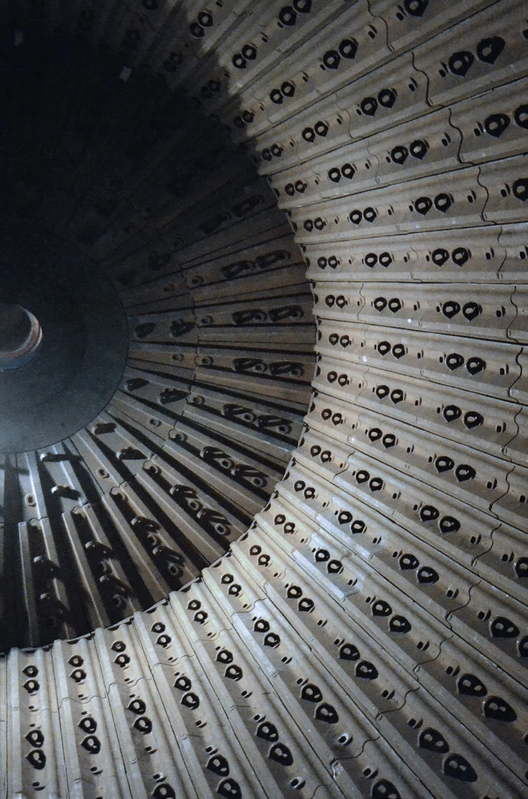
Metso Select™ / Premier™ Ball Mills

Identify the installation by series, diameter, EGL, drive and drawings, then confirm liners, end components, discharge parts, girth gears, pinions, main bearings, drive components and ball mill relining equipment for quotation.

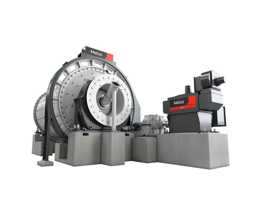
Metso Select gear-driven ball mill, manufacturer image
Manufacturer image of a Metso Select™ gear-driven ball mill, showing the shell, heads, trunnions and girth gear and pinion drive.
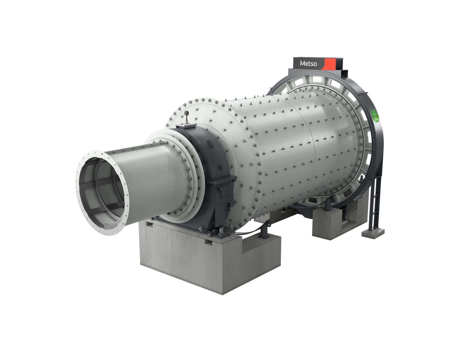
Metso Select ball mill liner system, manufacturer cutaway
Manufacturer cutaway of a Metso Select™ ball mill, showing shell liners, lifter bars, heads and discharge-end liners.
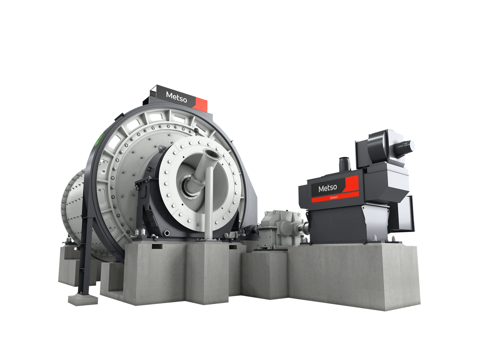
Rear view of a Metso Select gear-driven ball mill, manufacturer image
Manufacturer image of a Metso Select™ ball mill, showing the main motor, reduction gearing, low-speed coupling and gear-drive interfaces.
OEM Equipment Reference

Identify wear parts, spares and tooling by mill dimensions and drive configuration

This page supports spare-part identification and supply for Metso ball mills; it does not replace the manufacturer's equipment manual. Select™ is a pre-engineered horizontal mill series, while Premier™ mills are configured for individual projects. Before manufacturing liners, drive parts or load-bearing components, verify the complete model, nameplate / serial number, shell diameter, EGL, drive arrangement, feed and discharge ends, OEM drawing number, drawing revision, used-part photographs and actual interfaces.

41 models Select™ pre-engineered ball mill models published by the manufacturer
0.60–6.00 m Published Select™ diameter range
0.90–12.00 m Published Select™ EGL range
2.2–7,800 kW Published Select™ power range
Standard Models and Key Dimensions

Published Select™ range and identification of project-specific Premier™ mills

Only the published series and key dimensions needed for spare-part identification are listed. Current Metso Select™ information covers 41 pre-engineered ball mill models and their overall ranges. Dimensions, power ratings and part numbers not assigned to individual models in the current public information are not presented as fixed models. Premier™ configurations require confirmation from project records.

Equipment seriesStandard models / key dimensionsKey spare-part identification checksProduct status
Metso Select™ Ball Mills41 pre-engineered models; diameter 0.60–6.00 m; EGL 0.90–12.00 m; power 2.2–7,800 kWCheck the nameplate model, diameter, EGL, actual roller / gear drive arrangement, feed and discharge ends, liner layout and OEM drawingsCurrent published product range
Metso Premier™ project-specific ball millsProject-specific horizontal ball mills; the current public manufacturer page does not provide a universal standard model table for direct spare-part replacementEstablish correspondence using the project data sheet, nameplate, serial number, general arrangement, drive layout, liner drawings and used-part interfacesCurrent project-specific solutions

The 41 models and dimensional ranges narrow identification; they do not form a parts interchange list. Submit the complete nameplate, diameter, EGL, drive, feed and discharge ends, drawing number / drawings, used-part photographs and interface dimensions. Do not apply the Select™ range to Premier™ or modified equipment.

Wear Parts

Liner systems: identify the position, operating conditions and material requirements

Ball mill wear parts are grouped by shell, feed end, discharge end and material flow passages. This page provides a starting point for location and performance screening. Materials, geometry, hole patterns, thickness, weight, heat treatment and service life must be confirmed against ore, grinding media, particle size, wear records and drawings.

Metso mill liners, manufacturer image showing shell liners and lifter bars
01

Shell Liners and Lifter Bars

Shell Liners & Lifter Bars

Installed on the shell's inner wall, these parts protect the shell and establish the lifting and falling trajectory of the grinding media. Check shell diameter, EGL, individual liner profile, lifter height, layout, hole pattern, fastening method, wear direction and adjacent-part interfaces.

Material selection: Screen material candidates against impact, abrasive wear, grinding media, temperature and liner construction. Metal, rubber and composite liners are not interchangeable by name alone.

View the common part page →
Metso Select ball mill manufacturer cutaway showing feed-end liners and head protection
02

Feed-End Liners and Head Protection

Feed-End Liners & Head Protection

Located on the feed head, feed opening and adjoining shell-liner area, these parts withstand falling material, grinding media and slurry impact. Check the feed end, head design, inner and outer liner rings, opening profile, hole pattern, fastening and feed-chute interface.

Material selection: Material selection for end components must consider impact, sliding wear, corrosion, cast / welded construction and site installation and removal conditions.

View the common part page →
Metso Select ball mill manufacturer cutaway showing the discharge grate and pulp lifter area
03

Discharge Grates and Pulp Lifters

Discharge Grates & Pulp Lifters

For grate-discharge ball mills or mills with the corresponding discharge arrangement. Verify the discharge type, end location, openings / flow passages, lifter direction, inner and outer rings, hole pattern, discharge arrangement and trunnion interface. Do not apply this combination to an overflow configuration.

Material selection: Select grate and flow-passage materials and manufacturing methods according to slurry flow, grinding-ball retention, blockage, abrasion and local impact risks.

View the common part page →
Spare Parts

Gear drive, support and feed / discharge interface components

This section covers girth gears and pinions, mill heads and trunnions, main bearings / bearing shells / housings, main motors / gearboxes / couplings, feed chutes and discharge trommels. Confirm each against the installed ball mill configuration and drawings; do not infer it from a wear-part name or generic model.

Metso Select gear-driven ball mill, manufacturer image showing the girth gear and pinion drive
01

Girth Gear, Pinion and Gear Drive

Girth Gear, Pinion & Gear Drive

For gear-driven installations. Confirm that the mill actually uses this drive arrangement, then check module, tooth count, pressure angle, face width, helix direction, segmentation, shaft bore, center distance, tooth surface treatment, lubrication and connections.

Material selection: Confirm gear and pinion requirements against load, fatigue, lubrication, accuracy, tooth heat treatment and inspection criteria.

View the common part page →
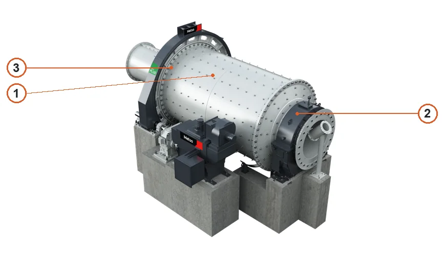
Metso Select ball mill rear view showing the head, trunnion and main bearing area
02

Mill Heads, Trunnions and Main Bearing Housings

Mill Heads, Trunnions & Main Bearing Housings

These large load-bearing components connect the heads, shell, feed / discharge passages and main bearings. Check the feed or discharge end, journal, flanges, hole pattern, bearing design, fixed / floating end, oil passages, seals, machining datums and nondestructive testing requirements.

Material selection: Confirm trunnion, bearing housing and plain-bearing materials against load, lubrication, temperature, fits, tolerances, heat treatment and inspection requirements.

View the common part page →
Metso Select gear-driven ball mill rear view showing motor, gearbox and coupling interfaces
03

Main Motor, Gearbox, Couplings and Auxiliary Drive

Motor, Gearbox, Couplings & Auxiliary Drive

Confirm the main motor, gearbox, high- and low-speed couplings, brake, inching drive and lubrication interfaces against the installed drive arrangement. Provide power, speed, ratio, torque, mounting, shaft ends, coupling type, controls and rotation direction.

Material selection: Confirm drive shafts, gears, couplings and connections against torque, fatigue, accuracy, heat treatment, lubrication and inspection requirements.

View the common part page →
Metso Select ball mill manufacturer cutaway showing feed and discharge interfaces
04

Feed Chute, Discharge Trommel and Critical Connections

Feed Chute, Trommel & Critical Interfaces

Current Metso Select™ information lists feed chute / spout and discharge trommel options. For quotation, verify whether they are fitted, then check interface flanges, seals, liners, supports, screening media, maintenance clearance and connections to adjacent equipment.

Material selection: Confirm flow-path liners, connections and seals separately according to material handled, wear, corrosion, vibration, temperature and installation space.

View the common spare-parts catalogue →
Special Tooling

Relining equipment with manufacturer-confirmed ball mill applications

Only the Tube Mill Reline Machine, which Metso's current website explicitly identifies for smaller SAG and ball mills, is shown. Applicability of other relining machines, bolt tools and transport equipment requires the specific ball mill dimensions, openings, liners, lifting requirements and site layout.

Metso Tube Mill Reline Machine, manufacturer image
01

Tube Mill Reline Machine for Smaller SAG / Ball Mills

Tube Mill Reline Machine

Metso's current product page describes Tube MRM as a compact relining solution for smaller SAG and ball mills. Its fixed three-axis hydraulic crane helps handle and position liners. Suitability for an individual mill still requires checks of openings, dimensions, liners, lifting arrangements, deck and site safety conditions.

Material selection: Relining equipment is not a wear-part material selection item. Liners, lifting points, bolts, loads, structure and safety conditions require a separate technical review.

Submit Ball Mill Tooling Application Details →
Drawing and Part Numbers

Metso ball mill drawing numbers, third-party references and used parts

Current public information supports series and size-range identification only. Liner, gear, bearing or tooling numbers without drawing evidence are not presented as orderable part numbers. Known OEM drawings, third-party references and used parts can be cross-referenced after the model, position and drawing revision are verified.

Application rule: A part number applies only after the complete model, diameter, EGL, drive, feed / discharge end, installation position, drawing number / revision and physical interfaces match. The Select™ range of 41 models, a Premier™ project name or similar appearance does not replace OEM drawings.

What information is needed to quote Metso ball mill liners or spare parts?

Provide the Select or Premier series, complete nameplate / serial number, diameter, EGL, drive type, feed and discharge ends, drawing number or drawings, used-part photographs, interface dimensions, material and actual operating conditions.

Are diameter, EGL or the Select™ series name enough to manufacture liners, gears or bearing components?

No. They only narrow identification. Liners require confirmation of position, layout, hole pattern and fastening. Drive and load-bearing parts also require checks of the drive, tooth geometry, shaft ends, bearing design, drawing revision and physical interfaces.

Is the Tube Mill Reline Machine suitable for every Metso ball mill?

No. Metso identifies it for smaller SAG and ball mills. Suitability still depends on mill openings, dimensions, liners, lifting arrangements, deck, site layout and safety conditions.

Submit Your Metso Ball Mill Model, Drawing Number, Drawings or Used-Part Details

Provide the complete nameplate, serial number, diameter, EGL, drive, feed and discharge ends, liner / spare-part position, OEM drawing number, drawings, used-part photographs, material and operating conditions. ANRANST uses these for drawing and engineering review, certified manufacturer matching, in-factory inspection and finished-part delivery.

Manufacturing Services in China

From Technical Assessment to Finished-Part Delivery

ANRANST helps customers worldwide source custom parts, wear parts and industrial spares from China, coordinating technical advice, suppliers, quality control and finished-part delivery. The service can also extend to other custom industrial components.

01

Drawing and Engineering Review

Equipment and part identification, drawing checks, material selection and manufacturing feasibility assessment.

02

Manufacturer Matching by Category

Match your requirements with suitable manufacturers in China and coordinate the exchange of technical information.

03

Quality Control

Drawing confirmation, material and process control, production monitoring, inspection and acceptance coordination.

04

Finished-Part Delivery

Coordinate manufacturing, quality confirmation, packaging and delivery of finished parts through a practical supply process.

Send the model, drawings, drawing or part numbers, material and operating conditions so we can define the technical checks and supply route.

Send Your Requirements