Metso AF Apron Feeders

Identify pans, liners, chains, sprockets, rollers, head shafts, bearings and tensioning systems from the AF4–AF18 model, width and length. We coordinate drawing-based manufacture in China, quality control and finished-part delivery.

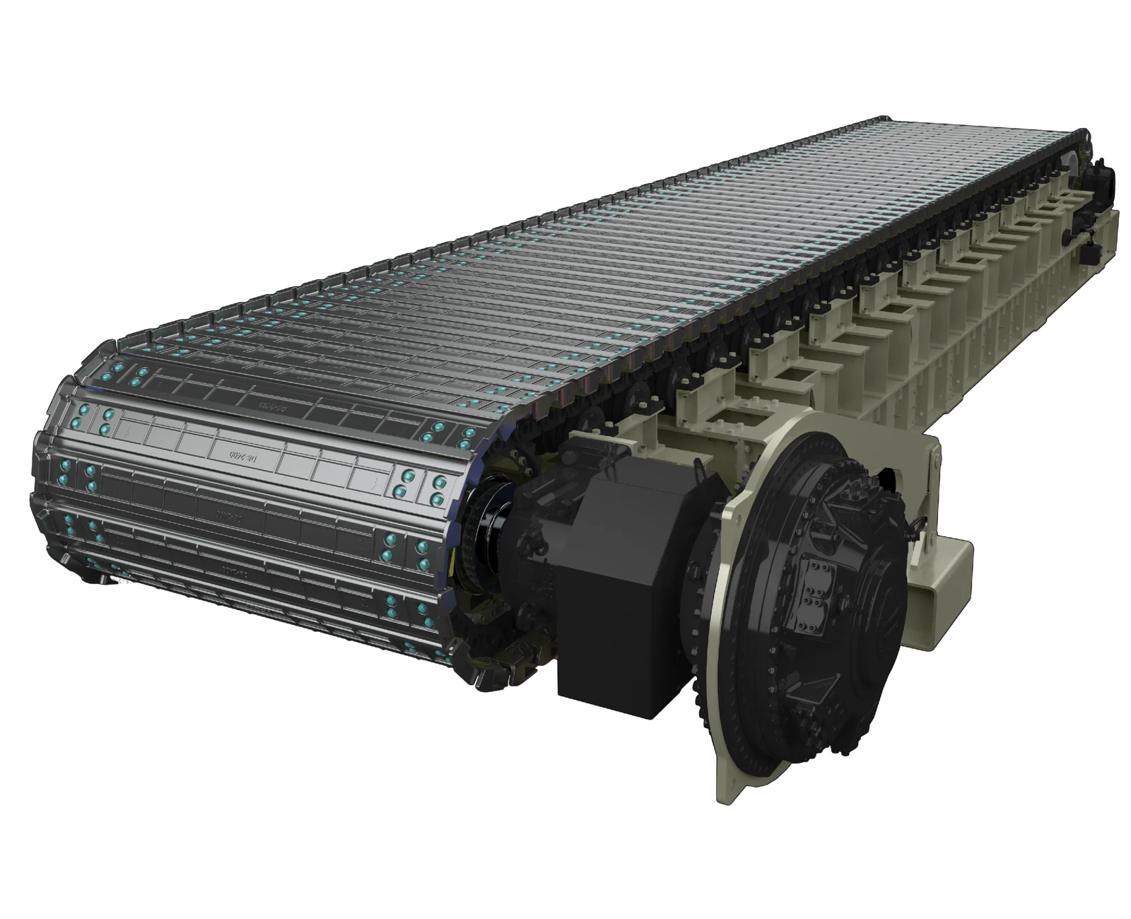
Metso apron feeder
Metso apron feeder showing pans, the chain path, safety rails and direct-drive location.
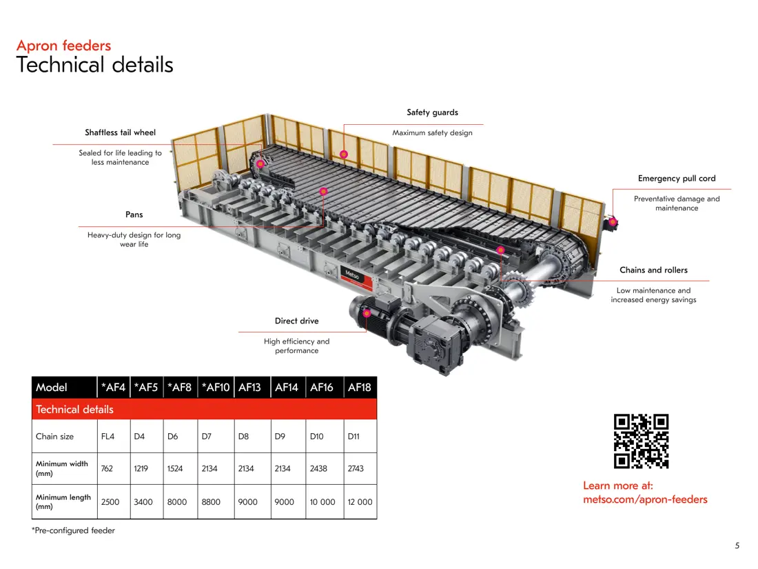
Metso apron feeder technical layout
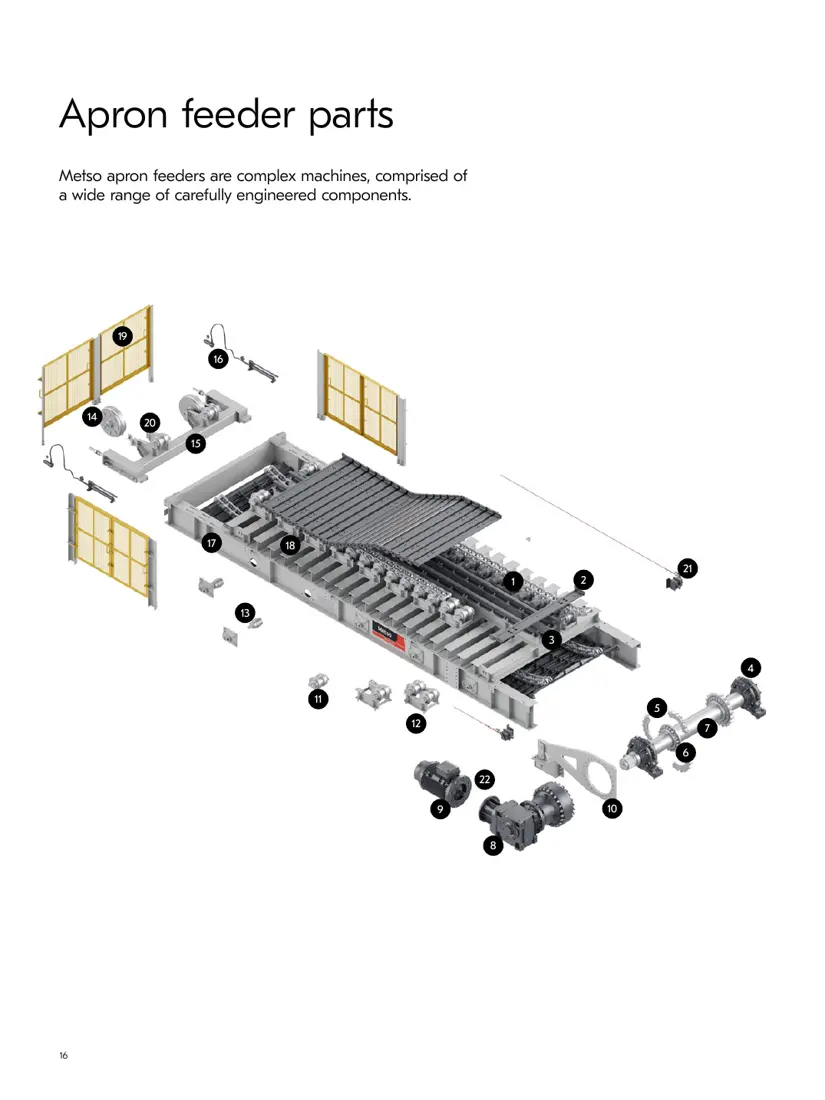
Metso apron feeder exploded view and component positions
Exploded view from Metso's 2026 brochure: 22 component positions identify chains, pans, impact beams, bearings, sprockets, head shafts, drives, rollers, tail wheels, tensioning and frame systems.
OEM Equipment Series

Confirm the AF Model and Dimensions Before Selecting Parts

Metso's current apron-feeder documentation lists standard and project configurations from AF4 to AF18. ANRANST focuses on pans and receiving-zone wear parts, chains and sprockets, rollers, head shafts and bearings, tensioning and structural repairs. The generic name apron feeder is not enough to identify an installed machine.

8AF series in the current brochure
914–3,353 mmListed standard width range
2,500–13,000+ mmListed standard length range
22Manufacturer exploded-view positions
Models and Key Dimensions

AF4–AF18 Standard Series

Only standard models, widths and lengths needed for part identification are listed. Confirm throughput, drive power, inclination and hopper loads from project documentation.

ModelKey dimensionsConfiguration
AF4Width 914–1,524 mm; length 2,500–7,900 mmPreconfigured series
AF5Width 1,219–2,134 mm; length 3,400–9,700 mmPreconfigured series
AF8Width 1,524–2,438 mm; length 8,000–12,200 mmPreconfigured series
AF10Width 2,134–3,048 mm; length 8,800–13,000 mmPreconfigured series
AF12Width 2,134–3,048 mm; length 8,800–13,000 mmStandard modular range
AF14Width 2,438–3,353 mm; length from 10,000 mmLength configured by width
AF16Width 2,438–3,353 mm; length from 10,000 mmHeavy-duty modular range
AF18Project-specific width and lengthCustom heavy-duty series
Model and dimension sources: Metso apron feeder product page and 2026 manufacturer brochure. The brochure identifies AF4, AF5, AF8 and AF10 as preconfigured series; AF18 dimensions are project-specific. Before manufacture, confirm the nameplate, serial number, drawing and revision, and physical interfaces.
Metso

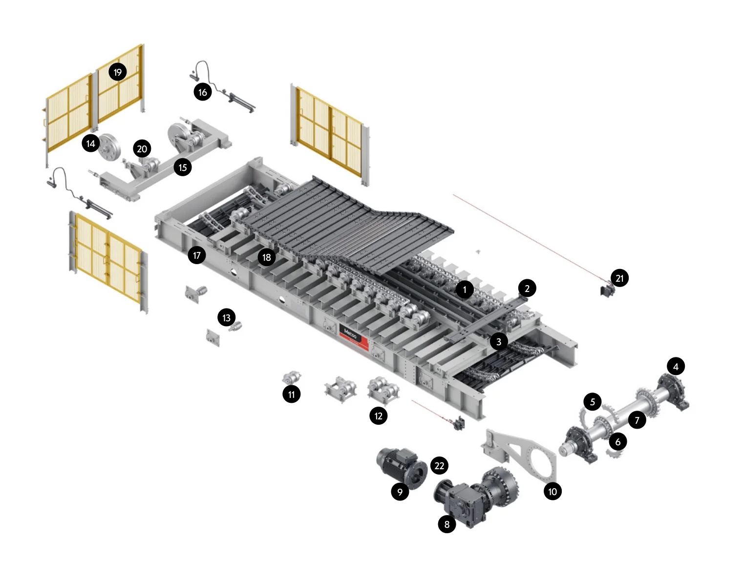
Component Location Diagram

The numbers on the diagram correspond one to one with the rows below.

Metso AF apron feeders – Component Location Diagram
No.ComponentLocationApplies to
1ChainSide chain beneath pans2025 handbook / motor and gearbox drive configuration
2Apron panWide carrying pan at top2025 handbook / motor and gearbox drive configuration
3Impact railLongitudinal impact rail beneath pans2025 handbook / motor and gearbox drive configuration
4BearingDetached bearing at right end of head shaft2025 handbook / motor and gearbox drive configuration
5SprocketSegmented sprocket on head-shaft assembly2025 handbook / motor and gearbox drive configuration
6HubHub at centre of sprocket2025 handbook / motor and gearbox drive configuration
7Head shaftTransverse shaft between sprockets2025 handbook / motor and gearbox drive configuration
8GearboxDetached gearbox at lower right2025 handbook / motor and gearbox drive configuration
9Drive motorDetached motor at lower left2025 handbook / motor and gearbox drive configuration
10Torque arm / linkageTorque arm connecting gearbox to main frame2025 handbook / motor and gearbox drive configuration
11Carry rollerDetached carrying roller beneath chain2025 handbook / motor and gearbox drive configuration
12Roller moduleModular frame carrying rollers2025 handbook / motor and gearbox drive configuration
13Return rollerLower return-chain support roller2025 handbook / motor and gearbox drive configuration
14Idler tail wheelDetached round idler tail wheel2025 handbook / motor and gearbox drive configuration
15Take-up frameSupport frame of tail take-up assembly2025 handbook / motor and gearbox drive configuration
16Take-up systemHydraulic and screw take-up equipment at tail2025 handbook / motor and gearbox drive configuration
17FrameMain load-bearing feeder frame2025 handbook / motor and gearbox drive configuration
18CrossbeamCrossbeam between frame sides2025 handbook / motor and gearbox drive configuration
19GuardDetached yellow side safety guard2025 handbook / motor and gearbox drive configuration
20Zero-speed switchZero-speed detection switch near tail wheel2025 handbook / motor and gearbox drive configuration
21Emergency pullcordEmergency pullcord and trip switch along feeder side2025 handbook / motor and gearbox drive configuration
22Lubrication systemCentralized lubrication equipment near drive assembly2025 handbook / motor and gearbox drive configuration
Wear parts

Pans and Receiving-Zone Wear Parts

Assess impact, sliding abrasion and deformation separately at the pans, inlet, sidewalls, discharge, impact supports and spillage zones, then select materials, heat treatment and replaceable designs.

Feeder Pans / Carrying Plates
01

Feeder Pans / Carrying Plates

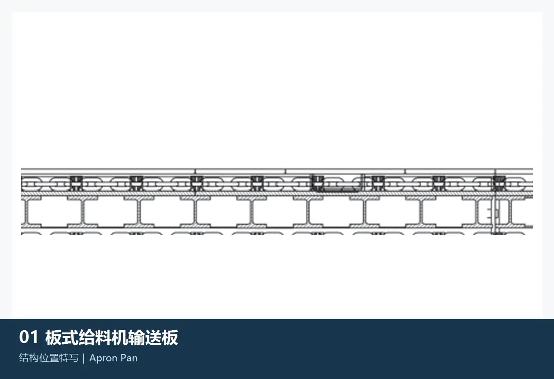
Pans / Flights

Pans directly withstand large-lump impact, compression and sliding wear. Metso's current brochure specifies cast high-manganese steel pans with bolted connections, lifting holes and wear indicators. Confirm profiles, hole positions and main/secondary pan combinations for the installation.

Side / Skirt Liners
02

Side / Skirt Liners

Side Liners / Skirt Liners

Installed along the material bed to limit side spillage and protect the hopper or walls. Distinguish large-lump impact zones, fine-material sliding abrasion and running clearance to the pans when selecting materials. The image illustrates the generic component category.

Tail-End Inlet Liners
03

Tail-End Inlet Liners

Tail / Inlet Liners

Located at the receiving and tail zones, these liners mainly face falling-material impact and wear from accumulated material. Check mounting profile, thickness, holes, overlaps and replacement access. The image illustrates the generic component category.

Head-End Discharge-Chute Liners
04

Head-End Discharge-Chute Liners

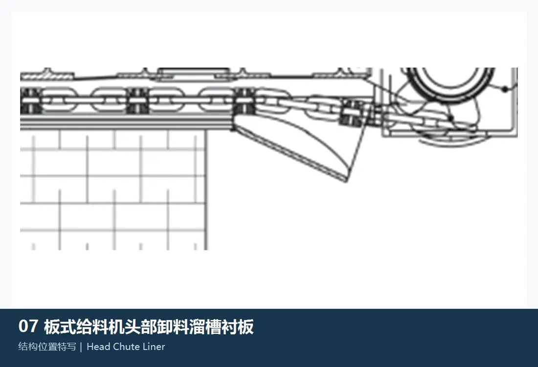
Head / Discharge Chute Liners

Located along the head-end discharge path and downstream chute connection, these liners face continuous scouring, local impact and fine-particle abrasion. Select materials and design by drop height, particle size, moisture and replacement interval. The image illustrates the generic component category.

Impact Beams / Plates
05

Impact Beams / Plates

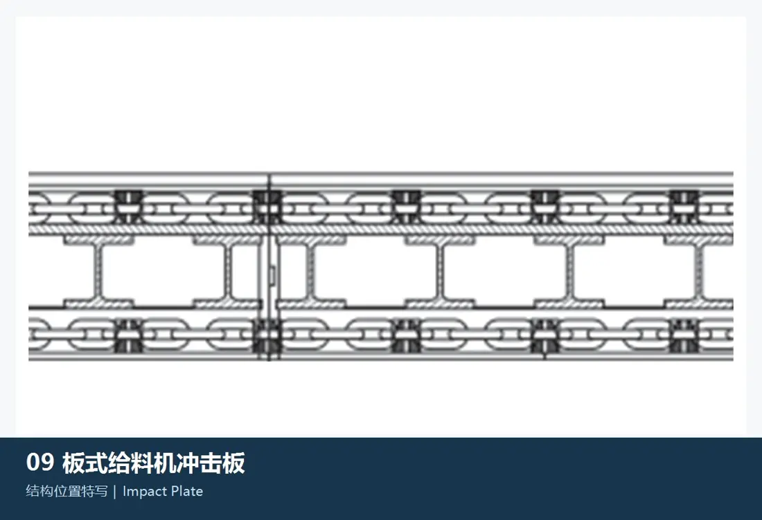
Impact Rails / Impact Plates

Installed below the heavy-duty receiving zone to support pans and reduce permanent impact deformation. Metso's current brochure specifies hardened-steel impact beams. Confirm actual width, beam count and interfaces before manufacture. The image illustrates the generic component category.

Spillage-Tray Liners
06

Spillage-Tray Liners

Drip Pan Liners

Located under the return run and frame to collect material falling through pan gaps and protect the frame. Fine-particle abrasion and cleaning access dominate selection; consider removability, buildup and corrosion. The image illustrates the generic component category.

Spare parts

Chain-Drive, Support and Structural Spares

Check chains, sprockets, rollers, head shafts, bearings, tensioning and drive as one aligned system. Structural repairs also require checks of frame straightness, roller elevations and chain centre distance.

Chains and Links
01

Chains and Links

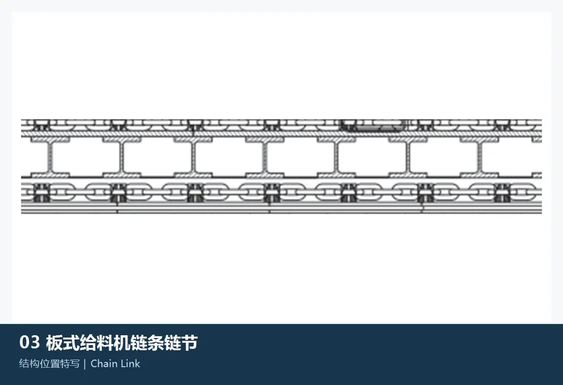
Chains / Chain Links

Metso's current brochure specifies tractor-type sealed and lubricated chains. Check chain specification, pitch, link design, connection method, left/right pairing and operating elongation.

View the general component guide →
Chain Pins and Bushings
02

Chain Pins and Bushings

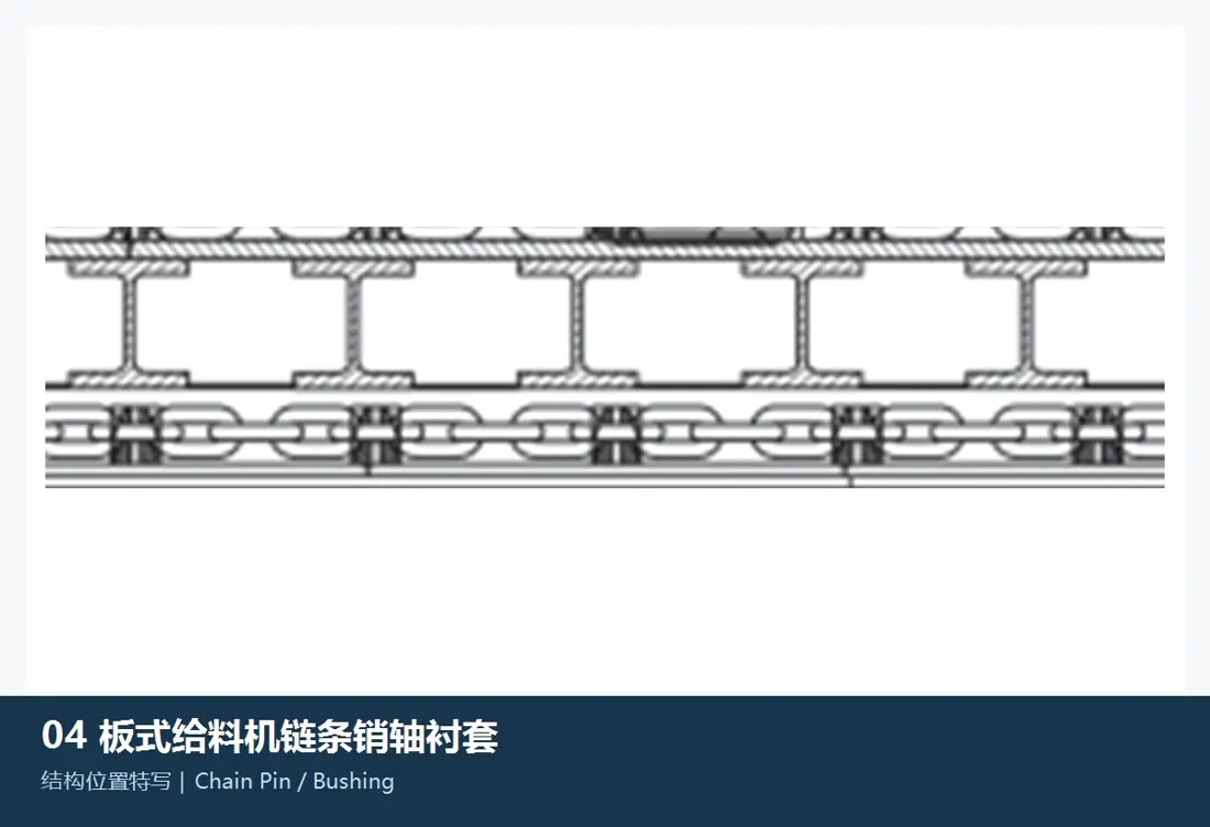
Chain Pins & Bushings

Pins and bushings form the main wear pair at chain articulations. Confirm them together by chain series, mating dimensions, material, heat treatment, surface hardness and lubrication condition.

View the general component guide →
Drive Sprockets and Hubs
03

Drive Sprockets and Hubs

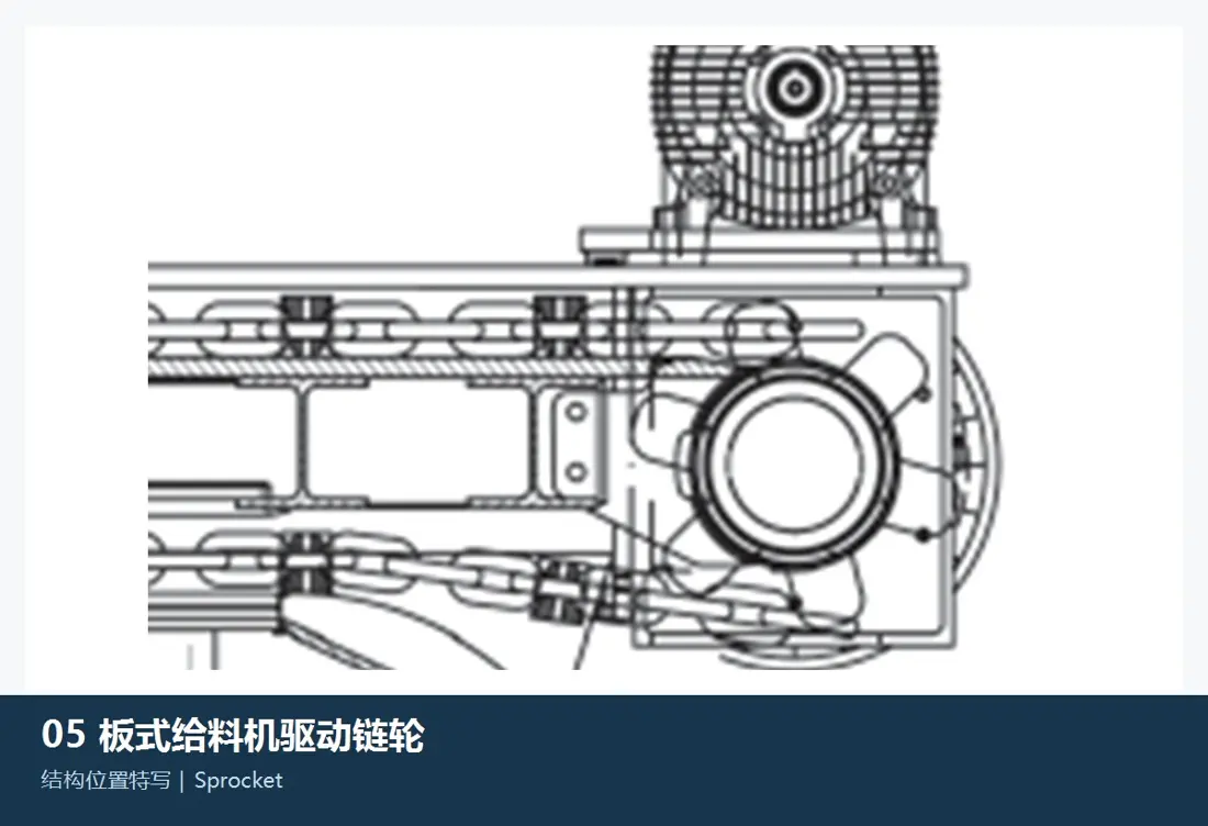
Drive Sprockets & Hubs

The brochure specifies hardened, reversible sprockets and separately machined hubs. Check tooth count and profile, keyways, hub fits and chain specification together.

View the general component guide →
Carry and Return Rollers
04

Carry and Return Rollers

Carry & Return Rollers

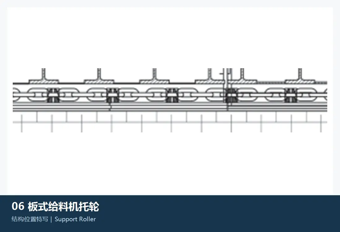
Carry rollers support the loaded run; return rollers support the returning chain and pans. Specify position, roller dimensions, shaft-end design, seals, lubrication and modular mounts in the enquiry.

View the general component guide →
Tail Wheels and Tensioning Systems
05

Tail Wheels and Tensioning Systems

Idler Tail Wheel & Take-up System

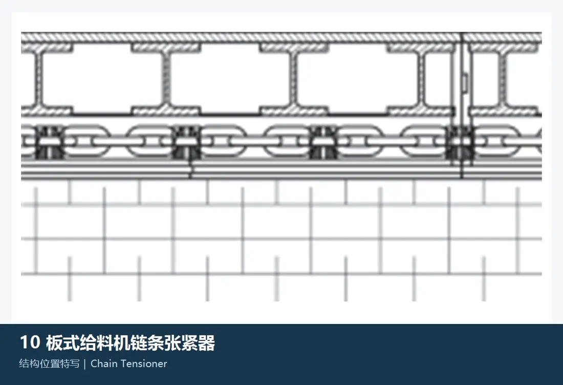
Metso's current brochure lists shaftless tail wheels, tensioning frames and hydraulic-cylinder or manual-screw tensioners. Confirm chain centre distance, stroke, mounting blocks and site adjustment method.

View the general component guide →
Head Shafts, Bearings and Split Housings
06

Head Shafts, Bearings and Split Housings

Head Shaft, Bearings & Split Housings

The exploded view identifies head shafts, sprockets, hubs and bearings separately. The brochure specifies a forged high-alloy head shaft, spherical roller bearings and split housings. Confirm journals, splines, keyways and bearing models before manufacture.

View the general component guide →
Gearboxes, Couplings and Motors
07

Gearboxes, Couplings and Motors

Reducer, Coupling & Motor

Manufacturer information lists planetary gearboxes, splined connections, motors and torque arms. ANRANST focuses on interface measurement, connecting and support parts, and project coordination. Confirm original drive units by nameplate and configuration.

Send details for technical confirmation →
Frames, Crossmembers and Roller Modules
08

Frames, Crossmembers and Roller Modules

Frame, Crossbeams & Roller Modules

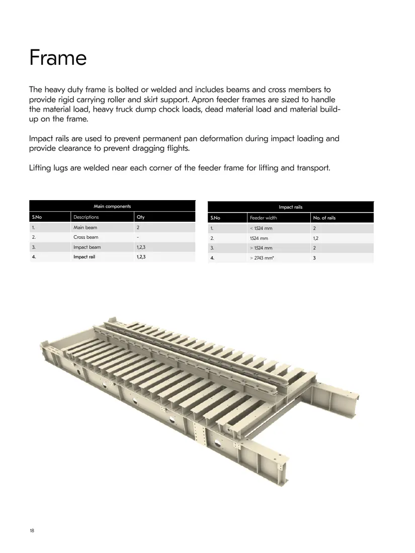
The heavy-duty frame comprises main beams, crossmembers, impact beams and roller modules. Repair or replacement requires checks of overall straightness, chain centrelines, roller elevations, welded construction and site lifting conditions.

Send details for technical confirmation →
FAQ

Frequently asked questions

What information is needed for a Metso apron-feeder spare-part enquiry?

Provide the AF model, nameplate or serial number, part or drawing, installed-part photographs, key dimensions, feeder width, chain specification and processed material.

Is an AF4 or AF10 model name enough to manufacture pans?

No. The model only narrows the range. Confirm feeder width and length, main/secondary pan combination, holes, chain interfaces, drawing and actual dimensions.

Can sprockets and head shafts be identified without a Metso model details?

The model, chain specification, assembly photographs and measurements can narrow the search. Before manufacture, confirm drawings, tooth profile, journals, keyways or splines and fit tolerances.

Send Your Metso AF Model, Drawing or Sample

Provide the nameplate, serial number, feeder width and length, chain specification, installed-part photographs, drawings, material and operating conditions. These support part identification, material assessment, production at certified foundries, quality control and finished-part delivery.

Equipment Brand and ModelDrawingDrawing or DimensionsCurrent MaterialPhotographs of Failed PartsTarget Service LifeOperating Conditions
Request a Quote

Or contact us directly: +86 156 3797 3199
zzx@anranst.com

Manufacturing Services in China

From Technical Assessment to Finished-Part Delivery

ANRANST provides customers worldwide with engineering assessment, production at certified foundries to the customer technical requirements, quality control and finished-part delivery for custom wear parts and industrial spares, with scope to support other custom industrial parts.

01

Drawing and Engineering Review

We review mating surfaces and interface dimensions and assess material, heat treatment and manufacturing feasibility.

02

Material and Heat-Treatment Specification

Material grades and heat-treatment processes are specified order by order, stated in the technical agreement and tracked through production.

03

Quality Control

Drawing confirmation, material and process control, production tracking, inspection and acceptance coordination.

04

Finished-Part Delivery

We coordinate manufacturing, quality confirmation, packaging and delivery of complete finished parts in a workable, closed-loop supply process.

Provide the existing model, drawings, drawing, materials or operating conditions so we can identify the appropriate technical review and supply route.

Submit an Enquiry