Metso Vertimill® VTM Models, Liners and Spares

Use VTM models and key dimensions to identify screw wear liners, end liners, wear caps, shaft liners, Orebed® magnetic liners, drive spares and maintenance tools. Drawing references, generations and dimensions guide manufacture in China, quality control and delivery.

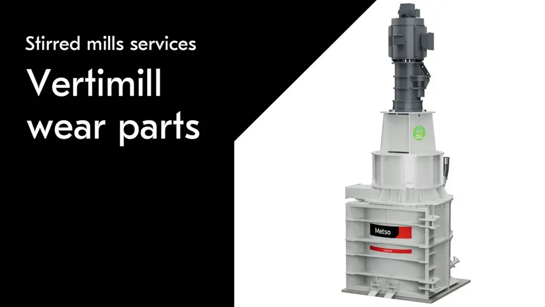
Metso Vertimill machine
Metso Vertimill® machine, showing the vertical arrangement, drive end, grinding chamber and maintenance space.
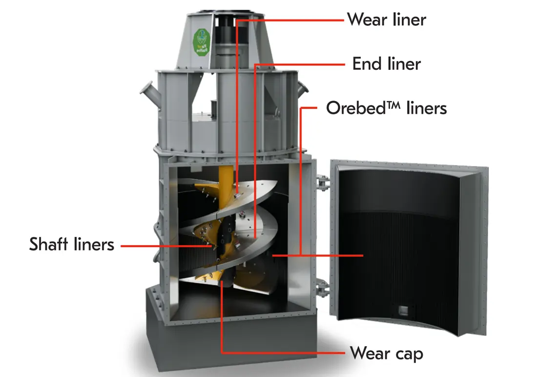
Metso Vertimill screw liners, shaft liners, wear cap and Orebed locations
Vertimill® chamber cutaway showing wear liners, end liners, shaft liners, wear caps and the Orebed® area.
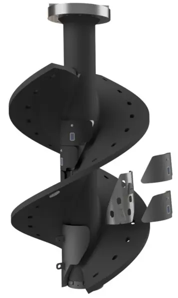
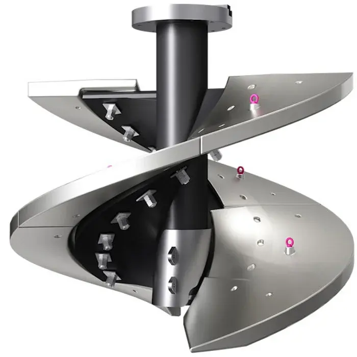
Metso Vertimill screw liner assembly
Vertimill® screw and segmented liner assembly, for checking wear and end liners, lifting points, hole patterns and adjoining interfaces.
OEM Equipment Series

Confirm the VTM Model and Liner Generation before the Model Details or Drawing

Vertimill® is Metso's gravity-induced vertical stirred mill range. Screw liner quantities, hole patterns, lifting points, rubber pads and model details differ across VTM, W/WB, C/LS and legacy VGX models. Only model and component relationships supported by manufacturer information are published here.

7 groupsModels with published overall dimensions
Multiple generationsInstallations covered by the manufacturer liner catalogue
2 typesScrew wear liners / end liners
Check each numberModel, generation, drawing and dimensions
Models and Key Dimensions

Published Standard Vertimill VTM Models

Only overall dimensions, installed power and empty weight needed for spare-part identification are listed. Model numbers denote horsepower classes and must not be read directly as kW. Confirm each project against the nameplate, data sheet and general arrangement.

Standard modelH × L × WMotor powerEmpty weight
VTM-650-WB12,270 × 3,250 × 3,860 mm485 kW / 650 hp82.6 t
VTM-800-WB13,460 × 3,560 × 4,060 mm597 kW / 800 hp100.4 t
VTM-1000-WB13,460 × 3,660 × 4,270 mm746 kW / 1,000 hp116.1 t
VTM-1250-WB13,460 × 4,090 × 4,520 mm932 kW / 1,250 hp125.4 t
VTM-1500-WB14,220 × 4,370 × 4,570 mm1,118 kW / 1,500 hp167.0 t
VTM-3000-WB17,590 × 6,820 × 6,880 mm2,237 kW / 3,000 hp343.0 t
VTM-4500-C18,600 × 6,820 × 6,880 mm3,355 kW / 4,500 hp367.079 t
Key dimensions follow the Vertimill technical data in Metso's Basics in Minerals Processing. Metso's current product page also lists VTM-7000. Confirm its project dimensions, power, interfaces and spares from the relevant project data sheet; do not apply VTM-4500-C data. View Metso Technical Information
Legacy Installation Identification

Recorded Legacy VTM Models and Suffixes

These models connect legacy nameplates and used-part records to the same Vertimill wear-part, spare-part, material and enquiry process. Complete suffixes, serial numbers, liner generations, drawing and drawings remain essential for manufacturing approval.

Installation group Recorded models Identification and part checks
Small and early VTM-WB models VTM-15-WB, VTM-20-WB, VTM-30-WB, VTM-100-WB, VTM-125-WB, VTM-250-WB, VTM-300-WB, VTM-500-WB Check nameplate, complete suffix, serial number, screw assembly and liner generation
Medium and large VTM-WB models VTM-650-WB, VTM-800-WB, VTM-1000-WB, VTM-1250-WB, VTM-1500-WB, VTM-2250-WB, VTM-3000-WB Check assembly revision, liner segmentation, drawing, interface dimensions and drive configuration
Legacy VTM-C, W and LS suffixes VTM-3750-C, VTM-4500-C; legacy W, LS and other naming variants Confirm the complete nameplate, installation records and drawing revision; do not assume direct interchangeability with WB installations
Current product series Vertimill 7000 Confirm dimensions, power, interfaces and spares against the project's manufacturer data sheet, drawing and drawings
Manufacturer Catalogue Numbers

Screw Wear Liner and End Liner Identification

Several liner generations may exist for one model. Use these numbers to match used parts, installation records and drawings to the correct generation. Before manufacture, confirm drawing revision, interfaces, quantity and measured dimensions.

Applicable model group Wear liner model details End liner model details
VTM-3000-WB / VTM-4500-C 03-525695 · ZX12002078 · ZX11853305 ZX11641731 · ZX12035288 · ZX11739360 · ZX11833209
VTM-2250-WB / VGX-3000 ZX11875643 ZX11875644
VTM-1500-WB / VGX-1850 03-156395 · ZX11812072 03-156390 · ZX11557494 · ZX11754067 · ZX11821859
VTM-1250-WB / VGX-1500 03-156375 · ZX11580931 · ZX11939436 · ZX11998733 03-156370 · ZX11460132 · ZX11841086 · ZX11998732
VTM-1000-WB / VTM-1250-W / VGX-1250 03-156345 · ZX11715689 03-156340 · ZX11715692 · ZX11803773
VTM-800-WB / VTM-900-W 03-156314 · ZX11574390 03-156313 · ZX11574395 · ZX11984828
VTM-650-WB / VTM-800-W 03-156335 · ZX11384786 03-156330 · ZX11384787 · ZX11878909 · ZX11984810
VTM-500-WB / VTM-600-W 03-156382 · ZX11937278 03-156381 · ZX11937217 · ZX11915417
VTM-400-WB / VTM-400-LS / VTM-500-W 03-005004 · MM1565336 03-156305 · MM1565428
VTM-250/300-WB / VTM-300/350-W / VTM-300-LS 03-156365 03-156360
VTM-150/200-WB / VTM-200/250-W / VTM-200/250-LS 03-056604 03-271600
VTM-125-WB / VTM-150-W / VTM-150-LS 03-200200 · ZX11888379 03-156320 · ZX11888297
VTM-75-WB / VTM-100-W / VTM-100-LS 03-056503 03-056808
VTM-40/60-WB / VTM-50/75-W / VTM-50/75-LS 03-056901 03-214100
VTM-20-WB / VTM-30-LS 03-207300 03-207200
VTM-15-WB / VTM-20-W / VTM-20-LS 03-147202 03-147302

Numbers follow the Metso Vertimill® wear parts catalogue, retaining legacy W/WB, C/LS and VGX installation relationships. ANRANST is an independent wear-parts engineering team; manufacturer authorization is not implied. Enquiries require model, serial number, liner generation, drawings and used parts to be checked together.

Metso

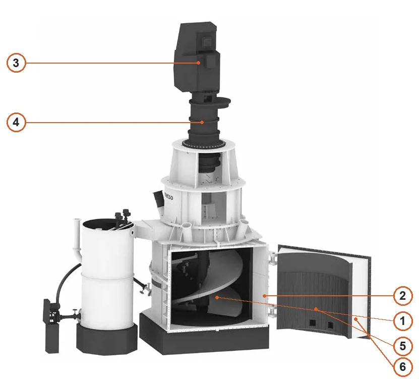
Component Location Diagram

The numbers on the diagram correspond one to one with the rows below.

Metso Vertimill® VTM – Component Location Diagram
No.ComponentLocationApplies to
1Agitating screwScrew inside open grinding chamberVertimill handbook section configuration; exact model not specified
2Grinding chamber shellRight-hand shell surrounding grinding screwVertimill handbook section configuration; exact model not specified
3Drive motorDrive motor at topVertimill handbook section configuration; exact model not specified
4GearboxGear reducer below motorVertimill handbook section configuration; exact model not specified
5Magnetic liningLining on open access door at rightVertimill handbook section configuration; exact model not specified
6Access doorOpen chamber access-door frame at rightVertimill handbook section configuration; exact model not specified
Wear Parts

Screw, Shaft and Grinding-Chamber Wear Systems

Loads and wear differ by position. Screw liners withstand abrasion and stirring loads; shaft components isolate erosive flow; Orebed® uses magnetic material to form a protective layer. Determine materials by position, drawing and operating conditions.

Vertimill screw wear liner
01

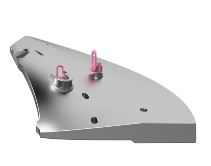
Screw Wear Liners

Screw Wear Liners

Mounted on the working face of the screw flights to protect the screw body and maintain its profile. Check model, generation, quantity per mill, holes, thickness, lifting points and wear direction. The cast wear-resistant alloy must be checked against the drawing.
Vertimill end liner
02

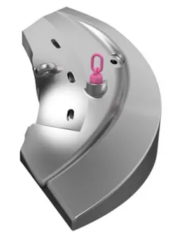
End Liners

End Liners

Located at the lower end of the screw, usually as two pieces per mill. This area encounters slurry erosion, abrasion and local impact. Check inner and outer profiles, paired fit, generation and lifting holes.

Vertimill wear cap
03

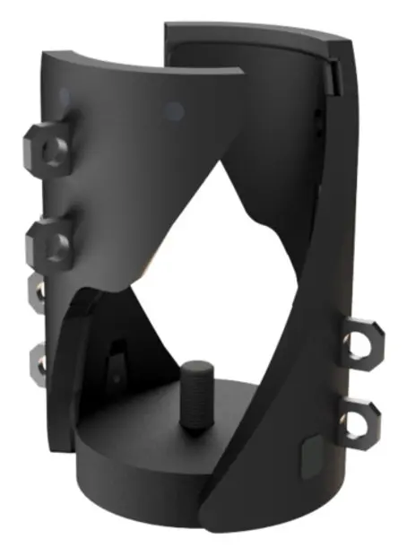
Shaft-End Wear Caps

Wear Cap Kits

Protect the bottom of the screw shaft. Cast iron, rubber or rubber/polyurethane designs vary by model and generation. Appearance alone is insufficient; check the original model details, fastening holes and shaft-end interface.

Vertimill shaft liner location
04

Shaft Liners and Adapter Plates

Shaft Liners & Adapter Plates

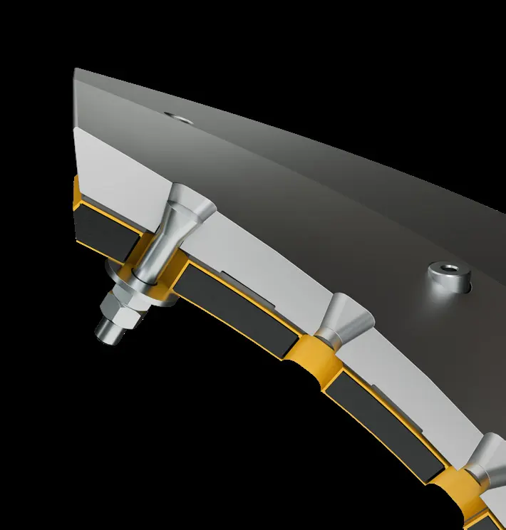
Shaft liners protect the screw shaft from slurry and abrasive particles; adapter plates and wedges form the mounting interface. The manufacturer catalogue specifies rubber shaft liners and mild-steel adapter plates. Check section quantities, weld positions and clamping relationships.

Vertimill liner fasteners and rubber pads
05

Fasteners, Special Washers and Rubber Pads

Attachment Hardware & Rubber Pads

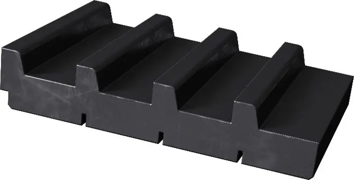
Includes oval-head bolts, special washers, nuts and rubber pads used with specific polyurea-lined shaft configurations. Check threads, lengths, quantities per liner, preloading method and liner generation.

Vertimill Orebed magnetic liner unit
06

Orebed® Magnetic Liners

Orebed® Magnetic Liners

Used on the mill wall and door, with permanent ceramic magnets embedded in wear-resistant rubber. A protective layer forms only when the media or slurry contains enough ferromagnetic material. Designs differ between VTM-1500 and smaller models and VTM-2250 and larger models.

Shaft protection model details

Wear Caps, Shaft Liners and Adapter Plates

Shaft protection parts vary by model and generation. Rubber, rubber/polyurethane and cast-iron versions must not be mixed. The following are identification numbers from the manufacturer catalogue.

Applicable model Component Original model details
VTM-3000-WB / VTM-4500-C Wear Cap Gen 1: cast iron / Gen 2: rubber ZX11736479 / ZX11897530
VTM-2250-WB / VGX-3000 Wear Cap Gen 1: cast iron AX02-100185735
VTM-1500-WB / VGX-1850 Wear Cap Gen 1/2/3 ZX11750007 / ZX11841891 / ZX11968277
VTM-1500-WB / VGX-1850 Shaft Liner Kit / Adapter Plate ZX11943843 / ZX11816433
VTM-1000/1250-WB / VTM-1250-W / VGX-1250/1500 Wear Cap Gen 1/2/3 ZX11721209 / ZX11881671 / ZX11998734
Same as above Shaft Liner / Adapter Plate ZX11962931 / ZX11853090
VTM-800-WB / VTM-900-W Wear Cap Gen 1/2 ZX11833426 / ZX11959231
VTM-650-WB / VTM-800-W Wear Cap Gen 1: cast iron ZX11769932
VTM-500-WB / VTM-600-W Wear Cap Gen 1: rubber ZX11896212
VTM-400-WB / VTM-400-LS / VTM-500-W Wear Cap Gen 1: cast iron ZX11848309
Orebed® Identification

Magnetic Liner Types, Dimensions and Model Details or Drawing

All-rubber units are used for VTM-1500 and smaller models; steel-capped units for VTM-2250 and larger models; high-temperature steel-capped units for lime slaking. Applicability still depends on material magnetism and the original construction.

Type Nominal width × length Original model details
All rubber 6.25 × 10 / 7.5 / 5 / 2.5 in 02-804289 / 02-804713 / 02-804714 / 02-804715
All rubber 3.125 × 10 / 7.5 / 5 / 2.5 in 02-804716 / 02-804717 / 02-804718 / 02-804719
Steel capped 6.25 × 10 / 7.5 / 5 / 2.5 in 02-800306 / 02-801247 / 02-801519 / 02-802042
Steel capped 3.125 × 10 / 7.5 / 5 / 2.5 in 02-801246 / 02-801248 / 02-801520 / 02-802043
High-temperature steel capped 6.25 × 10 / 7.5 / 5 / 2.5 in SK-02-810826 / ZX11298009 / SK-02-810827 / ZX11771421
Spare Parts

Drive, Support and Screw Structural Spares

The fixed-speed motor, planetary gearbox, spherical roller bearings and suspended screw form the Vertimill drive and support system. Check spare parts together against the specific model, shaft arrangement, interfaces, lubrication and mounting datums.

Vertimill top-mounted motor and planetary gearbox location
01

Motor and Planetary Gearbox Interface Parts

Motor & Planetary Gearbox Interfaces

Check VTM model, power, output shaft, flanges, connectors, rotation direction, lubrication connections and installation elevation. Identify internal gearbox parts from the nameplate, assembly number and manufacturer drawings; general tower-mill data is not a substitute.

Open General Drive Identification →
Vertimill upper bearing and suspended shaft arrangement
02

Spherical Roller Bearings and Supports

Spherical Roller Bearings & Supports

Support the suspended screw shaft. Check the complete bearing designation and suffix, clearance, fits, housing, seals, lubrication and fixed/floating-end arrangement. Do not infer specifications from appearance.

Open General Bearing and Support Identification →
Vertimill screw shaft and flight structure
03

Screw Shaft and Screw Body

Screw Shaft & Screw Body

These are large structural spares, distinct from screw liners. Check overall length, journals, flanges, screw geometry, liner holes, welding and nondestructive testing. Identify shaft protection liners separately from the shaft itself.

Open the General Shaft Structure Page →
Confirmed Project Model Details or Drawing

VTM-3000-WB Project Assemblies and Drawings

This table applies only to the archived VTM-3000-WB wet vertical stirred mill project revision. Project assembly and general drawing differ in identification level from individual wear liner and end liner numbers in the public catalogue. Recheck the complete nameplate, serial number, drawing revision and actual interfaces; do not extrapolate to other VTM-3000-WB installations.

Confirmed component Project model details Drawing number Quantity per mill / recorded weight
Stirring screw assembly with vulcanized lining 05-066939 05-066939-01 1 piece / 25,041 kg
Screw wear liner assembly 05-066938 05-066938-01 1 set / 34,112 kg
Gearbox with coupling ZX11205715 10149257-DWK 1 piece / 40,364 kg
Motor with coupling ZX11205718 10149259-DWK 1 piece / 15,700 kg
Classification tank assembly ZX11211977 10143498-DWK 1 piece / 8,714 kg

Identification boundary: 05-066938 is this project's screw wear liner assembly number. It is not an individual wear liner number listed by generation in the public catalogue. Cross-check both with drawings, quantities, interfaces and installation revision.

Special Tooling

Liner Lifting and Screw Maintenance Systems

Only special tools explicitly listed in Metso Vertimill documentation are shown, with applicable models and component numbers. Select tooling by liner generation, working load and the specific maintenance task.

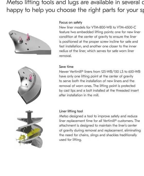
Metso Manufacturer InformationMetso Vertimill liner lifting tools and lugs

Liner Lifting Tools and Lugs

Install new liners and remove worn liners while maintaining the designed center of gravity and lifting angle. Tool numbers differ by VTM model, wear or end liner, and generation.

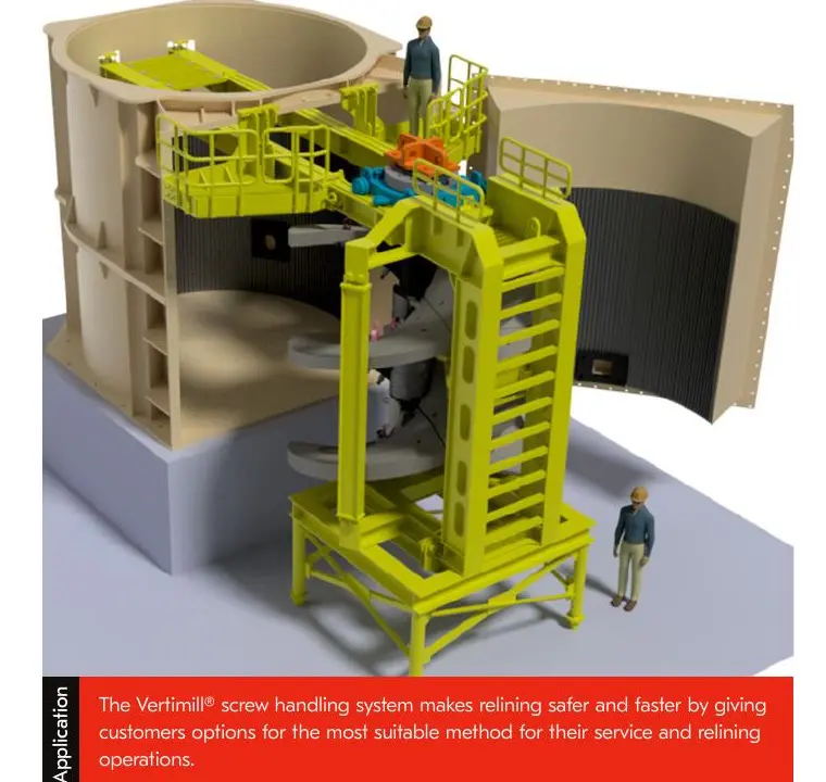
Metso Manufacturer InformationMetso Vertimill screw handling system

Screw Handling System

Includes service platforms, beam assemblies, support bases, lifting lugs, transport trolleys and screw jacking components. It supports, rotates and transports the screw shaft and liner assembly in front of the mill or in the maintenance area.

FAQ

Frequently asked questions

What is needed to quote Vertimill screw liners?

Provide the complete VTM model, serial number, wear liner or end liner position, current model details, liner generation, drawings, used-part photographs and key dimensions.

Can different liner generations for one model be interchanged directly?

The model alone is insufficient. Manufacturer information lists multiple liner generations, lifting points and mounting parts for one model. Recheck drawing, interfaces, generation and dimensions.

Is Orebed® suitable for every Vertimill application?

No. It relies on magnetic media or ferromagnetic material in the slurry to form a protective layer. Check material magnetism, temperature, mill model and original construction.

Submit Your Vertimill VTM Model, Liner Number or Drawings

Provide the complete model, serial number, wear liner or end liner position, current model details, liner generation, drawings, used-part photographs, material and operating conditions. We use these to identify the part, organize production at certified foundries, coordinate quality control and deliver the finished item.

Equipment Brand and ModelDrawingDrawing or DimensionsCurrent MaterialPhotographs of Failed PartsTarget Service LifeOperating Conditions
Request a Quote

Or contact us directly: +86 156 3797 3199
zzx@anranst.com

Manufacturing Services in China

From Technical Assessment to Finished-Part Delivery

ANRANST provides customers worldwide with engineering assessment, production at certified foundries to the customer technical requirements, quality control and finished-part delivery for custom wear parts and industrial spares, with scope to support other custom industrial parts.

01

Drawing and Engineering Review

We review mating surfaces and interface dimensions and assess material, heat treatment and manufacturing feasibility.

02

Material and Heat-Treatment Specification

Material grades and heat-treatment processes are specified order by order, stated in the technical agreement and tracked through production.

03

Quality Control

Drawing confirmation, material and process control, production tracking, inspection and acceptance coordination.

04

Finished-Part Delivery

We coordinate manufacturing, quality confirmation, packaging and delivery of complete finished parts in a workable, closed-loop supply process.

Provide the existing model, drawings, drawing, materials or operating conditions so we can identify the appropriate technical review and supply route.

Submit an Enquiry