
HIGmill Drive spares
Gearbox and Drive Components
Gearbox and Drive Components
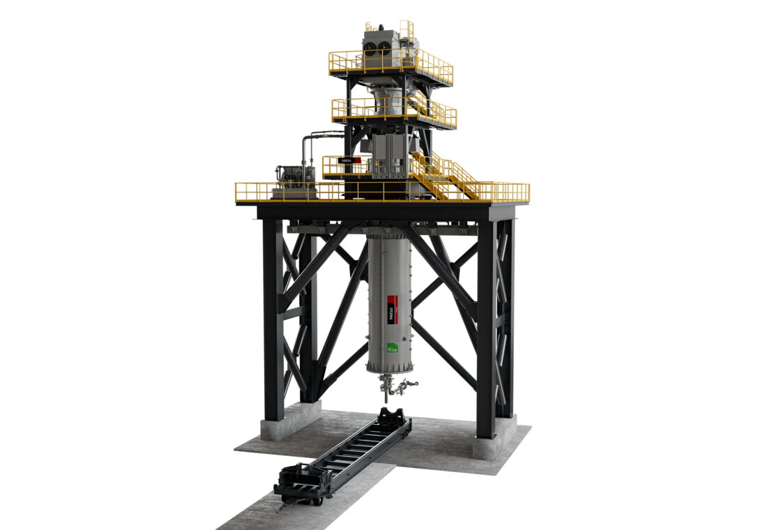
The HIGmill top drive transmits motor output to the vertical main shaft. This page covers identification, materials and supply to drawings for gears, pinion shafts, couplings, sleeves, connecting parts and their assembly interfaces.
Equipment Metso / Swiss Tower Mills HIGmill
Installation Position Mill top drive and main shaft input
Main Loads Continuous torque, start/stop impact, contact fatigue and bending fatigue
Identification requirements Gearbox nameplate, model, tooth profile, drawing and assembly drawing
Part scopeIndividual Part Gears, pinion shafts, sleeves and connecting parts Assembly configuration Coupling, drive assembly or complete gearbox Key parameters Tooth profile, accuracy, centre distance, fits and torque Quality priorities Materials, heat treatment, tooth inspection and contact patterns
Separate quotations for gears, shafts, sleeves and assemblies
A complete gearbox and individual internal drive parts have different supply scopes. Request a complete gearbox using existing records, or submit individual drawings for gears, pinions, pinion shafts, sleeves, couplings or connecting parts.
Gear spares require checks of module, tooth count, pressure angle, helix angle, profile shift, accuracy class, centre distance, surface hardening, fits and inspection standards. The equipment name alone is insufficient to identify a part.
Spare part categories
Identify individual drive components separately
Maintain a separate identifier, drawing and acceptance record for each drive component.
Gears and Pinion Shafts
Check tooth data, bore or shaft sections, surface hardness, root strength, tooth modifications and accuracy class.
Couplings and Connecting Parts
Check torque, bore diameter, keyways, flange hole pattern, flexible elements, dynamic balance and installation space.
Shaft Sleeves and Locking Parts
Check fit tolerances, surface roughness, locking method, assembly and removal requirements, and anti-seizure measures.
Materials and Processes
Confirm materials, heat treatment and tooth surface properties together
Select the grade in conjunction with the original drawing, loads and heat treatment capability.
Carburized / Quenched and Tempered Gear Alloy Steel Candidate materials for gears and pinion shafts, selected for contact fatigue, bending strength, core toughness, effective case depth and dimensional stability. Chromium–Molybdenum Alloy Steel Shaft Parts A candidate material route for shafts, sleeves and high-strength connecting parts. Assess section geometry, hardenability, fatigue and nondestructive inspection requirements.
Models and drawing
Check drive configuration against power rating and gearbox nameplate
The HIGmill model identifies the equipment range, but does not directly identify internal gear model details.
| HIGmill Model | Key identification details |
|---|---|
| HIG3500/23000 | 3,500 kW drive class; check gearbox manufacturer, ratio and assembly version |
| HIG500/4000 | 500 kW drive class; check site configuration, ratio and main shaft interface |
| HIG25 / HIG5 | Pilot and test drives; parts cannot be inferred from industrial units |
| Other industrial HIGmill models | Provide power, speed, gearbox brand and model, and existing parts |
Confirm third-party gear drawing against traceable tooth data, materials, heat treatment, accuracy and the applicable gearbox model.
RFQ information
Gear and drive component identification information
Dimensional surveys must include the matching gear, centre distance and failure analysis, as well as the individual part geometry.
Equipment and gearbox
HIGmill model, gearbox manufacturer, model and serial number.
Supply scope
Individual gear, matched gear set, shaft part, coupling or assembly.
Tooth data and dimensions
Module, tooth count, pressure angle, helix angle, centre distance and bore/shaft interfaces.
Materials and heat treatment
Grade, hardening method, hardness, effective case depth and core properties.
Accuracy and inspection
Gear accuracy, runout, tooth profile and lead, contact patterns and nondestructive inspection.
Part references and failure
OEM references, samples, drawings and photographs of pitting, broken teeth or abnormal wear.
Related Equipment and Parts
Equipment, main shaft and drive materials
Check drive components together with installed power, gearbox and main shaft interfaces.