
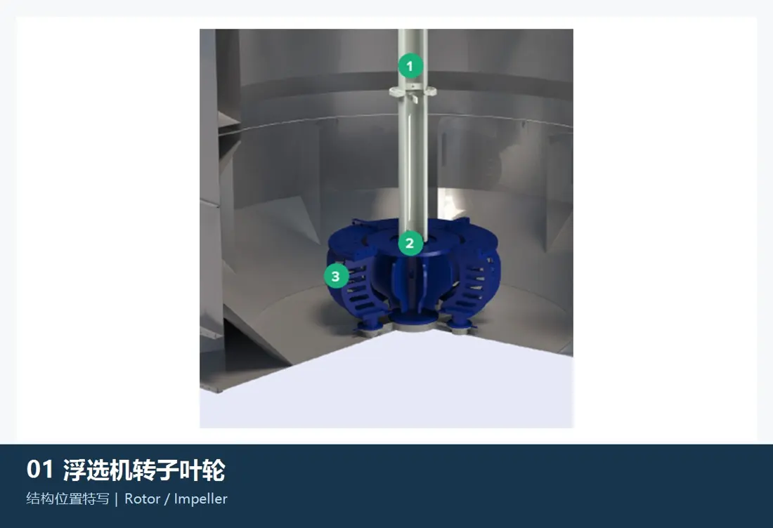
01
Rotor / Impeller
Rotor / Impeller
Suspends slurry, disperses air and creates circulation. Blade edges, passages and coverings face combined erosion, abrasion and chemical exposure.
View General Components and Suitable Materials →Identify installed Metso flotation models and source FloatForce mixing-mechanism wear parts, tank protection, level-control components and drive spares.
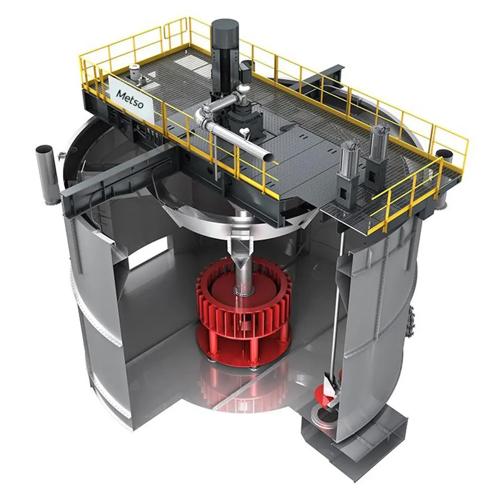
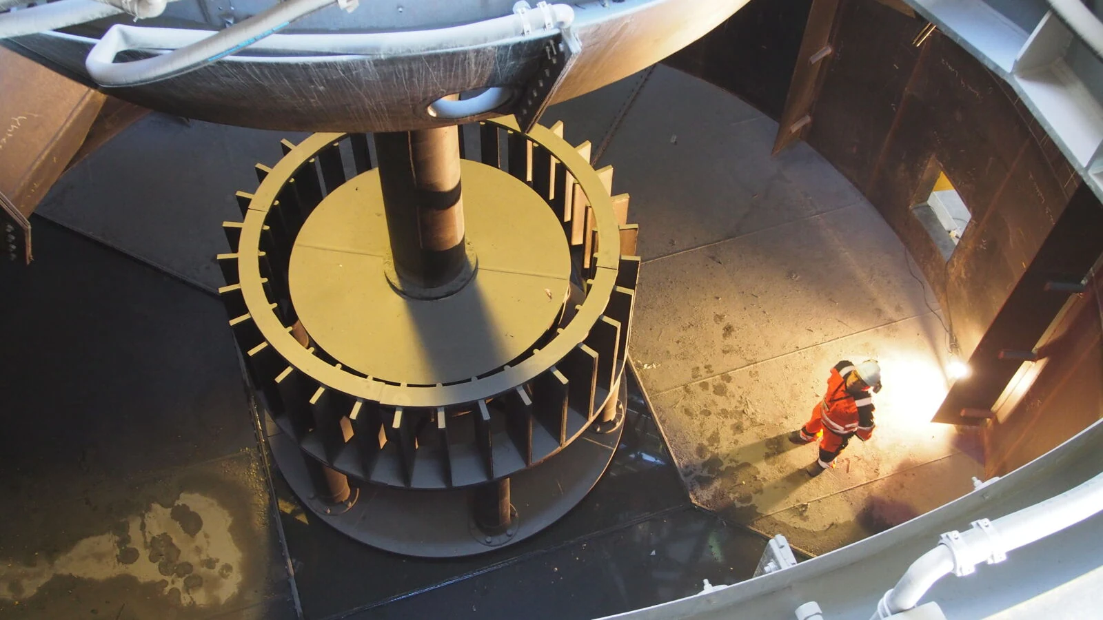
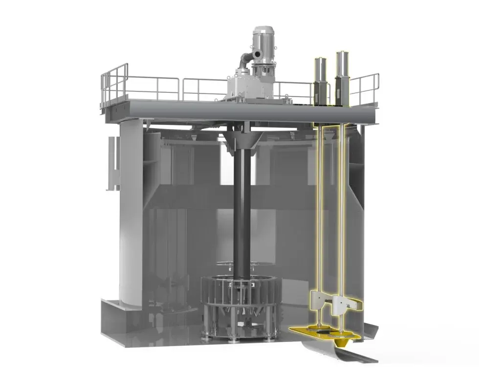
The label “flotation machine” alone is insufficient for matching parts. Begin with the series, effective volume, mixing-mechanism version and drawing revision, then review wear parts, drives, controls and materials.
Tank design, mixing mechanisms, level controls and spare-part interfaces differ between series. Establish the series before requesting a quotation.
| Equipment Series | Core Scope | Key Spare-Part Identification Areas |
|---|---|---|
| TankCell | 5–630 m³; e5–e630 | FloatForce/FloatForce+, bottom wear parts, drive shafts, Dart Valve and tank protection |
| Conventional OK Cell | 0.5–38 m³ | Mixing mechanisms, shafts, tank linings, air-flow and level-control spares |
| Concorde Cell | Flotation equipment for fine and complex ores | Jet/aeration systems, tank internals, valves and wear protection |
| ColumnCell | Flotation column series | Feed, bubble generation, wash-water, discharge and tank-protection parts |
| SkimAir | Flash flotation in grinding circuits | Mixing mechanisms, feed/discharge, tank wear areas and controls |
| RCS | Historical and operating mechanical-agitation series | Rotors and stators, shafts, drives, tank linings and level controls |
The table lists the effective volume, drive type and standard installed power needed for spare-part identification.
| Standard Model | Effective Volume | Drive Type | Standard Installed Power |
|---|---|---|---|
| TankCell e5 | 5 m³ | V-belt drive | 11 kW |
| TankCell e10 | 10 m³ | V-belt drive | 22 kW |
| TankCell e20 | 20 m³ | V-belt drive | 37 kW |
| TankCell e30 | 30 m³ | V-belt drive | 45 kW |
| TankCell e50 | 50 m³ | V-belt drive | 55 kW |
| TankCell e70 | 70 m³ | V-belt drive | 75 kW |
| TankCell e100 | 100 m³ | V-belt / gear drive | 110 kW |
| TankCell e130 | 130 m³ | V-belt / gear drive | 132 kW |
| TankCell e160 | 160 m³ | Gear drive | 160 kW |
| TankCell e200 | 200 m³ | Gear drive | 185 kW |
| TankCell e300 | 300 m³ | Gear drive | 250 kW |
| TankCell e500 | 500 m³ | Gear drive | 400 kW |
| TankCell e630 | 630 m³ | Gear drive | 500 kW |
The numbers on the diagram correspond one to one with the rows below.
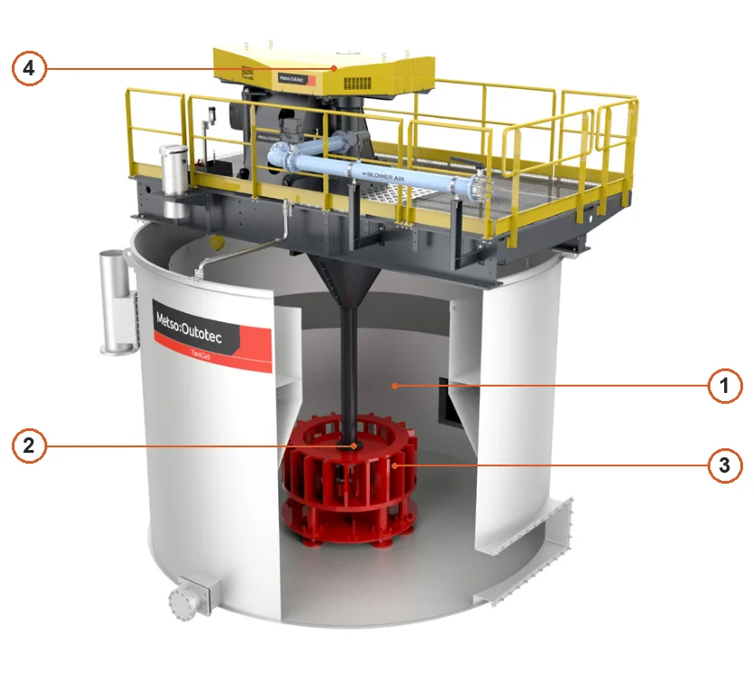
| No. | Component | Location | Applies to |
|---|---|---|---|
| 1 | Flotation tank | Tank shell in upper-right unit | TankCell |
| 2 | Rotor | Central rotor inside cutaway window | TankCell FloatForce configuration |
| 3 | Stator | Stator surrounding rotor | TankCell FloatForce configuration |
| 4 | Drive motor | Drive motor above flotation cell | TankCell |
Operating conditions, candidate materials and general component links are organised by wear location. The equipment model, mixing-mechanism version and drawings determine the specific design.
Rotor / Impeller
Suspends slurry, disperses air and creates circulation. Blade edges, passages and coverings face combined erosion, abrasion and chemical exposure.
View General Components and Suitable Materials →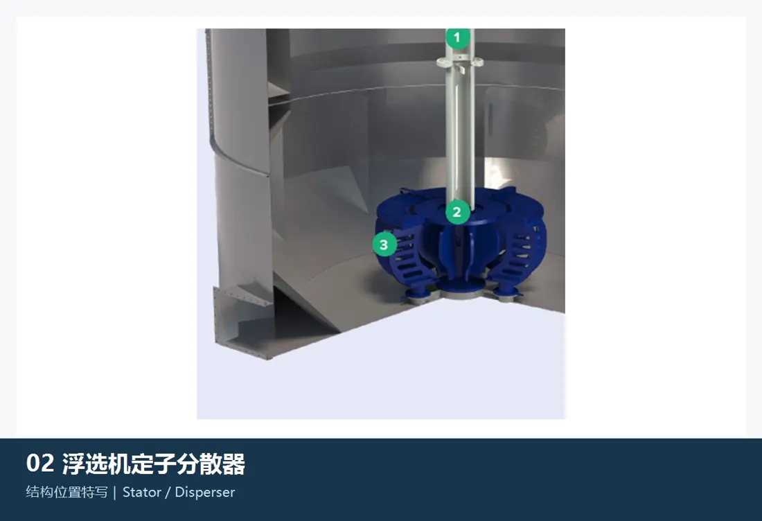
Stator / Disperser
Directs slurry flow and stabilises bubble dispersion. Blade leading edges, the inner ring and base connections are key erosion and fatigue areas to inspect.
View General Components and Suitable Materials →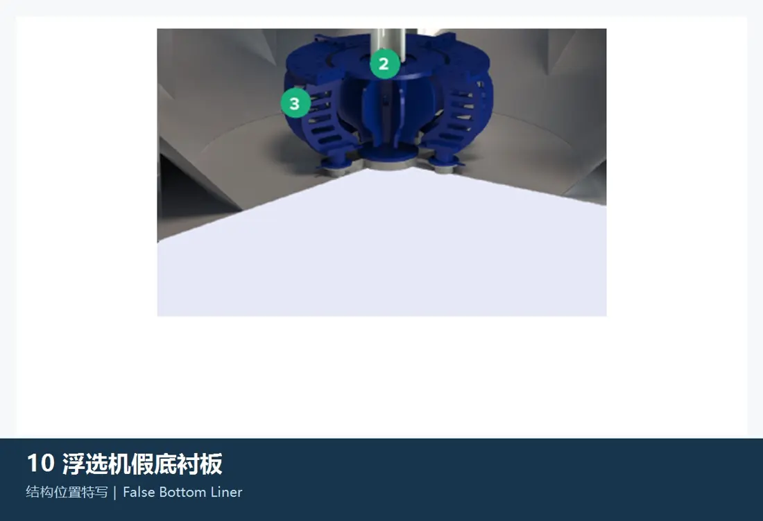
Tank-bottom Wear Parts
Protect the area beneath the mixing mechanism and highly agitated bottom zones. Check hole patterns, segmentation, thickness, fastening and clearance to the stator base.
View General Components and Suitable Materials →
Protective Tank Liners
Protect tank walls, bottoms and high-velocity areas against wear and corrosion. Slurry chemistry, temperature, solids concentration and failure mode determine material selection together.
View General Components and Suitable Materials →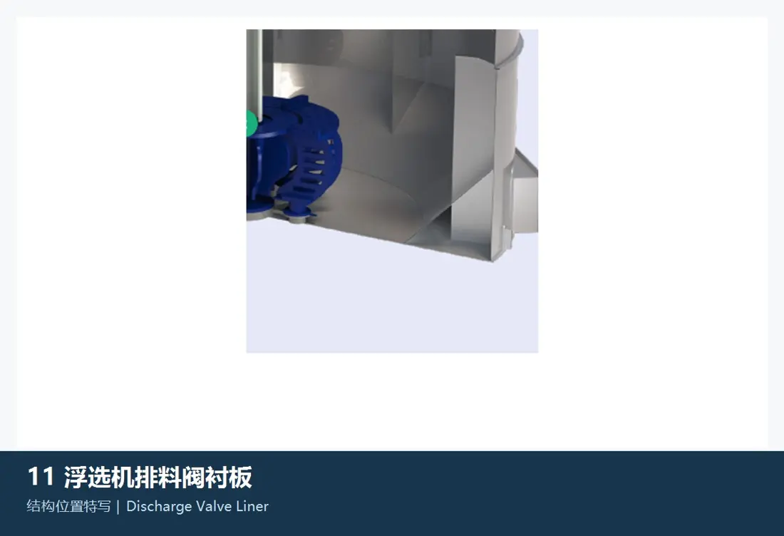
Dart Valve Wear Parts
Level-control valve plugs, seats and flow-path parts face throttling erosion and frequent movement. Verify stroke, seals, actuator and control configuration together.
View General Components and Suitable Materials →Identify drive and control parts separately, checking interface dimensions, accuracy, configuration version, seal type and installed equipment scope.
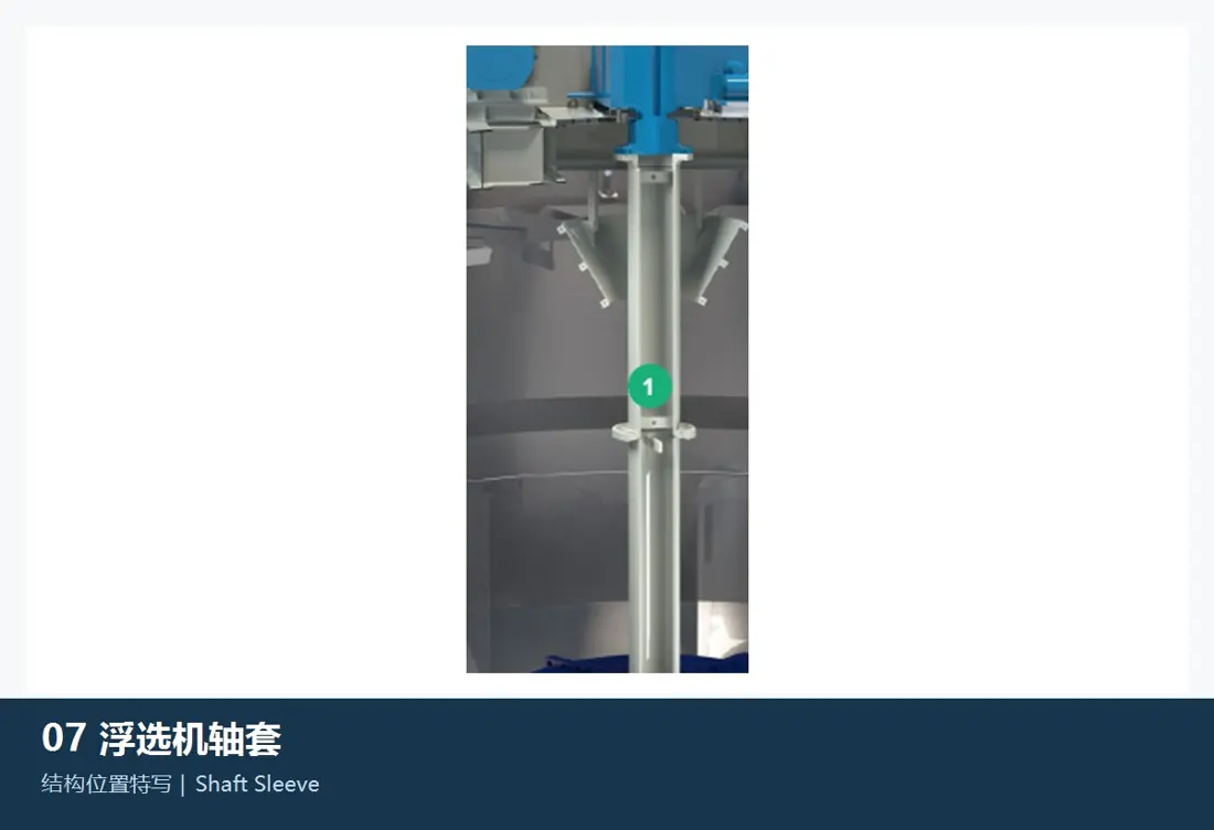
Drive, Main Shaft & Sleeve
Includes motors, belt or gear drives, main shafts, connections and sleeves. Check power, speed, shaft diameters, fits, keyways and mixing-mechanism interfaces.
View the General Shaft Component Page →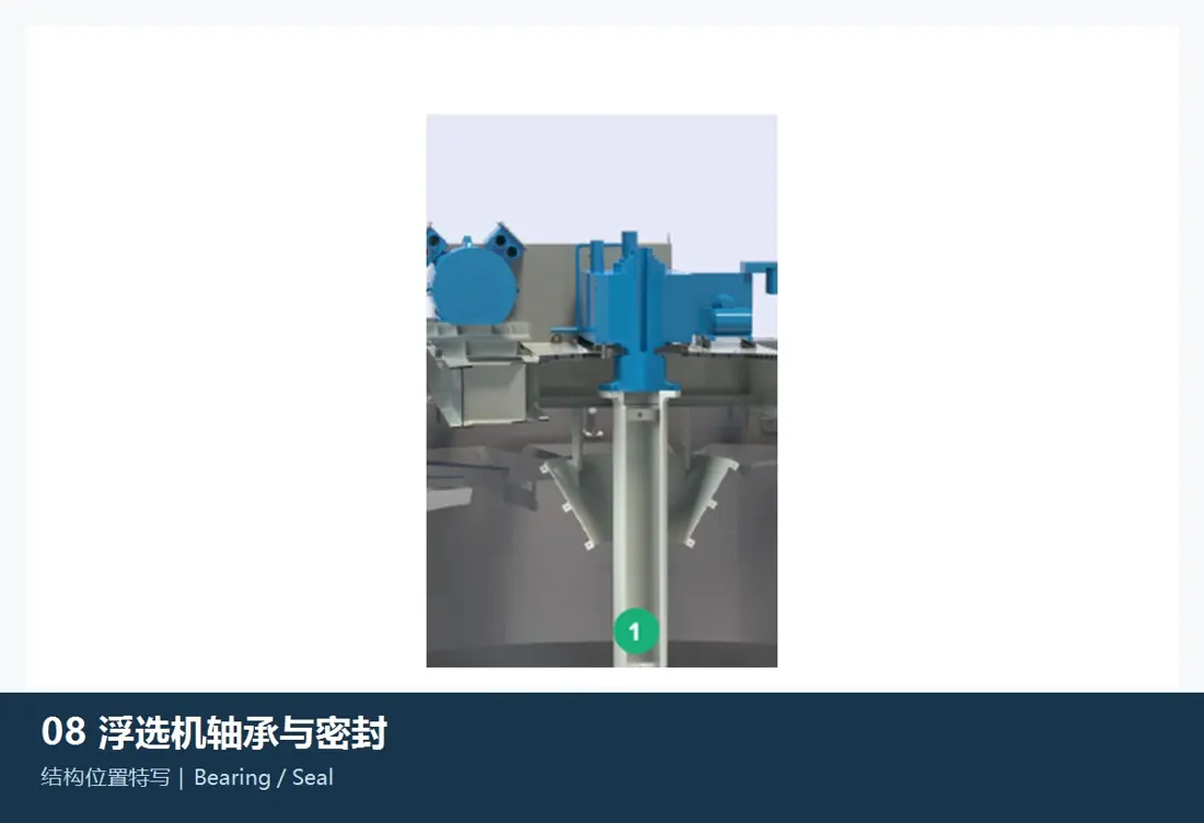
Bearings, Housing & Seals
Support rotating shafts and exclude slurry and moisture. Check bearing designation, clearance, housing bores, lubrication, seal combinations and upper-frame interfaces.
View the General Bearing and Seal Page →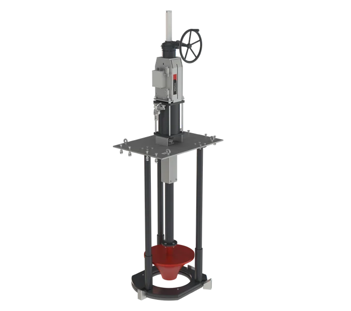
Dart Valve & Actuator
Includes stems, plugs, seats, guides, actuators and connections. Check cell position, stroke, pneumatic configuration and level-control logic when matching parts.
View the General Discharge Valve Page →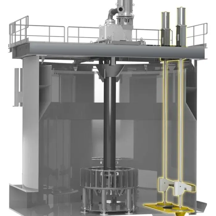
Level & Air Control
Includes level sensing, control valves, air distribution, flow control and pipe fittings. Confirm instrument ranges, valve specifications, control method and site connections.
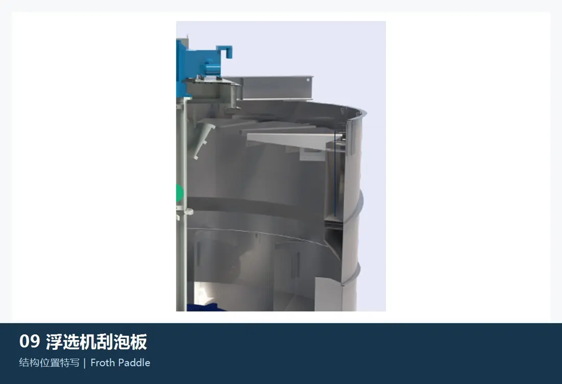
Launder & Froth Collection
Includes centre launders, froth guides, crowders and scrapers. Check tank diameter, supports, flow paths, corrosion-resistance requirements and connections.
View the General Froth Collection Page →Tank, Frame & Internals
Includes tank sections, upper frames, support beams, platforms and internal connections. Verify against general arrangements, loads, interfaces, corrosion exposure and site installation conditions.
Provide the series, effective volume or full model, serial number, mixing-mechanism version, drawing, position, current-part photographs, material and duty.
No. Cells of the same volume can differ in mixing-mechanism generation, shaft interfaces, stator base, covering materials and drawing revision. These require verification before manufacture.
Select rubber, polyurethane, ceramic, polyethylene or metal-based designs using part position, slurry chemistry, solids concentration, particle size, speed and failure mode together with the original drawing.
Browse component descriptions, drawing requirements and enquiry details.
Provide the full model, serial number, nameplate, position, current-part photographs, drawings, material and duty. These support part identification, material assessment, production at certified foundries, quality control and finished-part delivery.
Or contact us directly: +86 156 3797 3199
zzx@anranst.com
ANRANST provides customers worldwide with engineering assessment, production at certified foundries to the customer technical requirements, quality control and finished-part delivery for custom wear parts and industrial spares, with scope to support other custom industrial parts.
We review mating surfaces and interface dimensions and assess material, heat treatment and manufacturing feasibility.
Material grades and heat-treatment processes are specified order by order, stated in the technical agreement and tracked through production.
Drawing confirmation, material and process control, production tracking, inspection and acceptance coordination.
We coordinate manufacturing, quality confirmation, packaging and delivery of complete finished parts in a workable, closed-loop supply process.
Provide the existing model, drawings, drawing, materials or operating conditions so we can identify the appropriate technical review and supply route.
Submit an Enquiry