
HEAVY-DUTY DRIVE COMPONENTS
Heavy-Duty Mechanical Drive Spares
Confirm FirstDrive Type and Installed Layout
Then EstablishTorque, Speed, Ratio and Rotation Direction
InterfacesShaft Diameter, Key, Spline, Flange and Base
SupplyDrawing, Material, Heat Treatment, Inspection and Matched Set
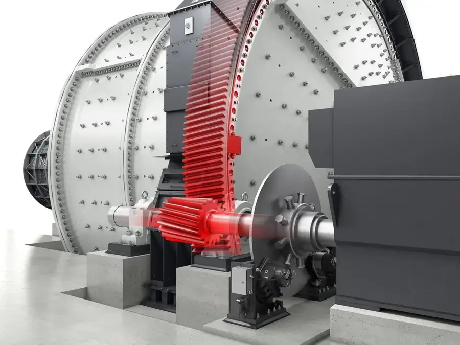
System scope Power input Power, Speed, Torque, Rotation Direction and Starting Duty Shaft system interfaces Shaft Diameter, Keys, Splines, Flanges, Alignment and Axial Position Auxiliary Drive Inching, Clutching, Braking, Backstopping and Interlocks Support and Lubrication Bearings, Seals, Oil Circuits, Cooling, Bases and Guards
Identify the Drive Architecture Before Separating Manufacturable Mechanical Parts
The same equipment category may use gear drive, gearless drive, direct drive or another OEM-specific arrangement. Shafts, couplings, brakes, inching drives, bearings, bases and lubrication interfaces from different architectures are not interchangeable.
Ring gears and pinions use the separate Gear page. This page focuses on connected shafting, couplings, gearbox mechanical parts, brakes and inching drives, bearing seals and structural interfaces.
Mechanical Spare-Part Scope
Confirm Each Part by Its Position in the Torque Path
Do not replace by generic name. First establish the input end, output end, rotation direction and adjacent interfaces.
Couplings and Connecting Shafts
Confirm type, rated and peak torque, speed, shaft diameter, key or spline, flange, spacing, axial movement and alignment.
Gearbox Mechanical Spares
Confirm complete machine model, stages, ratio, gear shafts, output shaft, housing, bearings, oil seals, rotation direction and mounting faces.
Inching Drive and Clutch
For maintenance inching or low-speed positioning, confirm engagement position, clutch method, speed, torque, interlocks and disengaged state.
Brake and Backstop Mechanical Parts
Confirm braking torque, application point, disc or drum dimensions, friction pair, release method, clearance and safety interlocks.
Bearings, Seals and Lubrication
Confirm bearing type, clearance, load, lubricant, flow, pressure, filtration, cooling, oil seals and contamination control.
Housings, Bases, Guards and Hardware
Confirm mounting holes, dowels, elevation, center distance, stiffness, shims, fastening, lifting and guarding clearances.
Part — Material — Duty
Material Selection Follows Load, Heat Treatment, Friction Pair and Manufacturing Route
Material families support initial selection. Confirm the final grade, properties, process and inspection from drawings and the technical agreement.
Do not infer alloy grade, hardness, case depth, tooth geometry, bearing designation or seal material from photographs. Establish materials and heat treatment together with dimensions, loads, machining allowance, fits and inspection requirements.
Failure Diagnosis
Investigate Vibration, Temperature Rise, Leakage and Fracture Across the Entire Drive Train
Replacing one part without checking alignment, lubrication and adjacent components can repeat the failure.
| Observed condition | Priority checks | Improvement Options |
|---|---|---|
| Abnormal Coupling or Shaft-Line Vibration | Alignment, soft foot, axial position, foundation, key or spline, rotor balance, bearings and torsional vibration | Restore shaft-line alignment and connection condition before defining the replacement scope |
| Bearing Temperature or Lubrication Alarm | Clearance, load, oil, flow, pressure, filtration, cooling, seals, contamination and journal | Treat bearings, lubrication, seals and shaft-line operating conditions as one system |
| Fatigue Damage to Shaft, Key or Spline | Peak torque, stress concentration, material heat treatment, fit, reverse impact, alignment and surface defects | Assess material, construction and process from the load spectrum and fracture surface |
| Gearbox Noise or Tooth-Surface Damage | Ratio, contact, bearings, housing alignment, lubrication, load distribution, foundation and input/output alignment | Measure the complete machine before defining repair scope for gears, shafts, bearings or housing |
| Brake, Inching-Drive or Clutch Fault | Interlocks, clearance, friction pair, engagement, disengagement, torque, rotation direction, lubrication and operating sequence | Restore safety interlocks and mechanical interfaces before trial operation |
Drawings and Inquiry Details
Establish Spares by Drive Layout, Shaft Interfaces, Materials and Drawing Revision
Use model details only when they correspond to the installed component through a reliable drawing or spare-model details.
Equipment and Drive Identity
OEM, complete model, serial number, drive type, power, input/output speeds, ratio, torque, rotation direction and modification history.
Drawings and Matched-Set Relationships
Assembly number, model details, drawing, spare-model details, item position, left/right end, quantity and drawing revision.
Shaft system interfaces
Shaft diameter, length, keyway, spline, flange, hole pattern, axial spacing, alignment, center height and mounting face.
Operation and Auxiliary Systems
Starting, stopping, inching, braking, backstopping, interlocks, lubrication, cooling, filtration, sealing and environmental conditions.
Materials and Manufacturing
Material, heat treatment, surface hardening, hardness gradient, casting or welding, machining datums, repair limits and batch.
Inspection and Failure Records
Dimensions, fits, NDT, tooth surfaces or journals, vibration, temperature, oil analysis, fracture surface, wear and replacement history.
Related Equipment and Parts
Closed Loop Across Drive Spares, Materials, General Equipment and OEM Installed Equipment
General pages maintain material and failure logic; equipment and OEM pages establish the installed layout; drawing and interfaces complete the technical confirmation.
Ring Gears, Gears and Pinions Open the gear part page for material, tooth geometry and drawing-number checks. Bearings and Bushes Open rolling or sliding bearing support, material and fit checks. Shaft Pins and Special Fasteners Open connection, preload, positioning and matched-hardware checks. General Ball Mills Information Review relationships among the drive, rotating body, drive gears and main bearings. Metso Select / Premier Ball Mills Confirm by series, dimensions and installed drive layout. Transmission-Alloy Steel Material Page Review material-selection logic for shafts, gear shafts and coupling hubs.
Request a Heavy-Duty Mechanical Drive Spare-Parts Proposal and Quote
Submit the equipment model, drive layout, assembly and part drawing, power and speed, shaft dimensions, materials and failure records.