
Industrial liners & wear linings
Industrial liners and wear linings
Select materials and structures by equipment position, operating conditions and failure mode
Liners protect the equipment body and may also participate directly in crushing, grinding, conveying or slurry flow. Components called liners can have very different loads and interfaces. Identify the equipment, installation position and wear mechanism before selecting metal, rubber, composites, ceramics or polymers.
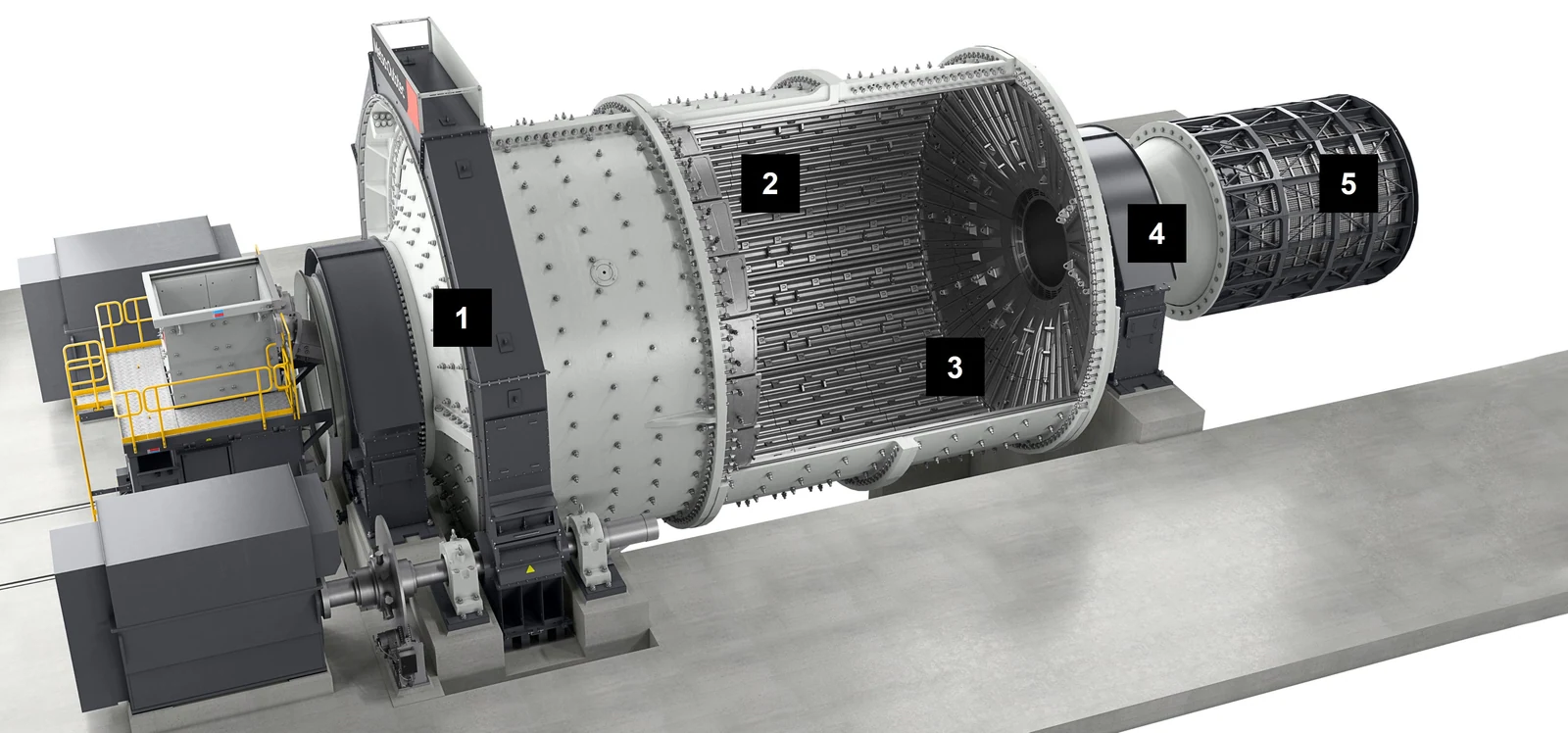
Grinding systemsSAG, AG, ball, rod, tower and vertical roller mills
Crushing systemsGyratory, cone, jaw, impact and hammer crushers
Conveying and slurry handlingChutes, bins, HPGR, hydrocyclones, slurry pumps and screening equipment
Identification requirementsComplete model, installation position, drawing, material, operating conditions and wear records
Engineering scope Equipment identification OEM, complete equipment model, serial number and structural version Installation interfaces Position, handedness or upper/lower orientation, adjacent parts, interfaces, hole positions and fastening Operating conditions Material handled, particle size, impact, abrasion, temperature, corrosion and flow velocity Supply identification Drawing and model details, used-part measurements, material, inspection and complete-set scope
First establish the liner's function in the machine
Mill liners protect the shell while controlling media lift and pulp discharge. Crusher mantles, concaves and jaw plates form the crushing surfaces. Chute and bin liners resist falling-material impact and sliding abrasion. Hydrocyclone and slurry pump linings also face high-speed slurry erosion, corrosion and local cavitation.
This page therefore organises product links by equipment function. Confirmed OEM drawing, model details and applicable models belong on the corresponding product pages. Liners from different equipment should not be combined into an ambiguous product merely because they share a name.
Grinding equipment
Mill liner systems
Liners at different positions jointly determine protection, media trajectories, discharge and maintenance intervals.
SAG mill feed-end liners
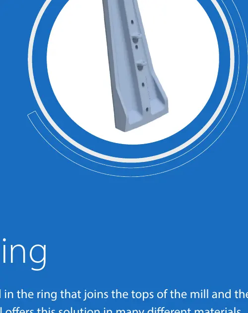
Protect the feed end against combined impacts from large ore pieces, steel balls and pulp. Check inner and outer rings, sectors, bolts and adjacent lifting structures.
Ball Mill Shell Liners
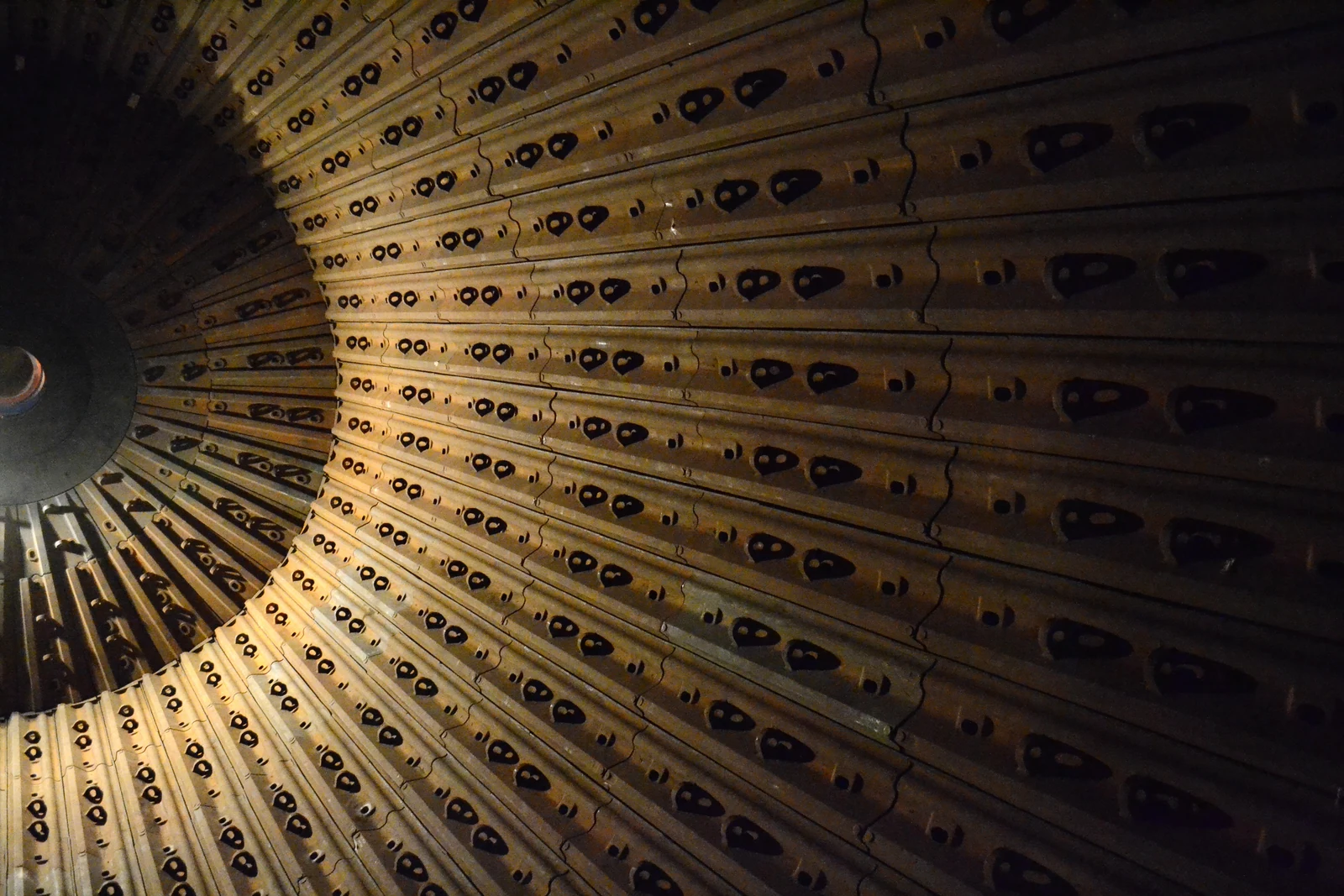
Protect the shell and control grinding-media motion together with lifter bars. Check mill dimensions, discharge type, liner layout, thickness and fastening system.
Rod mill shell liners
Profiles must accommodate steel rod motion and avoid abnormal tangling or impact. Check shell sections, profile, layout and end transitions.
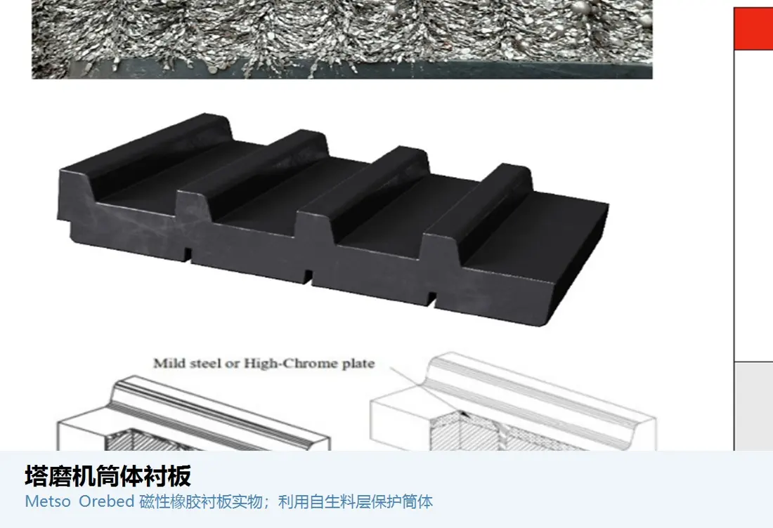
Tower and stirred mill housing liners
Separate grinding media from the housing under continuous abrasion and pulp washing. Identify by shell section, screw clearance and fastening method.
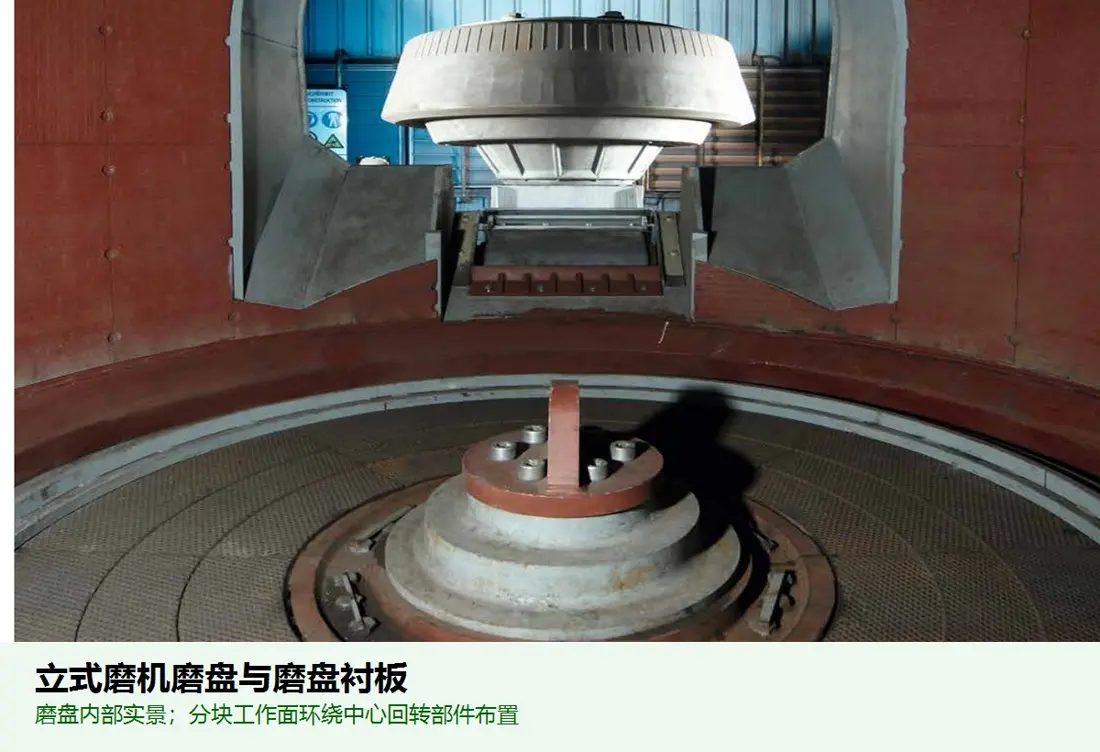
Vertical roller mill grinding table liners
Form the material-bed grinding surface with the rollers. Check table diameter, segment positions, worn profile, clamping structure and weld-overlay or casting route.
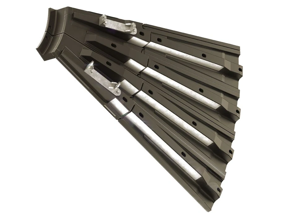
Mill head liners
Protect the heads and feed/discharge transitions. Check sectors, inner and outer rings, feed or discharge orientation, centre openings and fit with adjacent liners.
Crushing equipment
Crushing surfaces and frame protection liners
Crushing surfaces directly determine chamber profile and product size. Protective liners prevent wear to costly structural components.
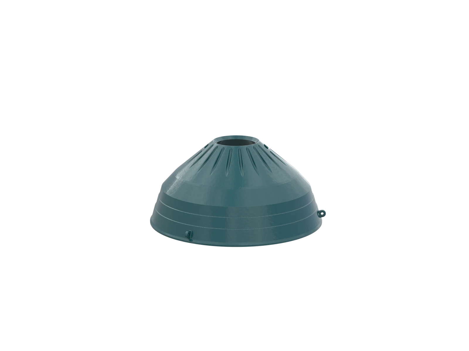
Cone Crusher Mantles
Form the inner moving crushing surface. Check equipment series, chamber profile, crushing stage, feed, closed-side setting and matching concave.
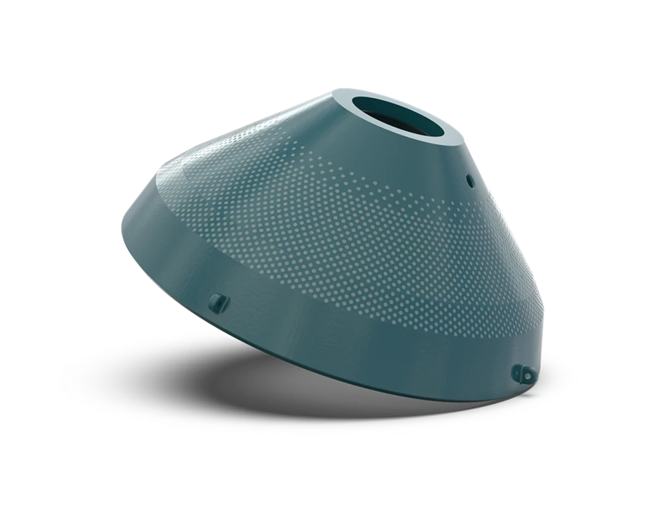
Cone crusher concave liners
Form the outer stationary crushing surface. Match the mantle chamber profile and check upper, middle and lower sections, support and backing method.
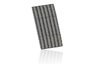
Fixed Jaw Plates
Pair with the movable jaw plate to form the crushing chamber. Check tooth profile, segments, reversible installation, clamping wedges and backing contact.
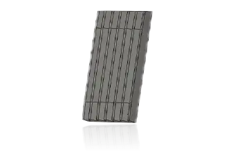
Movable jaw plates
Move with the swing jaw under alternating impact. Match the fixed jaw tooth profile and check holes, support and clamping orientation.
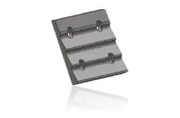
Impact apron liners
Receive high-speed material thrown by blow bars and produce rebound crushing. Distinguish impact and wear conditions in the first, second and third apron zones.
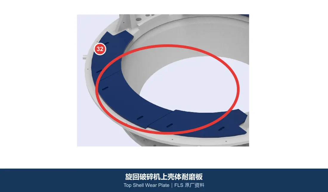
Gyratory crusher shell wear plates
Protect the upper shell and falling-material impact zones. Identify by shell segment, installation orientation, holes, adjacent concaves and material flow direction.
Material conveying and slurry handling
Linings for falling-material impact, sliding abrasion and slurry erosion
One machine may combine metal, ceramic, rubber, polymer and composite materials at different positions.
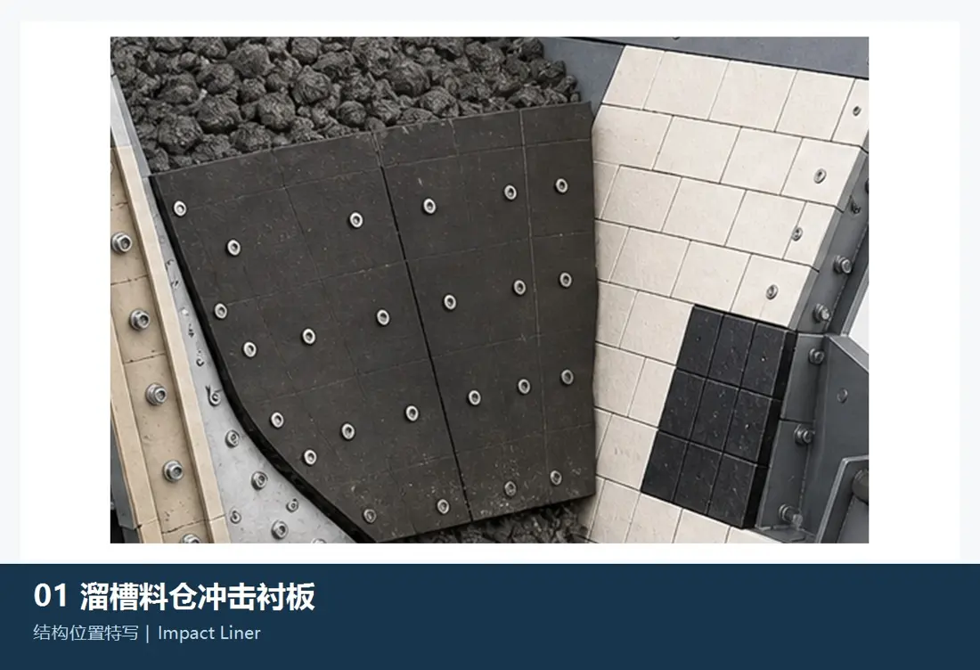
Chute impact liners
Fit at drop points and abrupt changes in flow direction. Check drop height, particle size, impact angle, underlying cushioning, fastening and maintenance space.
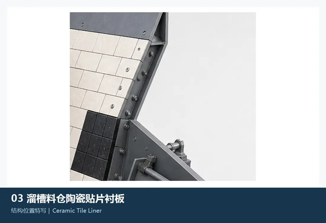
Ceramic and composite liners
Suit highly abrasive areas with controlled impact. Check ceramic form, rubber or steel backing, bonding, vulcanisation or mechanical fastening, and temperature.
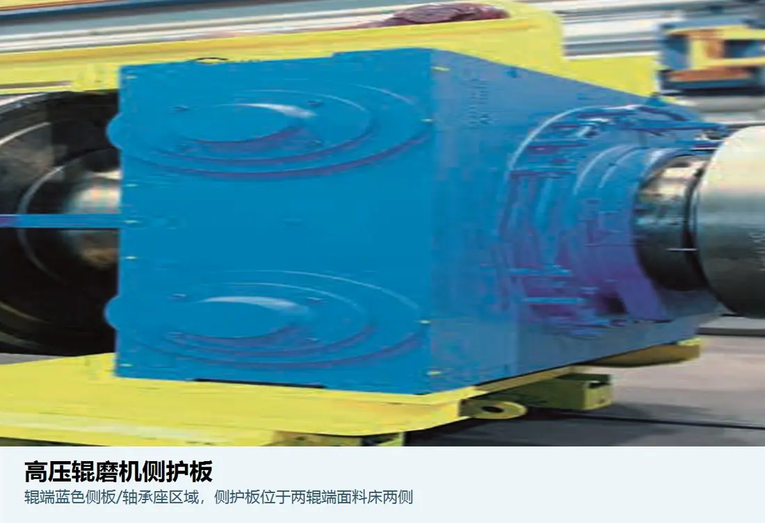
HPGR cheek plates
Contain the material bed at the sides of the roll gap and protect side structures. Check roll arrangement, side clearance, wear profile, segments and wear-layer structure.
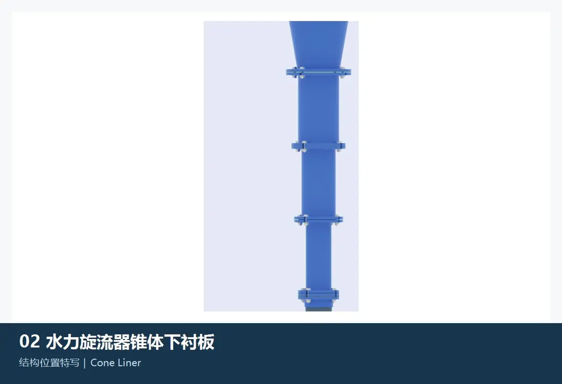
Hydrocyclone cone liners
Resist erosion from rapidly rotating slurry and concentrated solids. Check cyclone diameter, cone section, interfaces, internal profile and elastomer or ceramic system.
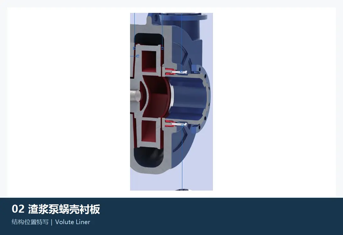
Slurry pump volute liners
Form flow passages and protect the pump casing. Match the impeller, front and rear liners, clearances and pump model. Select materials for particles, corrosion and temperature.
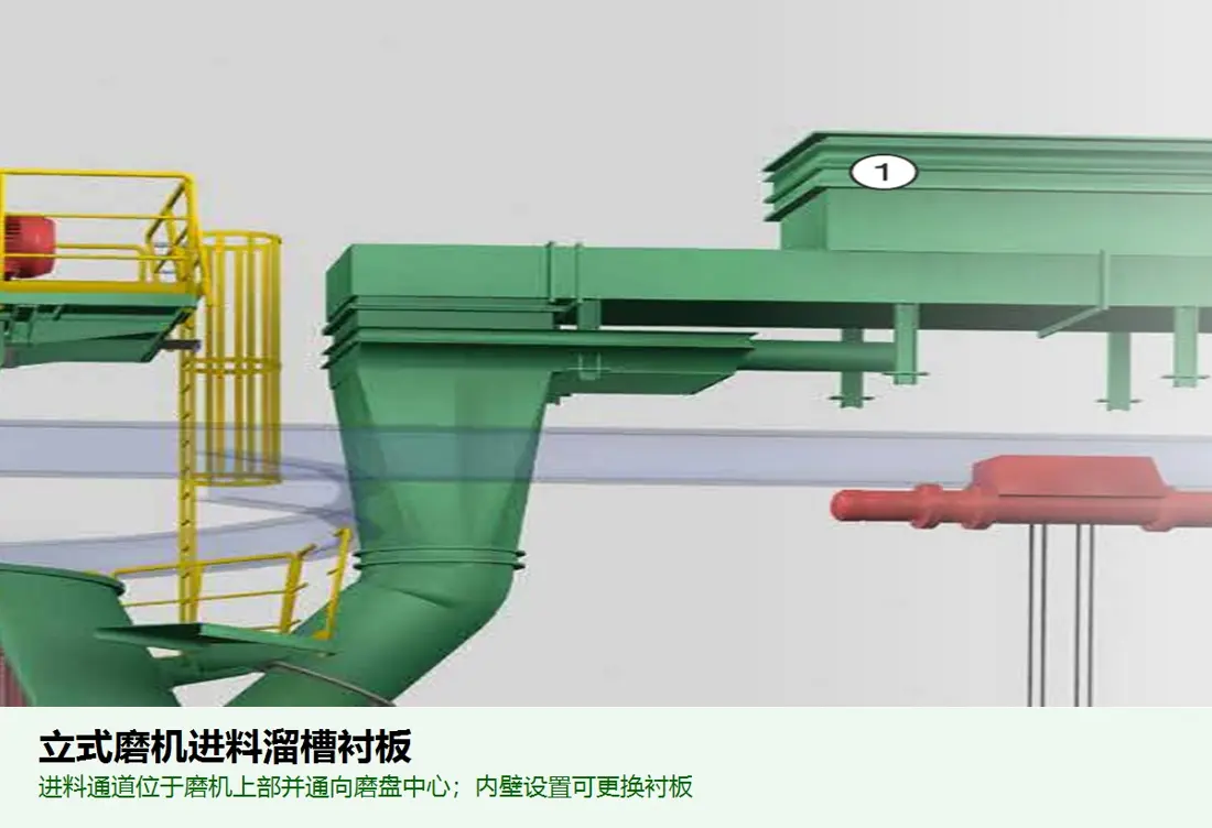
Feed and discharge chute liners
Protect material passages at equipment inlets and outlets. Check plate dimensions, materials and fastening separately for different drop points, flow directions and temperature zones.
Materials, performance and position
A material family is a starting point for selection, not a universal answer
Confirm final materials, heat treatment and structure against equipment position, drawings, operating conditions and failure evidence.
Failure diagnosis
Trace wear patterns back to structure, operating conditions and materials
Abnormal liner life should not be addressed simply by increasing hardness.
| Typical Symptoms | Priority checks | Possible adjustments |
|---|---|---|
| Premature local wear-through | Concentrated flow, impact angle, adjacent gaps, reversed installation, voids or poor support | Layout, thickness gradient, cushioning, material zoning and fastening |
| Cracks, broken sections or chipped edges | Peak impact, material toughness, abrupt section changes, casting defects, heat treatment and bolt preload | Material strength and toughness, fillets and sections, heat treatment, support and assembly |
| Rapid loss of mill liner profile | Media size, speed, charge level, ore changes, liner arrangement and lifting height | Profile, material combinations, layout and complete-set replacement timing |
| Ceramic detachment or exposed backing | Impact, bonding or vulcanisation, mechanical fastening, backing deformation, temperature and mounting surfaces | Composite structure, element dimensions, fastening method and cushioning |
| Rubber tearing, bulging or ageing | Sharp foreign objects, temperature, process media, backing corrosion, fastening and rubber compound | Compound, thickness, metal inserts, edge protection and sealing |
| Loose fasteners or slurry leakage | Hole positions, contact faces, bolt grade, washers, preload, liner settlement and replacement procedure | Fastening system, assembly process, reinspection interval and coordinated supply |
Enquiries and quality control
Liner supply information and inspection scope
Use traceable installation and failure information to define procurement, manufacturing and acceptance requirements.
Equipment and installation position
OEM, complete model, serial number, mill, crushing-chamber or flow-passage type, position number and adjacent parts.
Drawings and dimensions
OEM drawing and model details, latest drawing revision, used-part photos, key dimensions, holes, thickness and interfaces.
Operating conditions and process media
Material handled, particle size, hardness or abrasiveness, impact, flow rate and velocity, temperature, corrosion and foreign objects.
Materials and manufacture
Chemical composition, heat treatment, mechanical properties, hardness distribution, composite interfaces, welding, vulcanisation, bonding and traceability.
Failure history and objectives
Service life, wear measurements, cracking, fracture or detachment records, shutdown windows and throughput targets.
Acceptance and complete sets
Dimensions, material, non-destructive testing, hardness, matching bolts, installation markings, packaging and on-site trial-assembly requirements.
Technical references: Metso mill liner information combines metal, rubber, Poly-Met composites and other linings according to mill position and operating conditions. Its mineral processing handbook identifies cone and gyratory crusher mantles and concaves, jaw plates and impact apron liners as surfaces directly involved in crushing.Metso Mill Liners · Metso Basics in Minerals Processing
Related Equipment and Parts
Shared product facts across equipment, OEM models, products and materials
General equipment and OEM routes lead to the corresponding product page. Drawings and models are published only when supported by evidence.
SAG and AG mills Head, shell, lifting and discharge liner systems. Gyratory and cone crushing Mantles, concaves, shell and frame protection. Chutes and bins Impact, sliding, dead and highly abrasive zones. OEM Brands & Models Identify dedicated liners and drawing by brand, series and complete model. Materials and Processes Select candidate material families by position, failure mode and inspection requirements.