
Wear Parts / Lining Systems
Shell Lining Systems
Mill Shell Liner Components
Protects tower mill, stirred mill and HIGmill bodies. Identify technical and RFQ requirements by installed height, wear mechanism, material construction, equipment model and drawing.
Equipment HIGmill and tower mills / stirred mills confirmed against drawings
Installation Position Mill body inner wall, bottom feed area and individual grinding stages
Operating Conditions Grinding media abrasion, slurry erosion, corrosion and local impact
Identification requirements Model, shell diameter, position, drawing and liner drawings
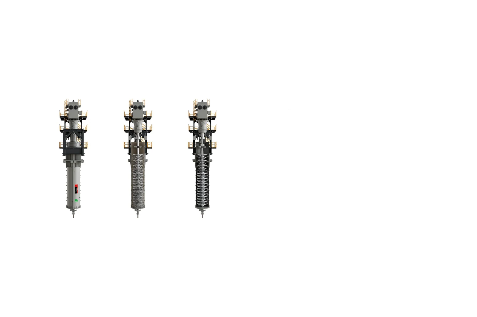
System functionIndividual Part Shell liners for a specific height or segment System configuration Combination of shell liners, stator rings and fasteners Key dimensions Curvature, thickness, segments, hole pattern and interfaces Quality priorities Dimensions, bonding, vulcanization, edges and fastening reliability
Liners vary with height and grinding stage
Shell liners separate the mill body from grinding media and slurry, protecting the pressure-containing shell and maintaining the grinding chamber profile. The system comprises liners at different heights, with different segments and fastening arrangements.
A published HIGmill case used fully vulcanized rubber-coated stationary components and shell lining. Applying the same material approach to other tower or stirred mills requires confirmation of their structure, operating conditions and drawings; equipment category alone does not establish suitability.
Installation Position
Performance requirements by zone
Adjust materials and construction to the actual wear distribution, with specific requirements for each area of the mill.
Bottom feed zone
Media bed pressure, slurry velocity and local wear are generally higher here. Check thickness, attachment edges, local debonding and erosion grooves.
Middle grinding zone
Exposed to sustained media abrasion and continuous shear. Control liner thickness uniformity, segment joints and fit with the stator rings.
Upper discharge zone
Assess material and profile in relation to internal classification and media retention. Check thinning, curled edges, delamination and abnormal local wear.
Materials and Manufacturing
Match material candidates to the wear mechanism
Confirm the final formulation, hardness, reinforcement, bonding and vulcanization parameters against drawings, samples and the technical agreement.
Wear-resistant rubber and polyurethane For liners requiring media impact cushioning, noise reduction and resistance to slurry abrasion. Control tear resistance, resilience, abrasion resistance, bonding and compatibility with the process medium. Metal reinforcement with elastomer For composite liners combining structural support, mounting interfaces and a wear-resistant surface. Check reinforcement stiffness, coating thickness, interface bonding and edge sealing.
Models and drawing
Installed configurations and part references
Liners within one equipment series can differ with shell diameter, volume, grinding stages and modification version.
| Equipment / Model | Key part identification details |
|---|---|
| HIG3500/23000 | 23,000 L mill body; check height, segments, stator interfaces and site-specific modifications |
| HIG500/4000 | 4,000 L mill body; check curvature, thickness, coating and fastening arrangement |
| HIG25 / HIG5 | Test equipment; dimensions cannot be inferred from industrial units |
| Other tower mills / stirred mills | First establish whether the mill uses a separate shell lining system |
Match OEM drawing, third-party drawing and spare model details to the applicable model, position, material and drawing revision.
RFQ information
Shell liner identification information
If detailed records are unavailable, start with the nameplate, photographs inside the mill body and dimensions of used liners.
Equipment identification
OEM, full model, serial number and nameplate.
Installation Position
Bottom, middle, upper area or specific grinding stage.
Dimensions and fastening
Curvature, thickness, segments, hole pattern and fastening method.
Material construction
Rubber, polyurethane, metal reinforcement or composite construction.
Wear and service life
Failure photographs, thickness changes, delamination and actual replacement intervals.
Part references and drawings
OEM drawing, samples, spare model details and drawing revisions.
Related Equipment and Parts
Equipment, stators and materials
Check shell liners together with the equipment model, stator rings and material system.