
HIGmill Key Wear Parts
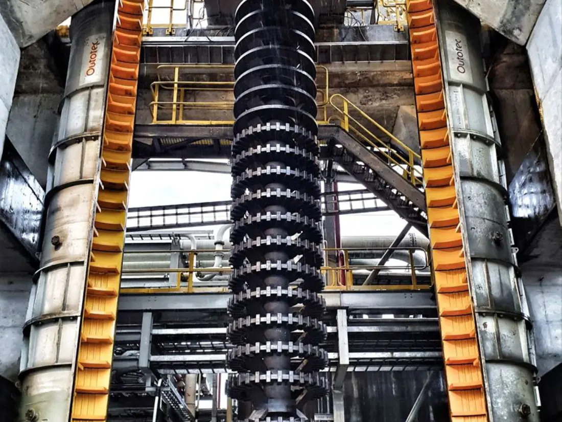
Shell-mounted Stator Rings
Shell-mounted Stator Ring
Fixed inside the HIGmill body, these rings work with shaft-mounted GrindForce rotors to form successive grinding stages. ANRANST coordinates identification, material assessment, manufacture and delivery according to the installed model, stator stage, working clearances and drawings.
Equipment Metso / Swiss Tower Mills HIGmill
Installation Position Stationary grinding stages inside the mill body
Operating Conditions Media wear, slurry erosion and rotor clearance control
Identification requirements Model, stage position, inside and outside diameters, hole pattern and drawings
Part FunctionIndividual Part Single-stage or segmented stator ring Assembly configuration Stator ring and shell liner combination Key dimensions Inside and outside diameters, thickness, segments and fastening interfaces Mating arrangement Matching rotor stage and working clearance
Stationary stator rings and rotors form the grinding stages
HIGmill OEM descriptions identify these as shell-mounted stator rings. The rings remain stationary while the rotors turn, together controlling shear and internal classification of ceramic media and slurry.
Stator rings at different heights in one mill may differ in inside diameter, thickness, segmentation and fastening. Confirm the rotor stage, working clearance, mill body diameter, used-part wear and current coating construction together.
Installation Position
Check wear and construction by stage position
Operating conditions vary with height, so stator rings should not be treated as identical parts.
Lower stages
Near the feed area, media bed pressure is higher. Check lining wear, local debonding, segment joints and fastening.
Middle stages
Provides continuous grinding and energy transfer. Check rotor clearances, roundness, thickness uniformity and fit with adjoining stages.
Upper stages
Near product discharge, assess profiles and remaining life in relation to media retention, slurry velocity and internal classification.
Materials and Processes
Match materials to the rotors and slurry conditions
Published projects include steel stationary parts, rubber-coated static rotors and fully vulcanized rubber shell lining. Confirm the applicable construction against the drawings.
Rubber-coated stator construction Cushions media impact and reduces metal surface wear. Control metal reinforcement, bonding, vulcanization, coating thickness and edge integrity. Wear-resistant alloy steel stationary parts For stages requiring higher stiffness, structural strength and dimensional stability. Confirm the steel grade, heat treatment and hardness according to impact and corrosion conditions.
Models and drawing
Applicable HIGmill configurations
Even mills with the same model designation may use different stator rings because of rotor upgrades, shell diameter, stage count or maintenance revisions.
| HIGmill Model | Key part identification details |
|---|---|
| HIG3500/23000 | Check the 23,000 L mill body, stator stage count, segments and matching rotor clearances |
| HIG500/4000 | Check the 4,000 L mill body, site-specific modifications and coating construction |
| HIG25 / HIG5 | Pilot or test equipment; dimensions cannot be inferred from industrial units |
| Other industrial HIGmill models | Identify by chamber volume, diameter, grinding stages and rotor configuration |
Record confirmed part references together with the applicable model, installed stage, drawing revision and material construction.
RFQ information
Stator ring identification information
If detailed records are unavailable, start with the nameplate, photographs inside the mill body and used parts.
Equipment identification
Brand, full model, serial number and nameplate.
Stator stage position
Stage positions from bottom to top, quantities and adjoining rotor positions.
Dimensions and interfaces
Inside and outside diameters, thickness, segments, hole pattern and fastening method.
Current construction
Steel, rubber-coated or composite lining construction, and current materials.
Wear condition
Thickness loss, debonding, cracks, deformation and time to failure.
Part references and drawings
OEM drawing, samples, spare model details and drawing revisions.
Related Equipment and Parts
Equipment, rotors and materials
Check stator rings together with the HIGmill model and matching rotors.