
HIGmill Key Wear Parts
GrindForce Grinding Rotors
GrindForce Grinding Rotor
Installed at individual grinding stages on the HIGmill main shaft, working with shell-mounted stator rings and ceramic media to form high-intensity grinding zones. ANRANST provides equipment identification, material assessment, drawing review, production quality control and delivery to drawings.
Equipment Metso / Swiss Tower Mills HIGmill
Installation Position Individual grinding stages on the vertical main shaft
Operating Conditions Media abrasion, shear and slurry erosion
Identification requirements Model, stage position, drawings and used-part dimensions
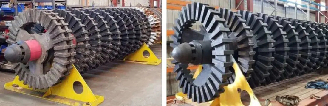
Part FunctionIndividual Part Individual grinding-stage rotor Assembly configuration Main shaft and multistage rotor assembly Key dimensions Outside diameter, thickness, shaft bore and connection design Quality control Materials, dimensions, balance and surface integrity
Rotor stage position determines duty and material selection
GrindForce rotors are mounted on the main shaft. Their castellated profiles agitate the grinding media and increase inter-media shear. Rotor diameter, thickness, interfaces and wear can differ between stages within one HIGmill.
Published projects show higher pressure and wear at the lower grinding stages, with both steel and rubber-coated castellated rotors in service. Before quotation, check the full model, rotor stage position, main shaft interface, rotation direction, current material and remaining dimensions.
Installation Position
Performance priorities by grinding stage
Use the following for preliminary selection alongside the installed drawings. Actual wear distribution also depends on media size and density, slurry concentration, speed, throughput and ore properties.
Lower grinding stages
Near the bottom feed area, media bed pressure and wear are generally higher. Check thickness loss, rounded profiles, cracks and coating detachment.
Middle grinding stages
Provides continuous energy transfer. Check wear consistency between stages, rotor spacing, dynamic balance and clearance to the stator rings.
Upper grinding stages
Near the product discharge area, assess rotor profile and remaining life in relation to particle size, media retention and internal classification.
Materials and Processes
Select construction for the wear mechanism
Use the material pages for initial selection. Specify the final grade, hardness, coating construction, bonding method and acceptance criteria in the approved drawings and technical agreement.
Rubber-coated castellated rotors For duties requiring media impact cushioning and reduced metal surface wear. Check elastomer formulation, metal reinforcement, bonding and vulcanization quality. Wear-resistant alloy steel rotors For designs requiring higher stiffness, strength and dimensional stability. Confirm the steel grade and heat treatment according to impact, abrasion and corrosion conditions.
Models and drawing
Applicable HIGmill configurations
Identify each rotor by installed model, stage position and drawing for every RFQ. A shared part name does not establish interchangeability.
| HIGmill Model | Key part identification details |
|---|---|
| HIG3500/23000 | 3,500 kW, 23,000 L installation; check rotor stage count, diameter and main shaft interface |
| HIG500/4000 | 500 kW, 4,000 L installation; check rotor construction and site-specific modifications |
| HIG25 / HIG5 | Pilot or test equipment; configuration differs from industrial units |
| Other industrial HIGmill models | Identify by chamber volume, power, shell diameter and grinding-stage configuration |
Match confirmed third-party drawing, OEM drawing and spare model details to the applicable model, installed stage and drawing revision.
RFQ information
Provide this information to begin identification
If detailed records are unavailable, start with nameplate and used-part photographs so engineers can identify the additional measurements and drawings needed.
Equipment identification
Brand, full model, serial number and nameplate photographs.
Installation Position
Rotor stage position, assembly photographs and adjoining part relationships.
Part references and drawings
OEM drawing, sample, drawing revision or existing spare model details.
Key dimensions
Outside diameter, thickness, shaft interface, connection type and remaining dimensions after wear.
Current Material
Steel, rubber-coated, polyurethane or other construction, with known properties.
Operating conditions
Grinding media, speed, slurry concentration, particle size, throughput and time to failure.
Related Equipment and Parts
Explore installed models, equipment and materials
Use the OEM route to identify models and drawing, and the general equipment route to review part functions and materials. Bring these together here for technical review and an RFQ.