
SAG MILL OUTER FEED HEAD LINER
Outer Feed Head Liner
Outer head wear parts · Check as a set with inner head liners and the first shell liner ring
Protects the outer SAG mill feed head and connects the inner feed head liners to the shell lining system. ANRANST provides mill identification, material assessment, drawing review, quality control and finished-part delivery.
Part Function Annular band geometry Inner and outer radii, angle, radial width and liner thickness Shell transition Axial profile, overlaps, height differences and adjoining gaps Fastening system Hole positions, counterbores, seating surfaces, bolts and rear contact Set identification Segment count, position numbers, rotation direction, orientation and matching part references
Protect the outer head and complete the transition to the shell liners
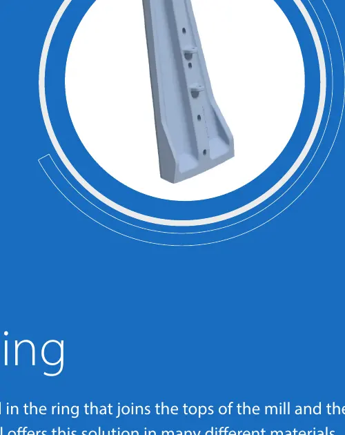
Outer liners occupy the large-radius area of the feed head, generally as sectors forming an annular band. They must form a continuous working surface with the inner head liners, first shell liner ring and fastening system.
For replacement, check the complete set for segment count, curvature, radial width, axial profile, hole positions, rib profiles, position numbers and adjoining part height differences.
Position and Performance
Prioritize transitions, support and profile retention at the outer head
A local material upgrade does not replace checking the adjoining liners and fastening system together.
Inner-ring interface edge
Joins the inner feed head liners. Check circumferential steps, gaps, concentrated impact and uneven wear.
Outer-ring working surface
Carries cyclic loads from ore and grinding media. Check profile retention, liner thickness, rear support and stresses around holes.
Shell transition edge
Joins the first ring of shell liners. Check axial height differences, overlaps, head-end impact and worn profiles.
Materials and Manufacturing Processes
Select the material system for impact, wear, support and weight
The approved drawings and technical agreement govern the final grade, chemical composition, heat treatment, hardness and acceptance criteria.
Mill heads, shells and discharge systems have different impact, abrasion and structural conditions. Select materials for the installed zone. Metso Mill Liners
Failure Diagnosis
Analyze outer-ring fractures, uneven interface wear and loose segments separately
Record wear profiles by position number to distinguish material, arrangement and fastening problems.
| Observed condition | Priority checks | Improvement Options |
|---|---|---|
| Cracking in the outer ring or around holes | Liner thickness, radii, hole positions, rear contact, preload, hardness and casting defects | Improve fracture resistance, transitions and support, and strengthen nondestructive inspection |
| Uneven wear at the shell interface | Axial height differences, overlaps, first shell liner ring, rotation direction and worn profiles | Adjust profiles and arrangement as a set to eliminate steps that concentrate impact |
| A loose segment or slurry leakage | Grip length, seating surfaces, washers, seals, bolt elongation and contact | Restore the fastening and sealing system, and record installation parameters by position |
| Large service-life differences within one ring | Uneven feed flow, position numbers, material batches, heat treatment, adjoining gaps and support | Map circumferential wear and optimize materials and profiles by zone |
Drawings and Inquiry Details
Identify each outer liner by installed mill, position number and shell interface
Match confirmed OEM drawing, third-party drawing and spare model details to the equipment model, installed position and drawing revision.
Equipment identification
OEM, series, full model, serial number, year, feed-end version and modification history.
Position and Identification
Position numbers, segment count, OEM drawing, third-party drawing, spare model details and drawing revisions.
Key dimensions
Inner and outer radii, angle, radial width, liner thickness, profile, hole positions, weight and orientation.
Adjacent Interfaces
Inner head liners, first shell liner ring, overlaps, height differences, gaps and fasteners.
Material and Service Life
Current material, hardness, heat treatment, composite construction, installation date, service life and remaining thickness.
Operating Conditions and Failure Modes
Ore, feed size, steel balls, throughput, uneven wear, cracks, looseness and site photographs.
Related Equipment and Parts
Connect equipment, OEM configuration, lining system and materials
Use this page to identify the individual part from either the general equipment structure or OEM configuration.
SAG Mill Lining Systems Explore the complete feed-end, shell, discharge and drive system. Inner Feed Head Liner Check the inner head wear parts adjoining the outer liners. SAG Mill Equipment Explore the complete machine structure and component locations. Metso SAG Mill Equipment Use the brand, series and model to identify the drawing.