
SAG MILL LINER SYSTEM
SAG Mill Lining Systems
Wear parts for high-impact grinding, feed ends and grate discharge, plus drive spares
Feed end and shellThroat liners, end liners, shell plates and lifter bars
Grate dischargeDischarge grates, pulp lifters and discharge cones
Drive sparesGirth gears, pinions and connecting fasteners
Identification requirementsModel, dimensions, drawing, liner layout and grinding conditions

System scope Installed equipment identification OEM, series, full model designation, serial number and year Key dimensions Internal shell diameter, effective length, end interfaces, hole positions and plate thickness Grinding conditions Feed size, ore characteristics, grinding balls, speed, filling level and throughput Delivery scope Liner zones, discharge system, fasteners, identification marks and installation documents
Build the BOM from the installed mill, liner layout and discharge arrangement
SAG mills of the same diameter may differ in shell length, feed-end design, grate openings, pulp lifters, hole patterns and drive configuration. Manufacturing requires the full model designation, serial number, drawing revision and measured dimensions.
Wear Parts
Feed-end and shell liners withstand large-rock impact and abrasive wear
Open each product to review its installation position, materials, drawing and enquiry requirements.
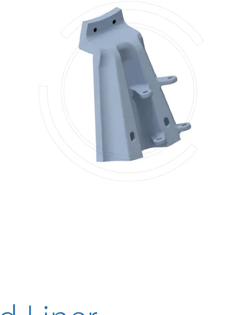 Feed inlet
 Feed Throat Liner
Protects the feed throat and guides large ore particles into the shell. Check internal and external profiles, flange hole pattern, axial length, interfaces and impact direction.
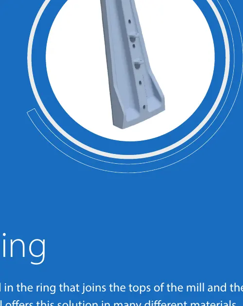 Outer feed-end ring
 Outer Feed Head Liner
Protects the outer ring of the feed head and meets the shell lining. Confirm segment geometry, hole positions, thickness, adjacent clearances and backing support.
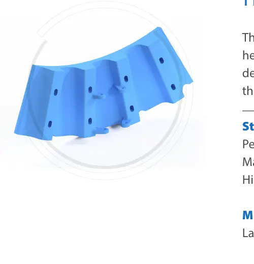 Inner feed-end ring
 Inner Feed Head Liner
Connects the throat lining to the head lining and withstands feed impact and cyclic grinding-media loads. Check the conical surface, center interface, hole pattern and direction of rotation.
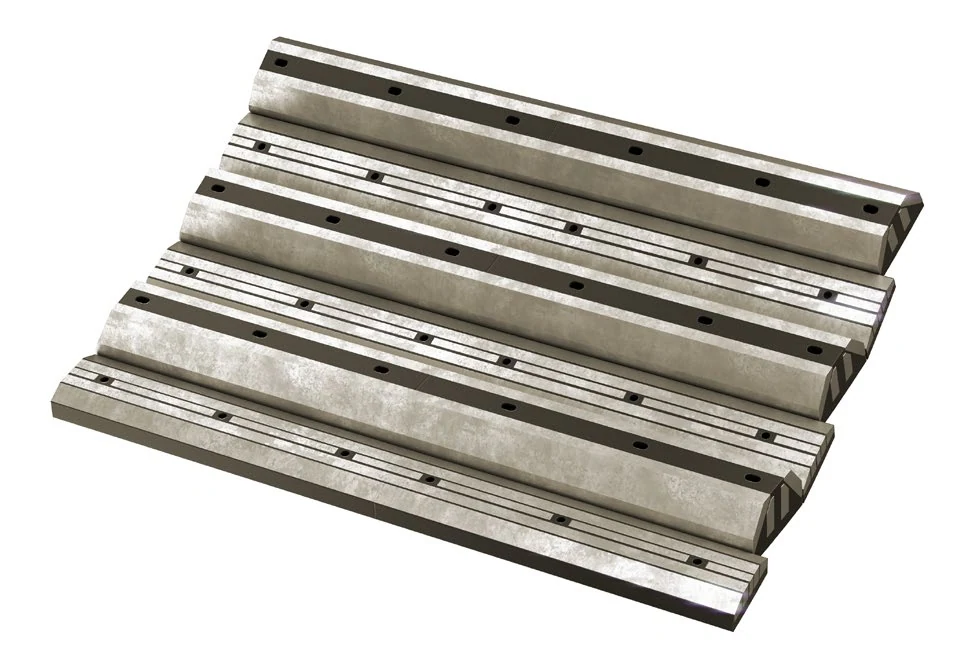 Shell grinding zone
 Shell Liners and Lifter Bars
Protect the shell and control the lifting, cataracting and cascading of ore and steel balls. Profile, height, spacing and worn contour directly influence grinding behavior.
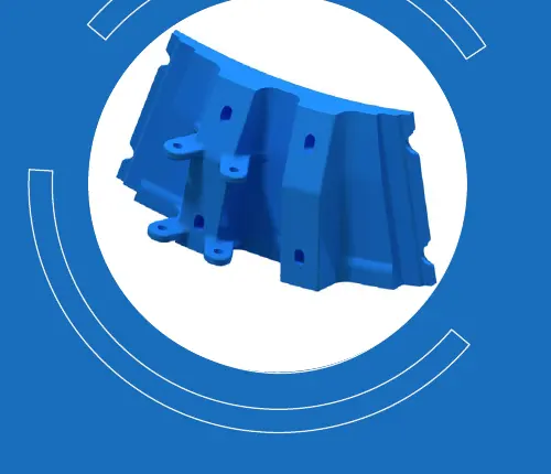 Discharge-end transition
 Intermediate Discharge-End Liner
Sits between the shell and grate-discharge structure, protecting the transition and maintaining continuity with adjoining parts. Check segmentation, hole positions and mating interfaces.
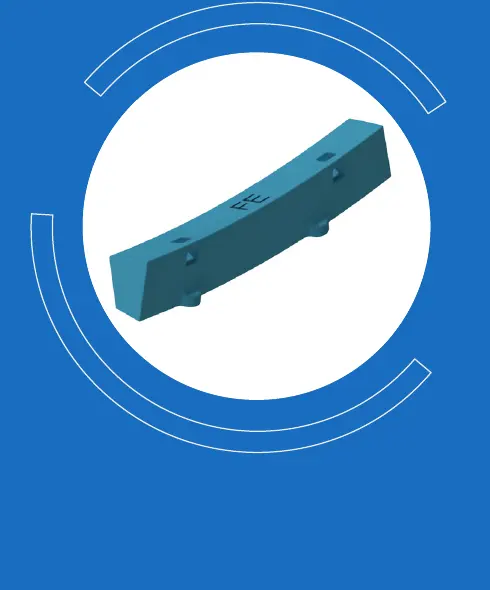 Liner connection zone
 Filler Ring
Fills local structural gaps in the lining system and maintains continuity of the liner arrangement. Verify position, curvature, cross-section, hole locations and adjacent-part dimensions.
Grate-Discharge System
Check discharge grates, pulp lifters and discharge cones as one continuous system
Openings, channel volume, direction of rotation and end interfaces jointly determine discharge capacity and material retention.
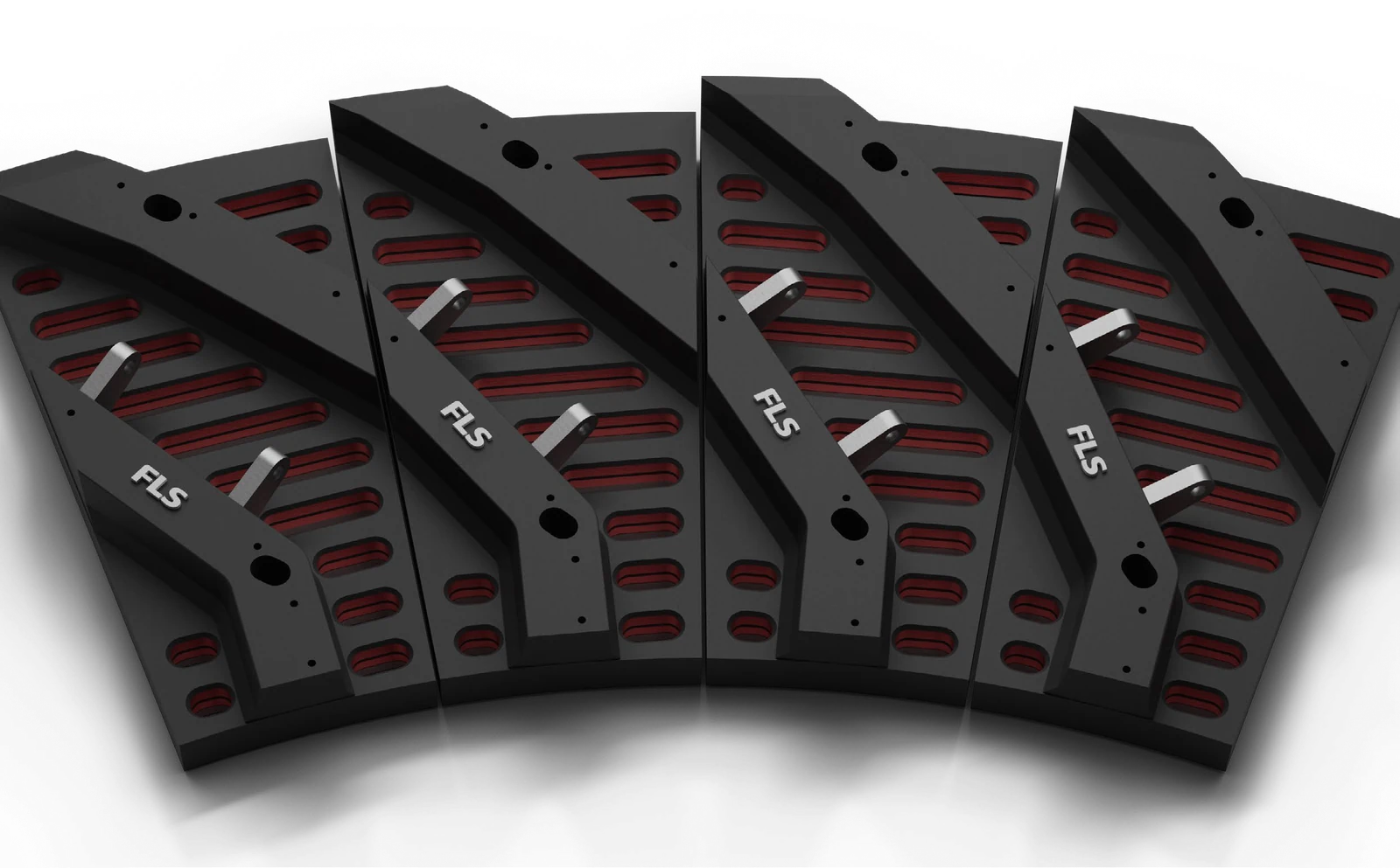 Screening and discharge inlet
 Discharge Grate
Controls the entry of slurry and correctly sized particles into the discharge chamber. Check slot size, open area, plate thickness, blinding, passage of broken grinding balls and the fastening arrangement.
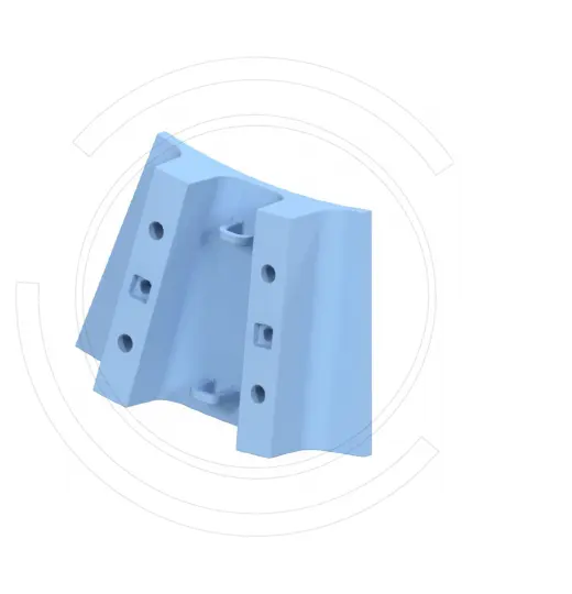 Inner discharge chamber
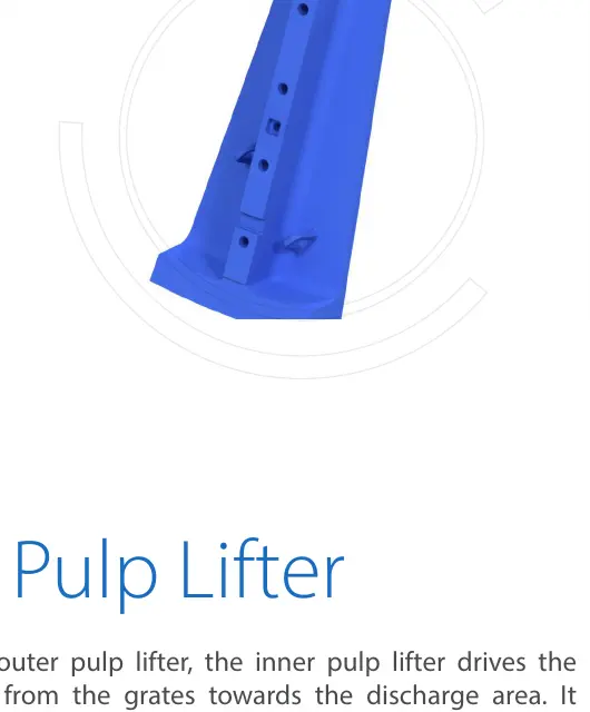
 Inner Pulp Lifter
Receives slurry passing through the grate and conveys it toward the center. Vane geometry, channel volume, direction of rotation and adjacent clearances must be checked together.
 Outer discharge chamber
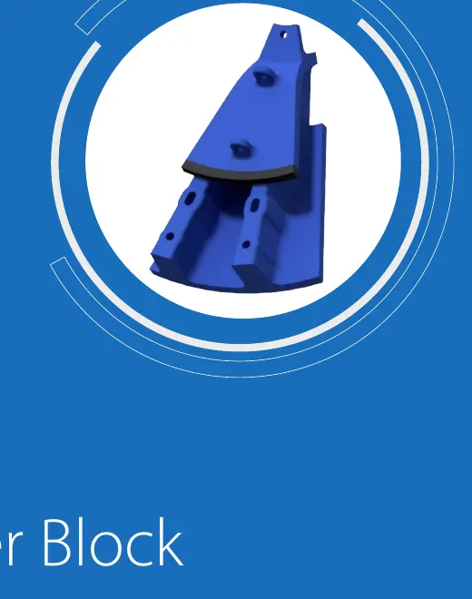
 Outer Pulp Lifter
Forms a continuous flow path with the inner lifter, grate and discharge cone. Confirm end interfaces, vane direction, support and wear allowance.
 Central discharge outlet
 Discharge Cone
Directs slurry from the pulp lifters toward the trunnion or downstream passage. Check cone angle, internal and external diameters, flanges, hole positions and wear lining.
 Complete lining system
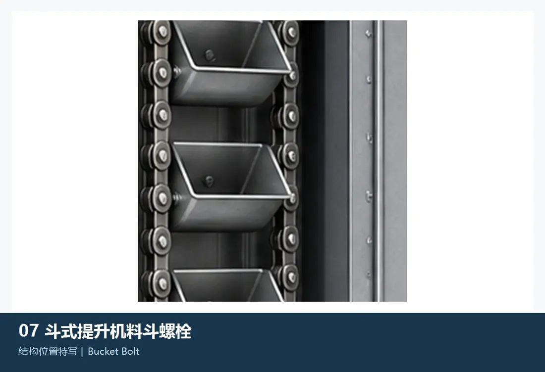
 Liner Bolts and Fastening System
Secure the rotating liners while maintaining sealing and preload. Verify head shape, thread, grip length, washers, seals, lubrication and the tightening method.
Spare Parts · Drive System
Specify girth gears and pinions as a matched mesh, with defined accuracy and mounting datums
Drive parts are separate from liners but are high-value SAG mill spares. Their drawing, materials, tooth system and inspection records require separate identification.
 Main drive
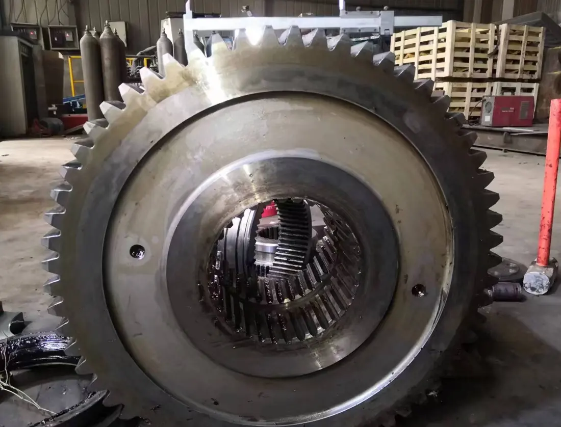
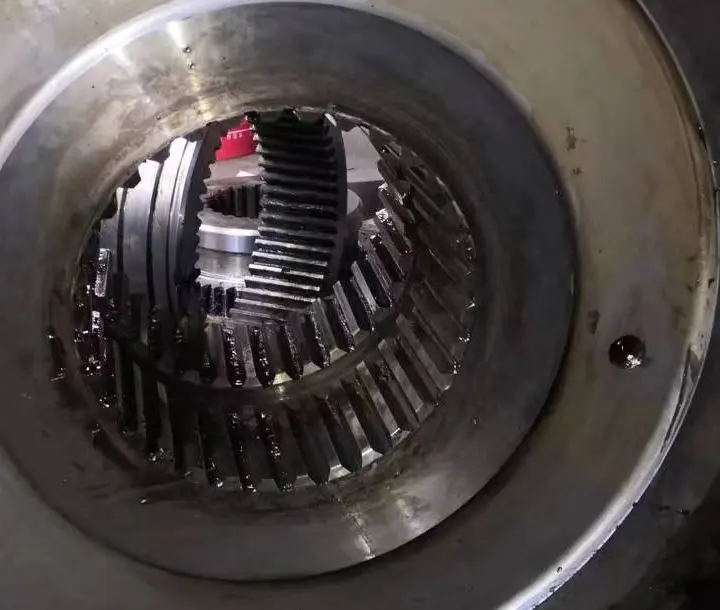
 Girth Gear / Ring Gear
Verify tooth system, module, tooth count, pressure angle, helix angle, split construction, flange hole pattern, runout and tooth-flank accuracy.
 Main drive mesh
 Drive Pinion
Check compatibility with the mating girth gear, tooth-flank accuracy, shaft journals, coupling interfaces, heat treatment, non-destructive testing and tooth contact.
 Load carrying and support
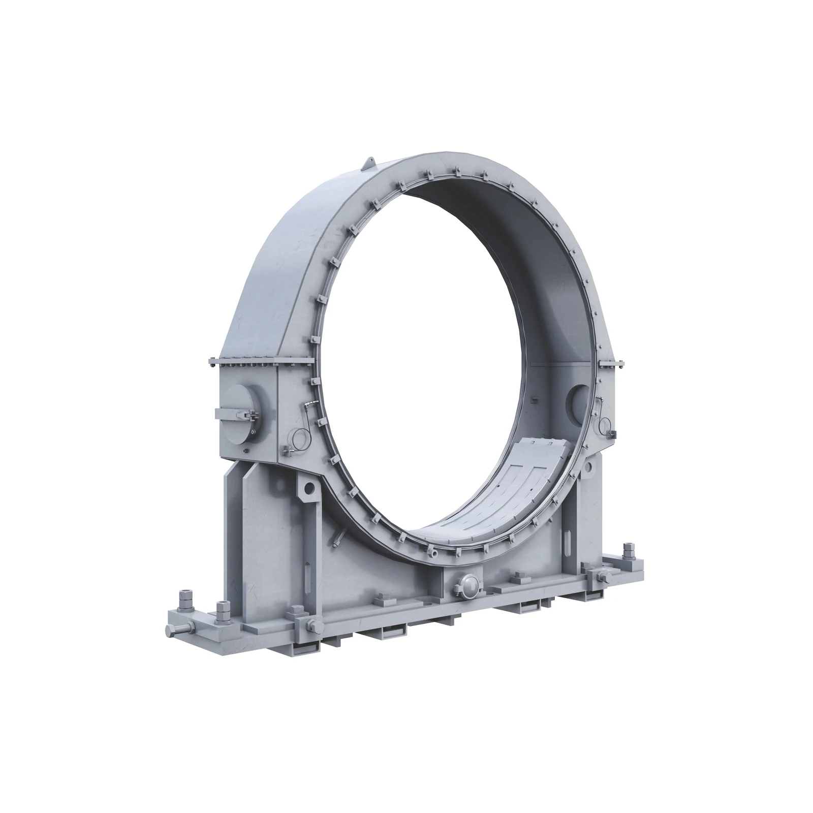
 Bearings, Bearing Liners and Support Spares
Specify bearings, bearing liners, seals, lubrication interfaces, housings and cooling arrangements for the actual mill support design. Do not assume interchangeability between models.
Materials, Positions and Performance
High-impact SAG duties require adequate material toughness first
These material families have defined application limits.
Lining selection: Mill heads, shells, discharge systems and trunnions serve different functions. Metso mill-lining options include metal, rubber and composite systems for these zones, with high-impact SAG duties requiring particular attention. Replacement parts must be specified against installed-equipment drawings and site operating conditions. Metso Mill Liners · Metso Grinding Mill Parts
Operating Conditions and Failure Modes
Assess the system through wear profiles, crack locations and discharge performance
The hardness of one part cannot explain the life of the complete lining system or the mill throughput.
| Observed condition | Priority checks | Material and design considerations |
|---|---|---|
| Premature lifter height loss or fracture | Large-rock impact, profile, spacing, speed, filling level, backing support and stress around holes | Ensure toughness and continuous support first, then improve profile retention and wear resistance |
| Uneven feed-end liner wear or loosening | Uneven feed distribution, lump size, segmentation, hole positions, seating, bolt preload and adjacent clearances | Select materials by impact zone and restore backing contact and the complete fastening system |
| Grate blinding or reduced discharge capacity | Slots, open area, broken grinding balls, slurry concentration, lifter capacity, direction of rotation and channel wear | Optimize grates, inner and outer pulp lifters and the discharge cone together; avoid changing a slot in isolation |
| Erosion perforation of discharge parts | Local flow velocity, backflow, particles, channel geometry, thickness and steps between adjacent parts | Select wear materials by flow zone and check transitions and replaceable working surfaces |
| Gear pitting, uneven loading or abnormal vibration | Girth-gear runout, mounting datums, contact pattern, lubrication, bearings, alignment and tooth-flank accuracy | Restore accuracy and maintain heat-treatment and installation records for the matched gear pair |
RFQ and Quality Control
Enquiry Requirements for SAG Mill Wear Parts and Spares
These details define the BOM, drawing, materials, manufacturing, inspection, installation sequence and delivery scope.
Mill identification
OEM, full model designation, serial number, year of manufacture, internal shell diameter, effective length, direction of rotation and drive type.
Lining and discharge drawings
General arrangement, liner layout, grate and lifter configuration, discharge cone, hole positions, direction of rotation and adjacent-part relationships.
Drawings and key dimensions
drawing, model details, revisions, curvature, thickness, profiles, interfaces, hole spacing, weights and fasteners.
Grinding conditions
Ore, feed size, abrasiveness, grinding-ball specification, filling level, speed, slurry conditions, throughput and discharge performance.
Existing parts and failure history
Material, hardness, installation date, service life, remaining thickness, wear measurements, cracks, loosening and failure photographs.
Inspection and delivery
Material, heat treatment, dimensions, non-destructive testing, weight, trial assembly, zone identification, BOM, fasteners and installation documents.
Related Equipment and Parts
Connect SAG mill designs, OEM models, parts and materials
Explore mill design and operating conditions, identify OEM series and drawing, and review individual parts for materials, dimensions and enquiry requirements.
SAG Mill Equipment Explore the machine structure, principal systems and related general-purpose parts. OEM Brands & Models Identify the installed equipment by brand, series, full model designation and historical configuration. General Liners and Wear Plates Compare liner functions and material options across equipment positions. Gears and Pinions Review drive-part materials, accuracy, heat treatment and enquiry requirements. Materials and Manufacturing Processes Select candidate material families by operating conditions, failure modes and manufacturing constraints.