
SAG MILL INNER PULP LIFTER
Inner Pulp Lifter
Inner discharge channels · Check together with outer lifters and the discharge cone
Receive slurry from the discharge system and direct it toward the central outlet. ANRANST provides channel identification, material assessment, drawing review, quality control and finished-part delivery.
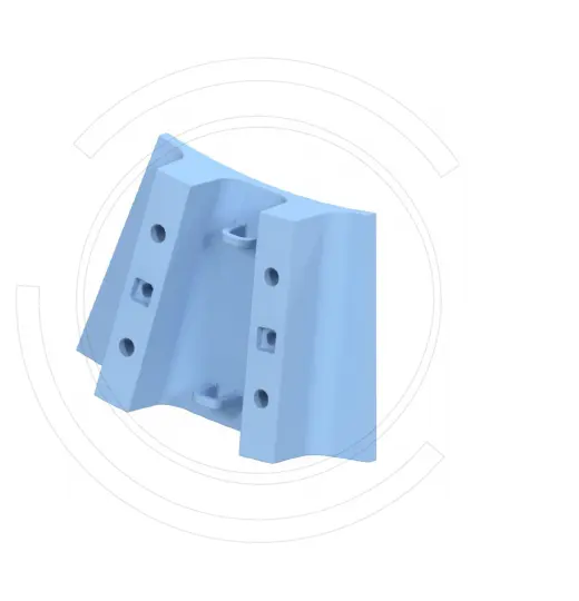
Part Function Channel Geometry Radial length, depth, width, vanes and outlet area Direction and Position Rotation direction, position number, inner or outer side, top/bottom and quantity per set Adjacent Interfaces Outer lifters, discharge cone, grate backs and central passage Mounting and Fastening Hole locations, counterbores, seating faces, fasteners, seals and rear support
Carry Slurry from the Discharge Chamber to the Central Outlet
Inner pulp lifters occupy the channels near the center of the discharge system, connecting the outer lifters to the discharge cone. Channel volume, vane direction, radial position and worn profile affect slurry transport and flowback.
Before replacement, check mill rotation, position numbers, inner and outer radii, channel depth, interface steps, hole locations and the quantity per set.
Channels and Performance
Wear Differs at the Inlet, Vanes and Central Outlet
Record wear and erosion along the flow path to assess material selection and geometry.
Outer Inlet
Receives slurry from upstream lifters. Check local impact, flow-direction changes, steps and uneven inlet wear.
Vanes and Channels
Continuously lift and direct slurry. Check working-surface erosion, particle abrasion, grooving and changes in channel volume.
Central Outlet
Connects to the discharge cone or central passage. Check outlet area, flowback, interface steps and local perforation.
Fastening and Support
Carries cyclic loads and bolt preload. Check cracks around holes, looseness, rear-surface erosion and seating.
Materials and Manufacturing Processes
Select Materials for Erosion, Abrasion, Impact and Support Conditions
The final grade, heat treatment, hardness and acceptance criteria depend on the agreed drawing, installation position and operating conditions.
Select materials for the continuous discharge path formed by the grates, inner and outer pulp lifters and discharge cone. Metso Mill Liners
Failure Diagnosis
Locate Restricted Discharge, Flowback, Perforation and Fracture
Record wear locations together with flow direction, mill rotation and adjacent parts.
| Observed condition | Priority checks | Improvement Options |
|---|---|---|
| Reduced discharge or increased mill hold-up | Channel volume, vane profile, rotation direction, grate openings, outer lifters and flowback | Assess grates, inner and outer lifters and the discharge cone as a complete system |
| Localized inlet or outlet perforation | Flow direction, particles, interface steps, plate thickness, material and local velocity | Improve transitions and wear surfaces; vary material and thickness by location along the flow path |
| Cracked vanes or broken sections | Impact, section size, fillets, support, preload, hardness and casting defects | Improve toughness and support continuity, and strengthen non-destructive inspection |
| Wear around holes or looseness | Grip length, seating faces, washers, seals, rear contact and slurry ingress | Restore the complete fastening and sealing system and record installation data by position |
Drawings and Inquiry Details
Identify Inner Lifters by Discharge Position, Rotation and Channel Design
Match drawing and spare model details to the equipment, installation position and drawing revision.
Equipment identification
OEM, series, complete model, serial number, discharge-end version, rotation direction and modification history.
Position and Identification
Position number, inner or outer side, quantity, drawing, sample, spare model details and revision.
Channel Dimensions
Inner and outer radii, radial length, width, depth, vanes, outlet area and direction.
Mounting Interfaces
Hole locations, counterbores, seating faces, outer lifters, discharge cone, rear channels and fasteners.
Material and Service Life
Current material, hardness, heat treatment, composite construction, installation date, service life and remaining thickness.
Operation and Failure
Slurry, particle size, flow rate, throughput, flowback, erosion, cracks, looseness and photographs.
Related Equipment and Parts
Discharge Grates, Inner and Outer Lifters and Discharge Cone
Each section of the channel affects the others. Complete the assessment against the OEM model and discharge general arrangement.
Discharge Grate Check openings and flow capacity at the discharge system inlet. Outer Pulp Lifter Check the upstream outer channels and rotation direction. Discharge Cone Check the central discharge outlet and interfaces. SAG Lining and Discharge System Return to the complete system and inquiry requirements. Metso SAG Mill Equipment Identify the installed machine by brand, series, model and drawing.