
SAG MILL DISCHARGE CONE
Discharge Cone
Central discharge transition wear part · Check together with the inner pulp lifters and central outlet
Directs slurry from the inner pulp lifters to the central discharge opening. ANRANST provides component identification, material assessment, drawing review, quality control and finished-part delivery.
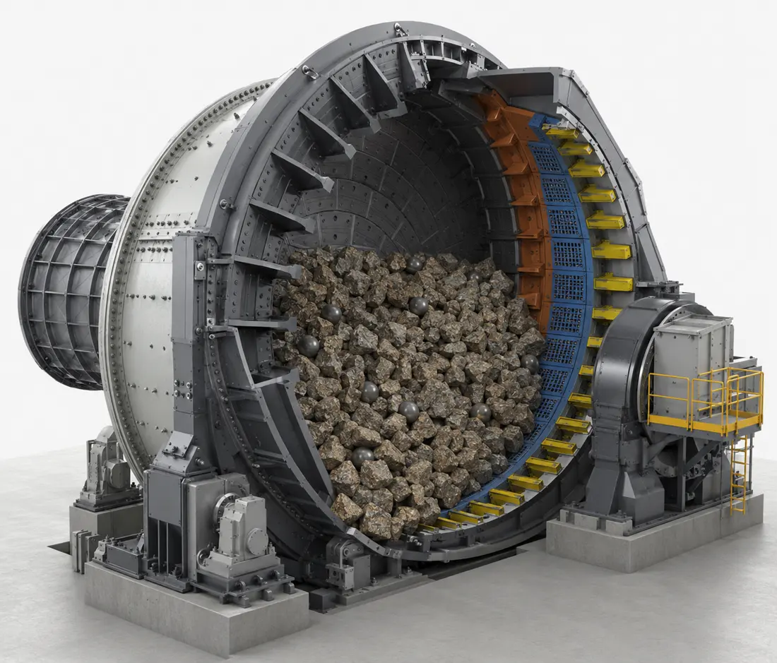
Part Function Cone profile Cone angle, generatrix, large- and small-end diameters, axial height and transition radii Segments and positions Position numbers, segment count, left/right or upper/lower arrangement and assembly sequence Adjacent Interfaces Inner lifters, central outlet, mill head structure and sealing areas Mounting and Fastening Hole locations, counterbores, seating faces, fasteners, seals and rear support
Connect the inner lifter channels to the central discharge opening
The discharge cone is a segmented or annular transition at the centre of the discharge end. Its cone profile, central opening, axial position and inner lifter interfaces together determine the continuity of the discharge path.
For replacement, check segment count and positions, cone angle, large- and small-end diameters, axial height, hole pattern, interface steps and central outlet.
Position and Performance
Check the inlet transition, conical flow path and central outlet separately
Record wear and erosion locations relative to the flow direction to assess material, thickness and profile.
Inner lifter interface
Check the inlet cross-section, interface steps, misalignment, backflow and local particle impact.
Cone working surface
Check for sustained erosion, grooves, local thinning, segment joint wear and profile changes.
Central Outlet
Check the opening dimensions, outlet wear, blockages, seals and adjoining chute interface.
Fastening and Support
Check for cracks around holes, looseness, erosion behind the part, joint condition and continuous support.
Materials and Manufacturing Processes
Select material candidates for the erosion, impact and support conditions in the central channel
The final grade, heat treatment, hardness and acceptance criteria depend on the agreed drawing, installation position and operating conditions.
Check the discharge cone as part of the continuous flow path through the inner and outer pulp lifters and discharge grates. Metso Mill Liners
Failure Diagnosis
Locate backflow, grooving, perforation and loose segments separately
Record each failure location together with the flow direction, segment, interface and adjoining lifter.
| Observed condition | Priority checks | Improvement Options |
|---|---|---|
| Restricted discharge or backflow | Inner lifter interfaces, cone profile, central opening, misalignment, blockages and worn cross-sections | Restore a continuous flow path and check the complete discharge system |
| Grooving or local perforation of the cone | Flow direction, particles, interface steps, plate thickness, material and local velocity | Refine the transitions, thickness and working-surface material according to the flow direction |
| Cracked or fractured segments | Section geometry, radii, support, preload, hardness, residual stress and manufacturing defects | Improve toughness and support continuity, and strengthen nondestructive inspection |
| Open joints or looseness around holes | Segment positioning, grip length, seating surfaces, washers, seals and rear contact | Restore positioning and fastening, and record installation data for each position |
Drawings and Inquiry Details
Identify the discharge cone by discharge-end version, segment position and central opening
Match drawing and spare model details to the equipment, installation position and drawing revision.
Equipment identification
OEM, series, complete model, serial number, discharge-end version, rotation direction and modification history.
Position and Identification
Position numbers, segment identifiers, quantities, OEM drawing, samples, spare model details and revisions.
Key dimensions
Cone angle, large- and small-end diameters, axial height, central opening, wall thickness and profile.
Mounting Interfaces
Hole positions, counterbores, seating surfaces, inner lifters, central outlet, joints and fasteners.
Material and Service Life
Current material, hardness, heat treatment, composite construction, installation date, service life and remaining thickness.
Operation and Failure
Slurry, particle size, flow rate, throughput, flowback, erosion, cracks, looseness and photographs.
Related Equipment and Parts
Coordinate the grates, inner and outer lifters, and central discharge cone
Each section affects the rest of the discharge path. Final identification requires the OEM model and discharge assembly drawing.
Inner Pulp Lifter Confirm the upstream flow channels and discharge cone interfaces. Outer Pulp Lifter Check the outer discharge channels and direction of rotation. Discharge Grate Check the openings and flow capacity at the discharge system inlet. SAG Lining and Discharge System Return to the complete system and inquiry requirements. Metso SAG Mill Equipment Identify the installed machine by brand, series, model and drawing.