
SAG MILL DISCHARGE GRATE
Discharge Grate
Wear parts at the grate discharge inlet · Check with pulp lifters and the discharge cone
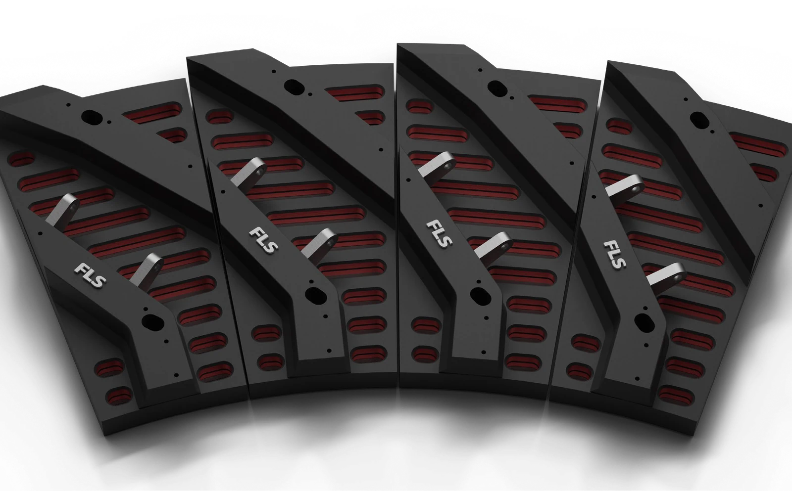
Retains grinding media and oversized particles in the mill while allowing slurry and suitably sized particles into the discharge chamber. ANRANST provides opening identification, material assessment, drawing review, quality control and finished-part delivery.
Part Function Segment geometry Sector angle, inner and outer radii, grate thickness and profile Discharge openings Slot width, opening length and shape, arrangement and effective open area Mounting Interfaces Hole positions, counterbores, seating surfaces, fastening and adjoining part height differences System parameters Rotation direction, lifter channels, discharge cone and target flow rate
Control particle size, flow and the inlet to the discharge chamber
Grates are arranged in zones at the discharge end. Their working surfaces withstand ore and steel ball impacts, while slots and opening shapes determine slurry and particle passage. They form the inlet to the discharge system.
For replacement, check segments, position numbers, slots or opening shapes, open area, thickness, rotation direction, hole positions and interfaces with intermediate liners and pulp lifters.
Position and Performance
Working surfaces, slot edges and support areas face different risks
Maintain flow capacity while preventing excessive opening enlargement, fracture and unintended passage of grinding media.
Mill-side working surface
Withstands impacts from large ore and steel balls. Check surface wear, cracks, chipped edges and safe remaining thickness.
Slots and openings
Exposed to abrasive cutting and slurry erosion. Check opening enlargement, rounding, blockages, broken grinding balls and changes in passing particle size.
Rear surface and lifter interface
Directs material into the discharge chamber. Check rear erosion, channel steps, rotation direction and adjoining lifter capacity.
Hole areas and fastening
Carries preload and cyclic loads. Check counterbore wear, seating contact, loose bolts and cracks around holes.
Materials and Manufacturing Processes
Balance impact toughness, opening wear resistance and structural integrity
The final grade, heat treatment, hardness and acceptance criteria depend on the agreed drawing, installation position and operating conditions.
The mill discharge system is a distinct functional area. Its materials and structure must jointly meet flow, wear resistance and safety requirements. Metso Mill Liners
Failure Diagnosis
Address blockages, enlarged openings, fractures and low discharge rates separately
First determine whether the problem arises from the openings, material, discharge channels or operating conditions.
| Observed condition | Priority checks | Improvement Options |
|---|---|---|
| Blocked grate slots | Slot width, opening shape, feed, broken grinding balls, steel ball size, slurry concentration and foreign objects | Optimize openings with regard to lifter capacity and operating conditions; do not enlarge slots in isolation |
| Rapid opening enlargement | Flow velocity, particles, opening profile, material, hardness gradient and erosion direction | Improve opening profile retention and select materials or composite working surfaces for safe impact resistance |
| Cracked grate bodies or broken segments | Large-particle impact, ligament width between openings, radii, grate thickness, support, preload and casting defects | Improve toughness, section geometry and support, and strengthen nondestructive inspection |
| Reduced discharge capacity | Effective open area, mill hold-up, lifter channels, rotation direction, wear and backflow | Check the grates, inner and outer lifters, and discharge cone as a complete system |
| Loose bolts or wear around holes | Grip length, seating surfaces, washers, seals, preloading method and rear contact | Restore the complete fastening system and record installation data by position |
Drawings and Inquiry Details
Identify each grate by discharge-end position number and opening configuration
Match confirmed OEM drawing, third-party drawing and spare model details to the equipment, position, rotation direction and drawing revision.
Equipment identification
OEM, series, full model, serial number, shell dimensions, discharge-end version and rotation direction.
Position and Identification
Position numbers, segment count, OEM drawing, third-party drawing, spare model details and drawing revisions.
Opening data
Slot width, opening length and shape, arrangement, effective open area, permitted passing particle size and wear limits.
Key dimensions
Inner and outer radii, sector angle, grate thickness, ligaments between openings, mounting holes, counterbores, weight and orientation.
Adjoining systems
Intermediate liners, inner and outer pulp lifters, discharge cone, interface height differences, channels and fasteners.
Operating Conditions and Failure Modes
Ore, steel balls, broken grinding balls, slurry, throughput, blockages, cracks, opening wear and photographs.
Related Equipment and Parts
Match grates, pulp lifters and the discharge cone to the installed mill model
Discharge system components affect one another. An individual part page cannot replace checking the complete system.
SAG Lining and Discharge System Explore the complete range of wear parts, discharge components and drive spares. Inner Pulp Lifter Explore the inner conveying channels downstream of the grates. Outer Pulp Lifter Explore the outer discharge channels and interfaces. Discharge Cone Explore the central discharge outlet wear parts. Metso SAG Mill Equipment Identify the installed machine by brand, series, model and drawing.