
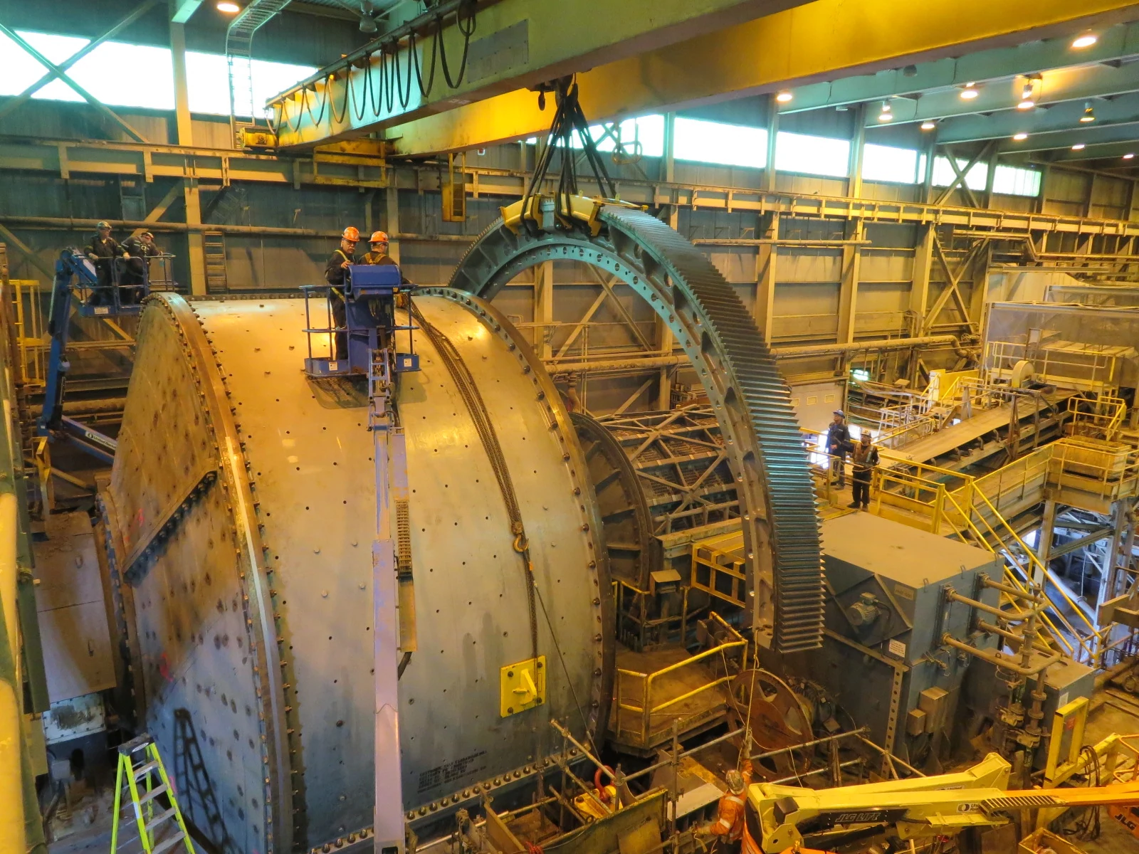
SAG MILL GIRTH GEAR / RING GEAR
Girth Gear (Ring Gear)
Heavy-duty split gear matched to the drive pinion · Installation accuracy governs contact and service life
Receives torque from the pinion to rotate the mill shell. ANRANST provides gear data review, material and heat treatment assessment, manufacturing coordination, quality control and finished-part delivery.
Drive function Gear parameters Module or diametral pitch, tooth count, pressure angle, helix angle, helix hand, profile shift and face width Segment joints Segment count, joint faces, location features, connecting bolts, pins and trial assembly requirements Mounting flange Locating register, bolt holes, pitch circle, axial position, shell interface and shims Matching gear data Pinion drawing, centre distance, backlash, contact pattern and tooth modification requirements
Transfer pinion input torque to the mill shell
Large girth gears are generally made in two or more segments. Manufacturing, transport and site assembly jointly determine the final tooth contact. Segment joints and the mounting flange are critical interfaces in addition to the gear teeth.
A girth gear cannot be manufactured from outside diameter, tooth count or photographs alone. Confirm it using the matching pinion data, mounting flange, centre distance, runout and drawings.
Girth gear performance
Control tooth flanks, roots, segment joints and installation runout separately
Assess manufacturing accuracy, site assembly, shell condition and lubrication together for heavy-duty open gears.
Tooth contact
Check tooth profile, lead, modifications, roughness, contact pattern, pitting and scuffing.
Tooth roots and rim
Check tooth root radii, material defects, rim section, fatigue cracks and residual stress.
Segment joint fit
Check joint-face contact, tooth misalignment, location features, bolt preload and tooth pitch continuity after trial assembly.
Installation runout
Check radial and face runout, shell deformation, flange contact, centre distance and backlash.
Materials and Manufacturing Processes
Select cast or forged steel according to the original design, dimensions, loads and manufacturing route
Specify material grade, hardness and accuracy class against the applicable drawings and standards.
Confirm materials and heat treatment together with relative pinion hardness, tooth contact, lubrication and operating loads. Metso Grinding Mill Parts
Failure Diagnosis
Address pitting, uneven loading, root cracks, segment misalignment and fastening problems separately
Provide tooth photographs, contact patterns, runout, vibration, temperature, lubrication and segment-joint records.
| Observed condition | Priority checks | Improvement Options |
|---|---|---|
| Tooth pitting or spalling | Contact stress, relative hardness, uneven loading, roughness, lubrication and contamination | Restore contact and lubrication, and review materials and heat treatment |
| One-sided or periodic uneven wear | Radial and face runout, centre distance, shaft alignment, shell deformation, flange and pinion bearings | Remeasure and correct the full-ring installation |
| Tooth root or rim cracks | Overload, root radii, casting defects, residual stress, heat treatment and rim section | Conduct nondestructive inspection and fracture analysis, and review manufacturing and loads |
| Tooth misalignment or abnormal contact at segment joints | Joint faces, location features, bolt preload, pins, trial assembly and site installation sequence | Restore segment joint alignment and tooth pitch continuity |
| Loose mounting bolts | Flange contact, hole pattern, bolt grade, preload, shell deformation and reinspection interval | Restore the fastening system and reinspect according to the procedure |
Drawings and Inquiry Details
Identify the girth gear by the complete gear pair, segments and mounting flange
Match confirmed OEM drawing, third-party drawing and spare model details to the equipment, gear pair and drawing revision.
Equipment and drive
OEM, full model, serial number, drive type, power, speed, operating conditions and modification history.
Drawings and segments
Girth gear drawing, segment drawings, assembly number, samples, spare model details, segment count and transport constraints.
Gear data
Tooth count, module or diametral pitch, pressure angle, helix angle, helix hand, profile shift, face width and accuracy.
Mounting Interfaces
Mounting diameter, locating register, flange, hole count and diameter, pitch circle, joint faces and axial position.
Matching components and site data
Pinion drawing, centre distance, backlash, contact pattern, radial and face runout.
Materials and inspection
Material standard, casting or forging route, heat treatment, hardness, mechanical properties, nondestructive inspection, tooth profile and trial assembly reports.
Related Equipment and Parts
Match the girth gear, pinion and materials to the OEM mill configuration
Girth gears are not interchangeable by equipment category. Confirm the complete gear pair and installation data.
Drive Pinion Check matching tooth data, centre distance and contact. Alloy Steels for Drive Parts Review casting, forging, heat treatment and quality requirements. General Gears and Pinions Explore drive components for different equipment types. SAG Mill Spare Parts System Return to equipment spare parts and RFQ requirements. Metso SAG Mill Equipment Identify the installed equipment by brand, series, model and drawing.