
SAG MILL SHELL LINER & LIFTER
Shell Liners and Lifter Bars
Core grinding-zone wear system · Managed by layout, profile and wear pattern
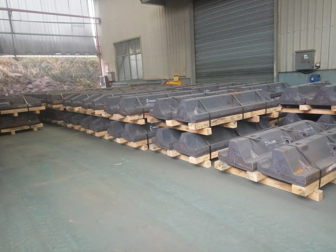
Protects the SAG mill shell and controls the lifting, cataracting and cascading of ore and steel balls. ANRANST provides lining layout identification, material assessment, drawing review, quality control and complete-set delivery.
Part Function Layout identification Row count, ring count, position numbers, orientation and quantities per set Lifter profile Height, angle, top width, working face and worn profile Shell interface Base curvature, liner width, hole positions, grip length and contact Complete Sets Liners, lifters, bolts, seals, identification and drawings
Protect the shell and maintain the intended charge motion
Shell liners provide a continuous protective surface, while lifter height, angle and spacing govern ore and steel ball motion. Liners and lifters may be separate or combined, but must always be checked against the full-ring layout and position numbers.
Similar segment shapes do not establish interchangeability. Mill diameter, effective length, row count, bolt holes, liner width, rotation direction and site modifications all affect the BOM.
Profile and performance
Impact and wear vary by location
Record wear separately on the lifter face, top, base and shell plate to assess profile and material performance.
Lifter working face
Directly moves ore and steel balls. Check impact, sliding wear, angle changes and local spalling.
Lifter top
Profile height governs charge lifting. Check the rate of height loss, rounding and charge trajectory as the lifter wears.
Base and hole areas
Carries structural loads and preload. Check rear contact, cracks around holes, looseness and grip length.
Shell liner working surface
Protects the shell against rolling grinding media and abrasion. Check liner thickness, grooves, erosion and perforation.
End transition rows
Loads and geometry differ near the feed and discharge ends. Check materials, profiles and adjoining parts separately in these rows.
Manholes and special positions
Manhole liners, short end liners and parts with special hole patterns cannot be replaced by standard-position liners. Supply them to their specific drawing and orientations.
Materials and Manufacturing Processes
Ensure toughness first, then optimize wear resistance for high-impact SAG duty
The material system depends on the position, ore, steel balls, profile, support and target service life.
Metso literature describes metal, rubber and composite mill lining systems and emphasizes matching liner design to operating conditions. Specify replacement parts against installed drawings and site wear data. Metso Mill Liners
Failure Diagnosis
Assess service life, throughput and downtime risk together
Pursuing hardness alone can turn a wear problem into fracture or fastening failure.
| Observed condition | Priority checks | Improvement Options |
|---|---|---|
| Premature lifter height loss and declining throughput | Profile, spacing, speed, filling, steel balls, feed and charge trajectory after wear | Optimize profile retention and layout, and improve wear resistance while maintaining the required toughness |
| Fractured lifters or detached fragments | Large-particle impact, abrupt section changes, rear support, hole positions, preload, hardness and casting defects | Improve toughness, continuous support, radii and nondestructive inspection |
| Shell liner perforation or grooving | Liner thickness, charge movement, steps between adjoining parts, local looseness, material and slurry erosion | Restore a continuous working surface and adjust liner thickness, profile and material by zone |
| Loose or broken bolts, or slurry leakage | Grip length, head shape, washers, seals, lubrication, preloading method and seating surfaces | Restore the complete fastening system and record torque or bolt elongation |
| Uneven wear within a ring or between adjoining rows | Uneven feed flow, position numbers, orientation, material batches, heat treatment and adjoining gaps | Map wear by position and adjust profiles and materials by zone |
Drawings and Inquiry Details
Identify every segment by liner layout drawing and position number
Match each confirmed OEM drawing, third-party drawing and spare model details to the equipment, row position and drawing revision.
Equipment identification
OEM, series, full model, serial number, shell inside diameter, effective length, rotation direction and modification history.
Layout and positions
Liner layout drawing, row count, ring count, position numbers, orientation, quantity per ring and complete BOM.
Drawings and dimensions
OEM drawing, samples, revisions, profiles, base curvature, width, length, hole positions and weight.
Fastening and interfaces
Bolt head shape, thread, grip length, washers, seals, rear contact and adjoining gaps.
Material and Service Life
Current material, hardness, heat treatment, installation date, service life, remaining height and wear profiles.
Grinding conditions
Ore, feed size, abrasiveness, steel balls, filling ratio, speed, throughput and failure photographs.
Related Equipment and Parts
Coordinate equipment, OEM configuration, lining system and fasteners
General part pages cover function and materials, OEM pages identify models and drawing, and fastener pages cover the complete fastening system.
SAG Mill Lining Systems Return to the complete feed-end, shell, discharge and drive system. Liner Bolts and Fasteners Check head shape, grip length, preload and sealing. SAG Mill Equipment Explore the complete machine structure and grinding conditions. Metso SAG Mill Equipment Identify drawing through the brand, series, model and installed configuration.