
BALL MILL DISCHARGE GRATE / GRATE PLATE
Ball Mill Discharge Grates
Key Grate-Discharge Wear Parts · Identified by Openings, Flow Channels and Position
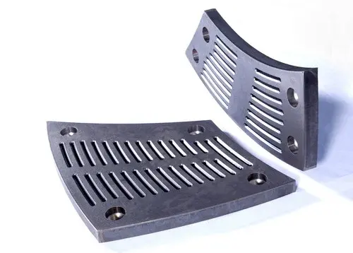
Discharge grates pass suitably sized slurry while retaining grinding media, directly affecting discharge capacity and circulation. ANRANST provides machine identification, slot and channel review, material assessment, quality control and delivery of matched sets.
Part Function Sector Identification Inner or outer ring, position number, orientation, angle and quantity Discharge openings Slot shape, width, length, open area and blockage control requirements Rear Flow Channels Flow direction, depth, adjacent pulp lifters and discharge interface Fastening interface Rear profile, hole positions, bolts, seating and sealing
Pass slurry while retaining grinding media in the mill
Grates are usually segmented around the discharge end. The working face retains balls and oversized particles, while openings pass slurry into rear channels. Pulp lifters then direct it towards the discharge trunnion.
Similar slots do not establish interchangeability. Discharge diameter, sector, rotation direction, radial position, thickness, rear channels, mounting holes and adjacent pulp lifters all determine part identity.
Position and Performance
Openings, flow, strength and wear resistance must work together
Larger openings can affect structural strength and media retention; extra thickness can also alter discharge capacity.
Working surface
Exposed to balls, ore and slurry. Check wear, impact depressions, cracks and remaining thickness.
Grate Openings
Control particle passage and effective open area. Check enlargement, distortion, blockage and chipped edges.
Grate Bars
Balance flow area and structural strength. Inspect weak sections, fatigue cracks and broken bars.
Rear Flow Channels
Direct slurry towards the pulp lifters. Check erosion, buildup, blockage, orientation and adjoining interfaces.
Mounting Hole Areas
Carry clamping and structural loads. Check cracks around holes, crushed seating surfaces, looseness and slurry leakage.
Sector Edges
Gaps and steps between adjacent plates affect flow and wear. Check position, orientation, edges and installation sequence.
Materials and Manufacturing Processes
Select Materials for Impact, Erosion, Grate Sections and Support
Use material families for initial selection; confirm the grade, properties, heat treatment and geometry against drawings and operating conditions.
Selection sequence: openings and flow channels → impact, erosion and section thickness → current failure modes → material and process → drawings and acceptance requirements.
Failure Diagnosis
Assess discharge capacity and structural integrity together
Blockage, enlarged slots, broken bars and loose grates affect throughput and downtime in different ways.
| Observed condition | Priority checks | Improvement Options |
|---|---|---|
| Blocked Openings and Reduced Discharge Capacity | Slot shape, dimensions, open area, slurry, particles, flow direction, adjacent pulp lifters and wear deformation | Restore the correct openings and channels, and check their suitability for the duty |
| Rapid Slot Enlargement | Ore abrasiveness, slurry, velocity, material, hardness, edge profile and local flow imbalance | Improve edge profiles, materials and local wear protection |
| Broken Bars or Detached Sections | Weak sections, impact, rear support, casting defects, heat treatment and abnormal ball impacts | Improve toughness and section continuity, with appropriate nondestructive inspection |
| Loose Grates or Slurry Leakage | Rear seating, hole pattern, clamping length, bolts, seals, preload and retightening | Restore the grates, fasteners and seals as a matched system |
| Uneven Wear between Adjacent Sectors | Position numbers, orientation, rear channels, gaps, material batches and pulp lifter interfaces | Map wear by position and optimise individual zones |
Drawings and Inquiry Details
Specify Grates by Sector, Orientation, Openings and Drawing Revision
Use the part or drawing for the specific installation position. Provide an drawing or spare model details when available.
Equipment identification
OEM, series, full model, serial number, shell diameter, EGL, discharge arrangement and modification history.
Sector and Position
Inner or outer ring, sector angle, position number, orientation, quantity, arrangement drawing and adjacent pulp lifters.
Drawing and Revision
drawing, spare model details, drawing revision, project number and markings on the part.
Openings and Flow Channels
Slot shape, width, length, quantity, open area, bar cross-section, rear channels and flow direction.
Structural Dimensions
Inside and outside diameter, sector, thickness, rear profile, hole spacing and diameter, counterbores, outline and weight.
Materials and Operating Conditions
Current material, properties, service life, slurry, particles, balls, throughput, blockage and failure photographs.
Related Equipment and Parts
Grates, Pulp Lifters, Equipment, OEMs and Materials
Review discharge function and materials, identify the installed OEM series, then confirm drawing and flow channels.
Pulp Lifters Check the channels behind the grates, orientation and discharge interface. Discharge End Liners Check adjacent sectors, inner and outer rings, clearances and fastening arrangements. General Ball Mills Information Compare grate and overflow discharge arrangements. Metso Ball Mills Start with the Select / Premier model and discharge configuration. FLS Ball Mills Identify drawing from the brand, equipment series and installed-machine details. Wear-Resistant Alloy Steel Review material properties, heat treatment and acceptance requirements.