
BALL MILL PULP LIFTER / DISCHARGE LIFTER
Ball Mill Pulp Lifters
Discharge components behind the grates · Identify by inner or outer position, direction and flow path
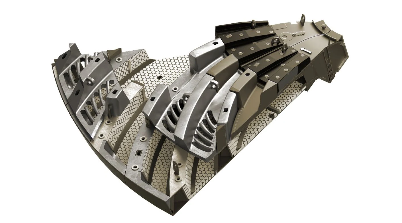
Pulp lifters receive slurry passing through the grates and direct it toward the discharge trunnion. ANRANST provides equipment identification, flow-path and orientation checks, material assessment, quality control and supply of complete sets.
Part Function Position Identification Inner lifter, outer lifter, sector and position number Flow-Path Identification Mill rotation, inlet, outlet and channel direction Structural Interfaces Grate backs, trunnion, hole patterns, clearances and seating Complete Sets Lifters, grates, fasteners, seals, identification marks and layout drawings
Receive slurry behind the grates and direct it toward the discharge trunnion
Pulp lifters use radial or combined channels to direct slurry from behind the grates toward the mill center. Channel volume, direction, inner and outer geometry and interfaces affect discharge performance and flowback.
Similar shapes do not establish interchangeability. Mill rotation, discharge-end diameter, inner or outer location, radial position, grate interface, central opening and mounting holes all determine part identity.
Position and Performance
Flow Capacity, Erosion Resistance and Structural Reliability
Flow velocity, erosion, buildup and loading may differ between inner and outer lifters and between sectors. Record conditions by position.
Grate Inlet Zone
Receives slurry passing through the grates. Check inlet erosion, buildup, plugging and the openings of adjacent grates.
Radial Lifting Channels
Carry slurry as the mill rotates. Check channel volume, direction, wear, flowback and localized deposits.
Central Discharge Outlet
Collects flow toward the trunnion. Check outlet area, transitions, erosion, clearances and the central interface.
Inner-to-Outer Lifter Interfaces
Adjacent faces and channels must form a continuous path. Check position, direction, steps and assembly clearances.
Wear Faces and Ribs
Resist slurry wear and cyclic structural loads. Check plate thickness, welds or cast ribs, cracks and deformation.
Mounting Holes and Backing Surfaces
Provide clamping and support. Inspect hole surrounds, rear seating, looseness, slurry leakage and abnormal wear.
Materials and Manufacturing Processes
Select Materials for Erosion, Abrasion and Structural Design
Material families provide a starting point. Confirm the final grade, properties, construction and manufacturing process against the drawing and operating conditions.
Selection sequence: flow path and position → erosion, wear and structural loads → failure of the current part → material and process → drawing and acceptance requirements.
Failure Diagnosis
Reduced Discharge Can Also Result from Flow-Path or Buildup Problems
Inspect grate openings, lifter channels, the trunnion interface and mill operating conditions together.
| Observed condition | Priority checks | Improvement Options |
|---|---|---|
| Reduced discharge capacity or increased flowback | Channel direction and volume, mill rotation, grate plugging, buildup and trunnion interface | Restore the correct flow direction and effective channel area, and remove restrictions |
| Rapid inlet or outlet erosion | Local velocity, particles, clearances, transition geometry, material and steps between adjacent parts | Improve transitions, erosion-resistant materials and localized protection |
| Channel buildup or plugging | Channel section, dead zones, direction, slurry, particles, wear deformation and deposits formed during shutdown | Remove dead zones and restore the design section and access for cleaning |
| Cracked ribs or deformed assemblies | Structural loads, section size, weld or casting defects, support, material and abnormal impact | Improve structural continuity and toughness, and strengthen non-destructive inspection |
| Looseness, slurry leakage or uneven wear on adjacent parts | Hole patterns, grip length, seating, seals, position numbers, orientation and installation sequence | Restore lifters, grates, fasteners and seals as a complete system |
Drawings and Inquiry Details
Identify Lifters by Position, Direction, Flow Path and Drawing Revision
Use the part or drawing for the specific installation position. Provide an drawing or spare model details when available.
Equipment identification
OEM, series, complete model, serial number, shell diameter, EGL, rotation direction, discharge arrangement and modification history.
Position and Direction
Inner or outer lifter, sector, position number, rotation direction, inlet, outlet, quantity and layout drawing.
Drawing and Revision
drawing, spare model details, drawing revision, project number and markings on the part.
Channel Dimensions
Inlet, outlet, channel width and depth, radial length, central opening, transitions and volume.
Structural Interfaces
Inner and outer diameters, sector, plate thickness, ribs, hole locations, grates, trunnion, seating, seals and weight.
Materials and Operating Conditions
Current material, construction, service life, slurry, particles, throughput, plugging, erosion and failure photographs.
Related Equipment and Parts
Pulp Lifters, Grates, Trunnions, OEM Equipment and Materials
General pages explain discharge functions and materials; OEM pages identify equipment series. Drawings and flow paths complete the technical assessment.
Discharge Grate Check openings, sectors and rear channels upstream of the lifter inlet. Discharge Trunnion Liner Check the central passage and interface downstream of the lifter outlet. General Ball Mills Information Explore grate-discharge systems and part positions. Metso Ball Mills Start with the Select / Premier model and discharge configuration. FLS Ball Mills Identify drawing from the brand, equipment series and installed-machine details. Wear-Resistant Alloy Steel Explore material properties, structural manufacturing and acceptance requirements.