
BALL MILL TRUNNION LINER
Ball Mill Trunnion Liners
Bore protection at the feed or discharge end · Identify separately from the trunnion and bearing liner
Trunnion liners separate process material from the trunnion bore and interface with feeders, pulp lifters or trommels. ANRANST provides installation identification, dimension and drawing checks, material assessment, quality control and manufacture to drawing.
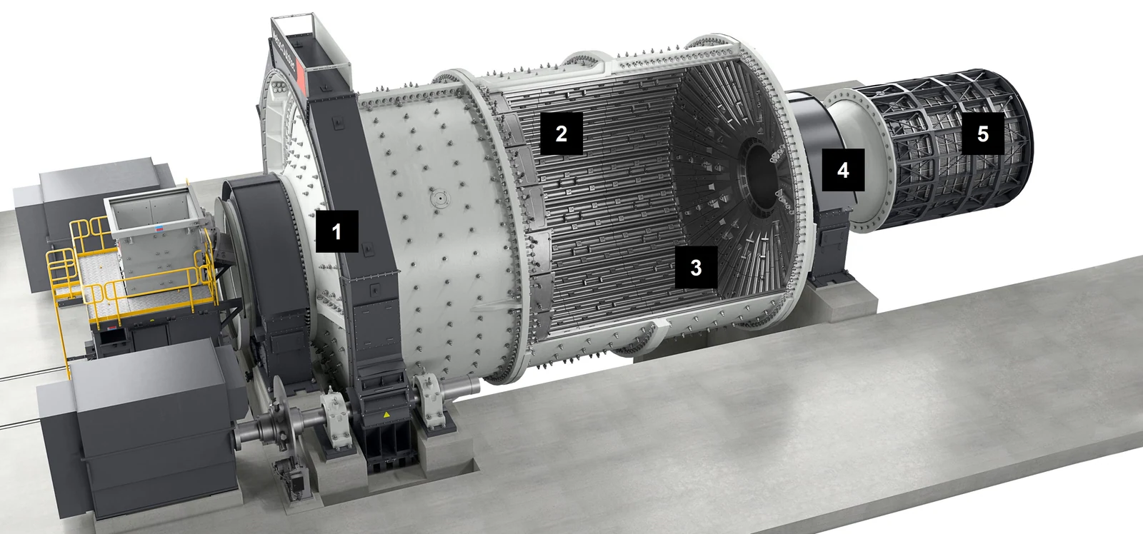
Part scope Feed-end liner Interfaces with the feeder, feed pipe or spiral arrangement Discharge-end liner Interfaces with pulp lifters, discharge passages or the trommel Trunnion body Load-bearing structural component, distinct from the liner Main bearings and bearing liners Support the journal; identify through the bearing system
The liner protects the bore; the trunnion carries loads and the main bearing supports the journal
Trunnion liners directly contact feed, slurry or discharge inside the bore. The load-bearing trunnion includes the journal and transfers shell loads, while the main bearing or bearing liner supports that journal. Each requires different materials, dimensions and acceptance checks.
Feed and discharge ends on one mill may have different designs. Establish end position, discharge arrangement, adjacent interfaces and drawing revision before checking the liner.
Position and Performance
Check flow passages, wear resistance, seating and fastening as one system
Material-entry direction, erosion zones, attachment methods and adjacent interfaces vary by end and design. Record each requirement.
Inlet or outlet transition
Connects to the feeder or discharge assembly. Check abrupt profile changes, erosion, buildup and steps at interfaces.
Internal working surface
Directly contacts ore, slurry or grinding media. Check wall thickness, wear distribution and flow direction.
Flanges and end faces
Connect to adjacent equipment or trommels. Check face runout, seating, seals and flange hole patterns.
Retaining rings and fastening areas
Locate and clamp the liner. Inspect areas around holes, preload, loosening and fastener fractures.
Liner-to-trunnion mating surface
Controls concentricity, support and load distribution. Check clearances, grout or bonding layers, wear and axial movement.
Spirals, dams or inspection ports
Check only where fitted. Confirm function and orientation against drawings and mill rotation direction.
Materials and Structures
Establish liner structure before selecting the supporting body and working surface
Manufacturer designs include one-piece liners, replaceable sleeves and bolted wear elements. Confirm the arrangement against installation drawings, process material and maintenance conditions.
Material families support initial selection. Establish grade, composition, heat treatment, rubber compound, hardness, dimensions and inspection standards through drawings and technical agreements.
Failure Diagnosis
Inspect fit and fastening together with local wear-through, loosening and leakage
Increasing working-surface hardness alone does not correct fretting, concentrated loads or fastening failures.
| Observed condition | Priority checks | Improvement Options |
|---|---|---|
| Rapid bore-wall thinning or local wear-through | End position, flow direction, particles, erosion zones, existing material, wall thickness and profile | Adjust materials, thickness and transition profiles by wear zone |
| Liner loosening, axial movement or abnormal noise | Fit, retaining rings, fasteners, grout or bonding layer, concentricity and support | Restore fit and load distribution, and check the complete retention system |
| Repeated fastener fractures | Hole pattern, preload, liner segmentation, local loads, rear seating and wear | Optimise segmentation and fastener loading, and repair mating surfaces |
| Slurry leakage or trunnion bore damage | Liner penetration, end-face seals, interfaces, cracks, mating-surface wear and adjacent parts | Restore continuous protection, sealing and trunnion bore condition |
| Difficult removal or obstructed bearing maintenance | Segmentation, retaining rings, jacking holes, corrosion, deformation and maintenance space | Use maintainable split structures and removal features within the drawing's permitted design limits |
Drawings and Inquiry Details
Identify trunnion liners by end position, structure, key dimensions and drawing revision
Provide the drawing, sample, model details or customer drawing for the installation position, and confirm the revision.
Equipment identification
OEM, series, full model, serial number, shell diameter, EGL, feed/discharge arrangement and modifications.
End position and structure
Feed or discharge end, one-piece liner, replaceable sleeve, segmented wear elements, quantity and position numbers.
Drawing and Revision
drawing, spare model details, drawing revision, project number and markings on the part.
Key dimensions
Inside and outside diameters, overall length, wall thickness, taper or transition, flange outside diameter, end face and weight.
Hole patterns and adjacent interfaces
Hole diameters and spacing, bolt circle, retaining rings, feeder, pulp lifters, trommel, seals and jacking holes.
Materials and failures
Supporting body and working-layer materials, service life, feed, slurry, wear map, fractures, loosening, leakage and repair history.
Related Equipment and Parts
Connect trunnion liners with adjacent discharge parts, equipment, OEM references and materials
General pages explain part boundaries and materials; OEM pages identify the installed series. Complete technical checks with drawing and key dimensions.
Pulp Lifters Check flow passages and the central interface upstream of the discharge-end liner. Main Bearings, Bearing Liners and Housings Distinguish internal trunnion bore protection from the external journal support system. General Ball Mills Information Review feed and discharge ends, liners and the drive system. Metso Ball Mills Identify Select / Premier models using installation information. FLS Ball Mills Identify drawing from the brand, equipment series and installed-machine details. Rubber and Elastomer Composite Materials Review liner working layers, bonding and duty requirements.