
BALL MILL LIFTER BAR / LIFTER PLATE
Ball Mill Lifter Bars and Plates
Control charge lifting and trajectory · Identify by profile, orientation and position
Lifter bars or plates sit between the shell liners and directly influence lifting, cataracting and cascading of the balls and material. ANRANST provides installation identification, profile checks, material assessment, quality control and complete-set delivery.
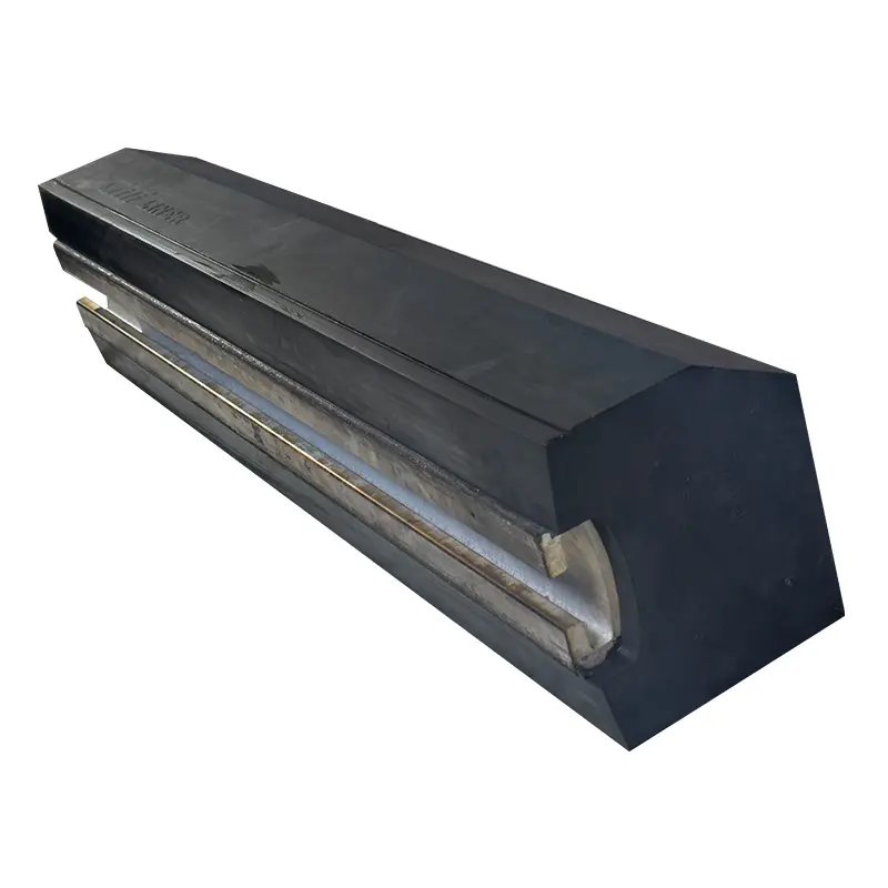
Part Function Layout identification Row count, ring count, position numbers, orientation and quantities per set Lifter profile Height, angle, top width, working face and worn profile Base interface Base curvature, cross-section, hole locations, reinforcement and seating Assembly relationships Lifters, shell plates, bolts, washers and seals
Maintain the designed lifting profile to control charge motion
Lifter height, face angle, top width and spacing influence ball and material movement. The remaining worn profile directly affects lifting capacity, impact location and usable mill volume.
Equal length does not establish interchangeability. Shell diameter, layout, row position, rotation direction, cross-section, base curvature, hole pattern, metal reinforcement and adjacent liners all affect part identification.
Profile and performance
Different surfaces carry different loads and failure risks
Lifter design must address charge motion, profile retention, structural support and reliable fastening together.
Lifter working face
Directly lifts balls and material. Check sliding abrasion, impact, changes in face angle and local breakage.
Top profile
Determines the remaining lifting height. Check rounding, the rate of height loss and whether the worn profile still provides the designed trajectory.
Back and base
Carry structural loads and seat against the shell or liner. Check continuity of support, deformation, cracks and looseness.
Bolt and reinforcement areas
Metal reinforcement, inserts and fastening positions determine load transfer. Inspect for debonding, pull-out, damage around holes and corrosion.
End transitions
Near the feed end, discharge end or adjacent shaped parts, confirm the end profile and length for the specific position.
Interfaces with adjacent liners
Gaps, steps and orientation influence material flow and uneven wear. Check the complete layout during installation.
Materials and Manufacturing Processes
Select materials for impact duty, profile retention and structural design
Material families support preliminary engineering selection. Confirm the final grade, properties, reinforcement and bonding method against drawings and operating conditions.
Selection sequence: lifter position and profile → impact and wear → failure of existing parts → material and structure → drawings, manufacturing and acceptance requirements.
Failure Diagnosis
Assess lifting performance, service life and structural reliability together
Selecting solely for abrasion resistance can trade height loss for fracture, debonding or fastening failure.
| Observed condition | Priority checks | Improvement Options |
|---|---|---|
| Premature lifter height loss or rounding | Profile, spacing, speed, charge filling, balls, feed, material and wear pattern | Improve profile retention while maintaining toughness and structural integrity |
| Metal lifter plate fracture or breakage | Impact, abrupt section changes, rear support, hole positions, preload, hardness and manufacturing defects | Improve toughness and continuous support, and strengthen non-destructive inspection |
| Rubber tearing or cutting | Sharp feed, inserts, edge restraint, temperature, media size and foreign objects | Optimise the rubber compound, edge design and reinforcement protection |
| Reinforcement debonding or insert pull-out | Bonding process, reinforcement surface, insert positions, load path, deformation and corrosion | Improve reinforcement and bond quality, and verify pull-out resistance |
| Loosening or uneven wear of adjacent parts | Hole pattern, grip length, preload, base seating, orientation, clearances and installation sequence | Restore the complete layout, seating and fastening system |
Drawings and Inquiry Details
Identify lifters by position, orientation, profile and drawing revision
Provide the drawing, sample, spare model details or customer drawing for the specific position, with its revision.
Equipment identification
OEM, series, full model, serial number, shell diameter, EGL, rotation direction and modifications.
Layout and positions
Layout drawing, number of rows, position numbers, orientation, quantity per circumferential row, adjacent plates and complete BOM.
Drawing and Revision
drawing, spare model details, drawing revision, project number and markings on the part.
Key dimensions
Length, overall height, face angle, top width, base width, base curvature, hole positions and weight.
Structure and fastening
Metal or rubber composite construction, reinforcement, inserts, bolt head shape, grip length and seating.
Materials and Operating Conditions
Existing material, hardness or elastomer compound, service life, remaining height, balls, speed, charge filling and failure photographs.
Related Equipment and Parts
Connect lifters with shell liners, equipment, OEM references and materials
Start with duty and material requirements, identify the OEM installation, then complete the technical checks using position numbers, drawing and drawings.
Ball Mill Shell Liners Check adjacent liners, layout, steps and fastening interfaces. Ball Mill Lining System Review adjacent parts such as end liners, discharge components and trunnion liners. General Ball Mills Information Review machine layout, equipment type and part positions. Metso Ball Mills Identify Select / Premier models using their principal dimensions. FLS Ball Mills Identify drawing from the brand, equipment series and installed-machine details. Rubber and Polyurethane Materials Review elastomers, composite structures and acceptance requirements.