
01
بطانات الأسطوانة
بطانات الأسطوانة / ألواح الأسطوانة
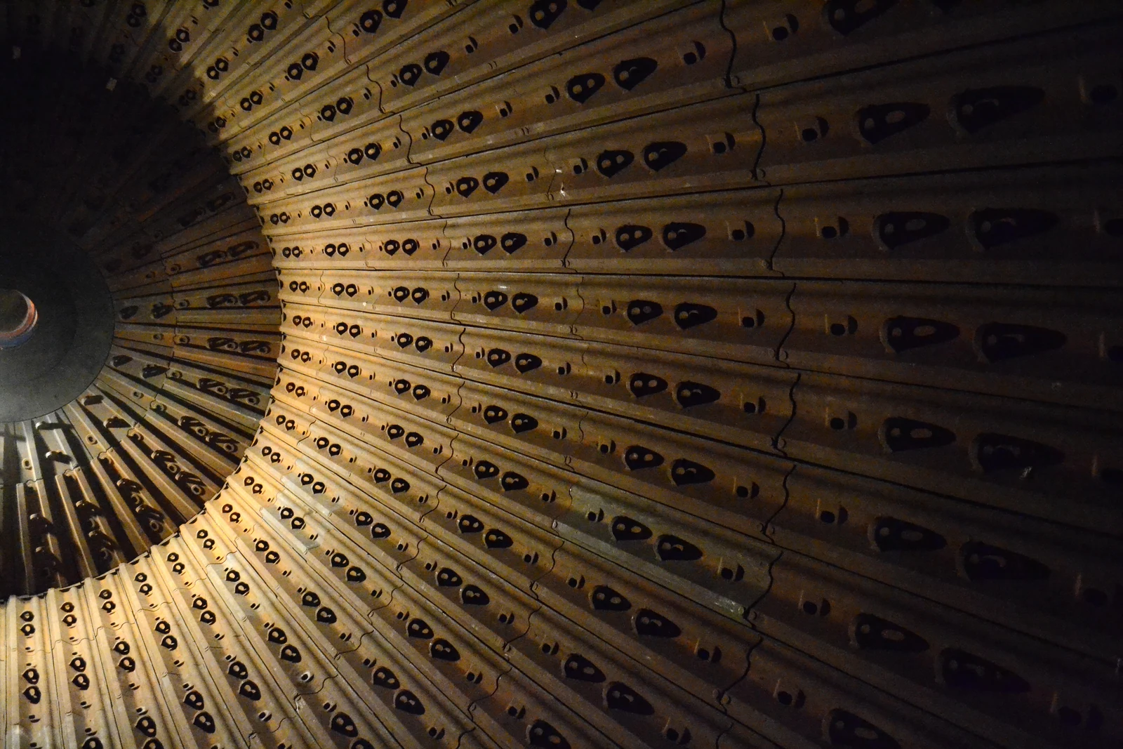
تحمي بطانات الأسطوانة داخلها وتضبط حركة أوساط الطحن. افحص قطر المطحنة وطول الأسطوانة والتخطيط وتوزيع الثقوب والسماكة ووزن كل قطعة وطريقة التثبيت. توضح الصورة فئة عامة من الأجزاء.
حدد تركيبات سلسلة FT وFuller-Traylor، ثم راجع بطانات المطاحن الكروية وأجزاء تآكل التفريغ والتروس الحلقية والتروس الصغيرة ومحاور الدوران والمحامل الرئيسية وقطع غيار التزييت الهيدروليكي. تنسق ANRANST التصنيع المستند إلى الرسومات في الصين وضبط الجودة وتسليم القطع النهائية.
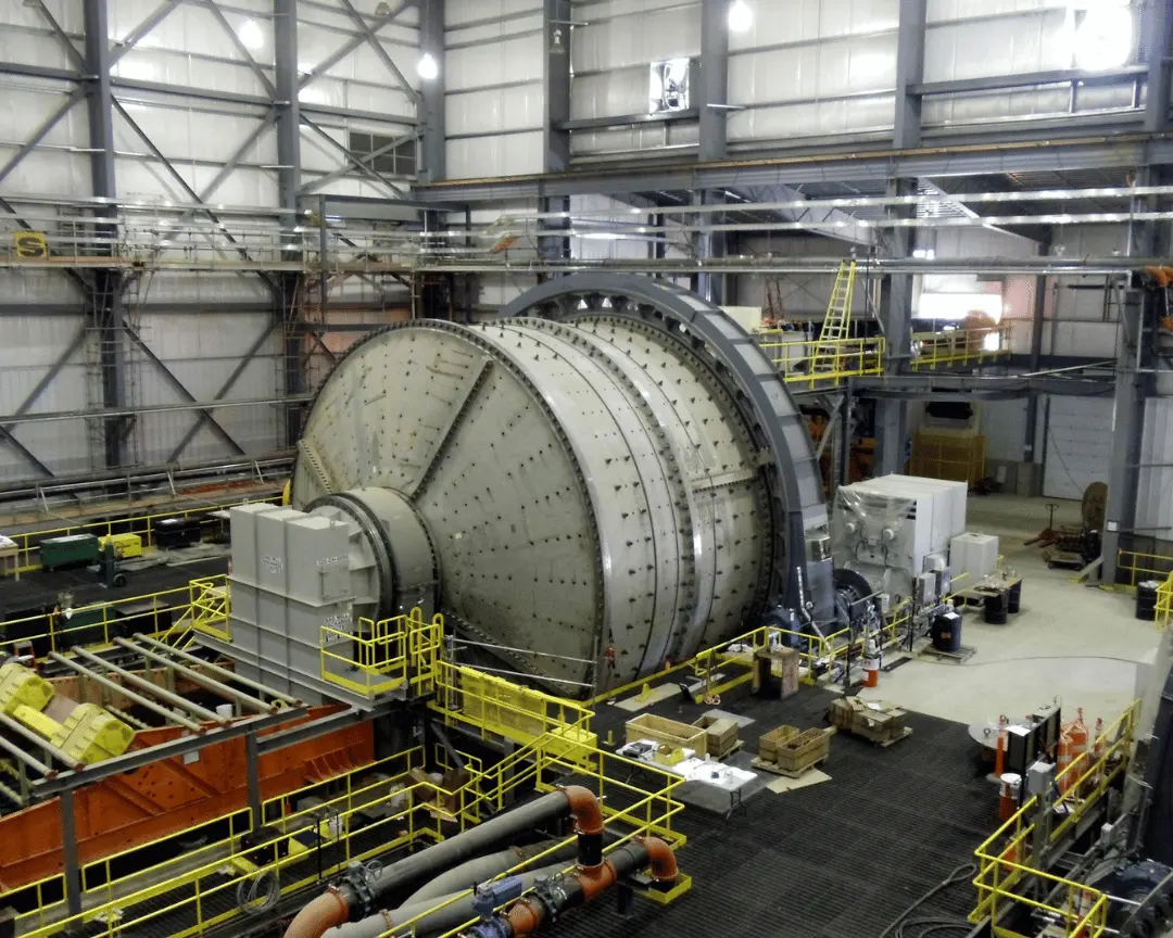
تغطي هذه الصفحة المعلومات ذات الصلة بتحديد قطع الغيار وتوريدها: الأقطار القياسية لسلسلة FT والنطاق الإجمالي الحالي للمطاحن الكروية Fuller-Traylor وتجهيزات الدعم ونظام الإدارة وأجزاء التآكل وقطع الغيار الرئيسية التي تساعد ANRANST في توفيرها.
تدرج فقط السلاسل والأقطار ونطاقات القدرة القابلة للمراجعة على موقع FLS الحالي. افحص المواصفات الكاملة للمطاحن الخاصة بالمشروعات بمقارنتها بلوحة البيانات والرقم التسلسلي ورسم الترتيب العام وسجلات المعدة.
| سلسلة / التكوين | الأبعاد الرئيسية والقدرة | ملاحظات التفريغ وتحديد المعدة |
|---|---|---|
| سلسلة FT — مطحنة كروية | القطر القياسي 1.6–4.3 m | رطب أو جاف؛ تفريغ بالفيض عبر محور الدوران أو عبر شبكة تصريف أو تفريغ محيطي أو بتيار الهواء |
| مطحنة كروية Fuller-Traylor | القطر 1.6–8.5 m؛ القدرة حتى 22,000 kW | سلسلة خاصة بالمشروع؛ حددها بلوحة البيانات ورسم الترتيب العام والرقم التسلسلي وتجهيز نظام الإدارة |
| مطحنة كروية بتفريغ بالفيض Fuller-Traylor | ضمن نطاق المطاحن الكروية الحالي 1.6–8.5 m | تفريغ بالفيض؛ افحص طول الأسطوانة والقدرة وترتيب الدعم بمقارنتها بوثائق المشروع |
| مطحنة كروية بتفريغ شبكي Fuller-Traylor | ضمن نطاق المطاحن الكروية الحالي 1.6–8.5 m | تفريغ شبكي؛ افحص شبكات التصريف وروافع الملاط وبنية طرف التفريغ |
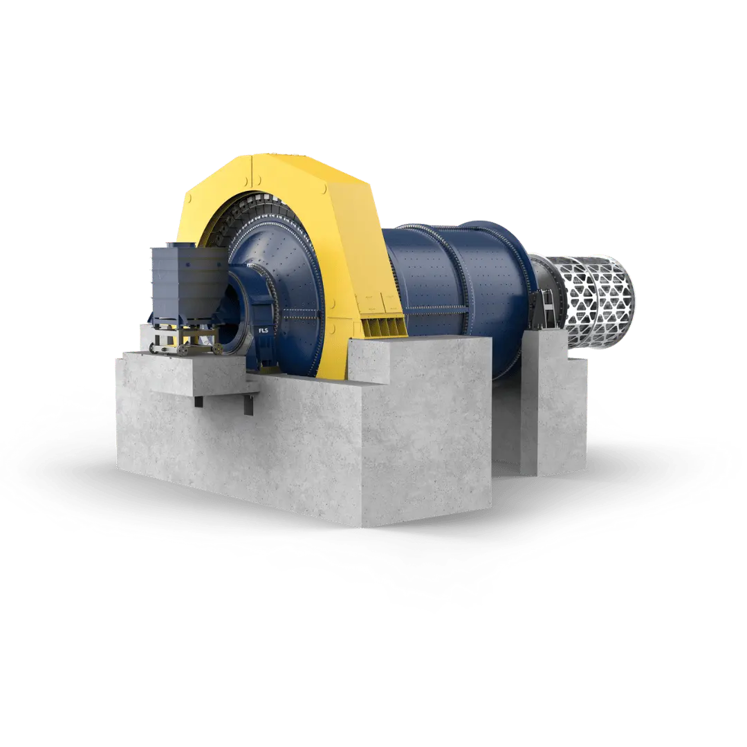
تتطابق الأرقام على المخطط مع الصفوف أدناه.
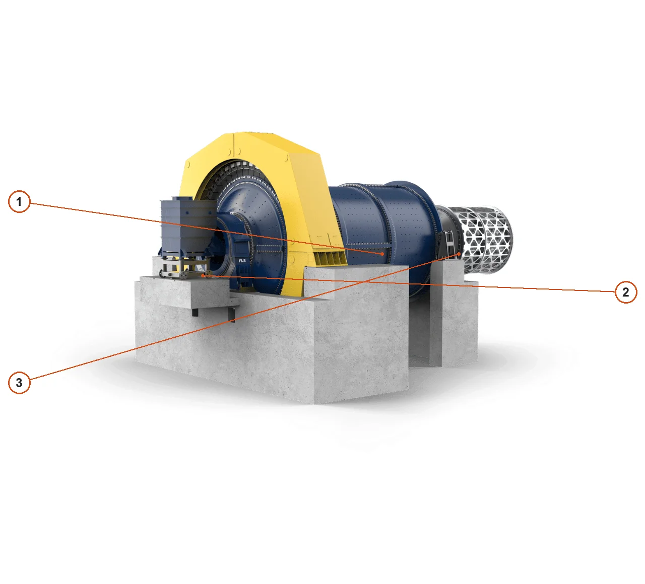
| الرقم | المكوّن | الموضع | ينطبق على |
|---|---|---|---|
| 1 | جسم المطحنة | الجسم الدوار بين دعامات النهايتين | إصدار التصميم المعروض من OEM; قد تختلف التجهيزات الأخرى |
| 2 | مزلق التغذية | مدخل التغذية في الأمام يسارا | إصدار التصميم المعروض من OEM; قد تختلف التجهيزات الأخرى |
| 3 | غربال أسطواني للتفريغ | طرف التفريغ على اليمين | إصدار التصميم المعروض من OEM; قد تختلف التجهيزات الأخرى |
يشمل نطاق بطانات المطاحن الأفقية FLS ARMOUR® الحالي حلولا فولاذية ومطاطية ومركبة. اختر المادة لكل موضع حسب الصدمات والكشط وحت الملاط والوزن وأهداف الصيانة.
بطانات الأسطوانة / ألواح الأسطوانة
تحمي بطانات الأسطوانة داخلها وتضبط حركة أوساط الطحن. افحص قطر المطحنة وطول الأسطوانة والتخطيط وتوزيع الثقوب والسماكة ووزن كل قطعة وطريقة التثبيت. توضح الصورة فئة عامة من الأجزاء.
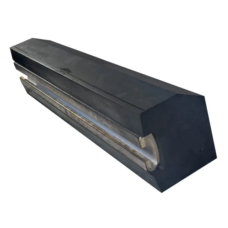
قضبان الرفع / ألواح الرفع
تعمل قضبان الرفع مع بطانات الأسطوانة لضبط مسارات الرفع وتحمل الصدمات والكشط المتكررين. افحص المقطع وارتفاع الرفع وزاوية التخطيط واتجاه التآكل وبنية الوصلات. توضح الصورة فئة عامة من الأجزاء.
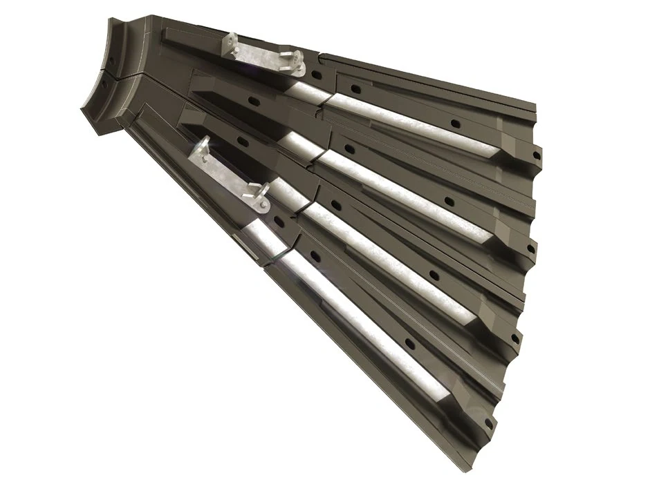
بطانات الرأس / الطرف
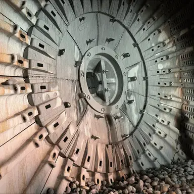
تركب بطانات الأطراف داخل رأس التغذية أو التفريغ وتتحمل صدمات الكرات والخام والملاط. ميز بين طرفي التغذية والتفريغ والحلقات الداخلية والخارجية وتوزيع الثقوب والأشكال والعلاقات مع البطانات المجاورة. توضح الصورة فئة عامة من الأجزاء.
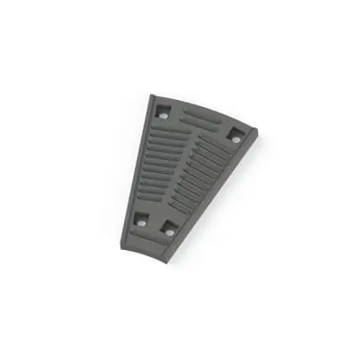
شبكات التصريف
تسمح الشبكات بمرور الملاط مع احتجاز أوساط الطحن في المطاحن ذات التفريغ الشبكي. افحص نوع الشبكة وأبعاد الفتحات ومجاري التدفق وموضع الطرف والتخطيط ومتطلبات منع الانسداد. توضح الصورة فئة عامة من الأجزاء.
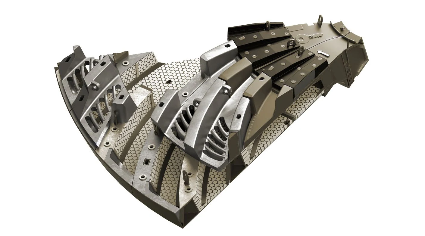
روافع الملاط / روافع التفريغ (ليفتر)
تقع روافع الملاط خلف شبكات التصريف وتوجه الملاط إلى محور دوران التفريغ. افحص اتجاه التدفق والروافع الداخلية والخارجية وموضع الطرف والثقوب وواجهات الشبكة. توضح الصورة فئة عامة من الأجزاء.
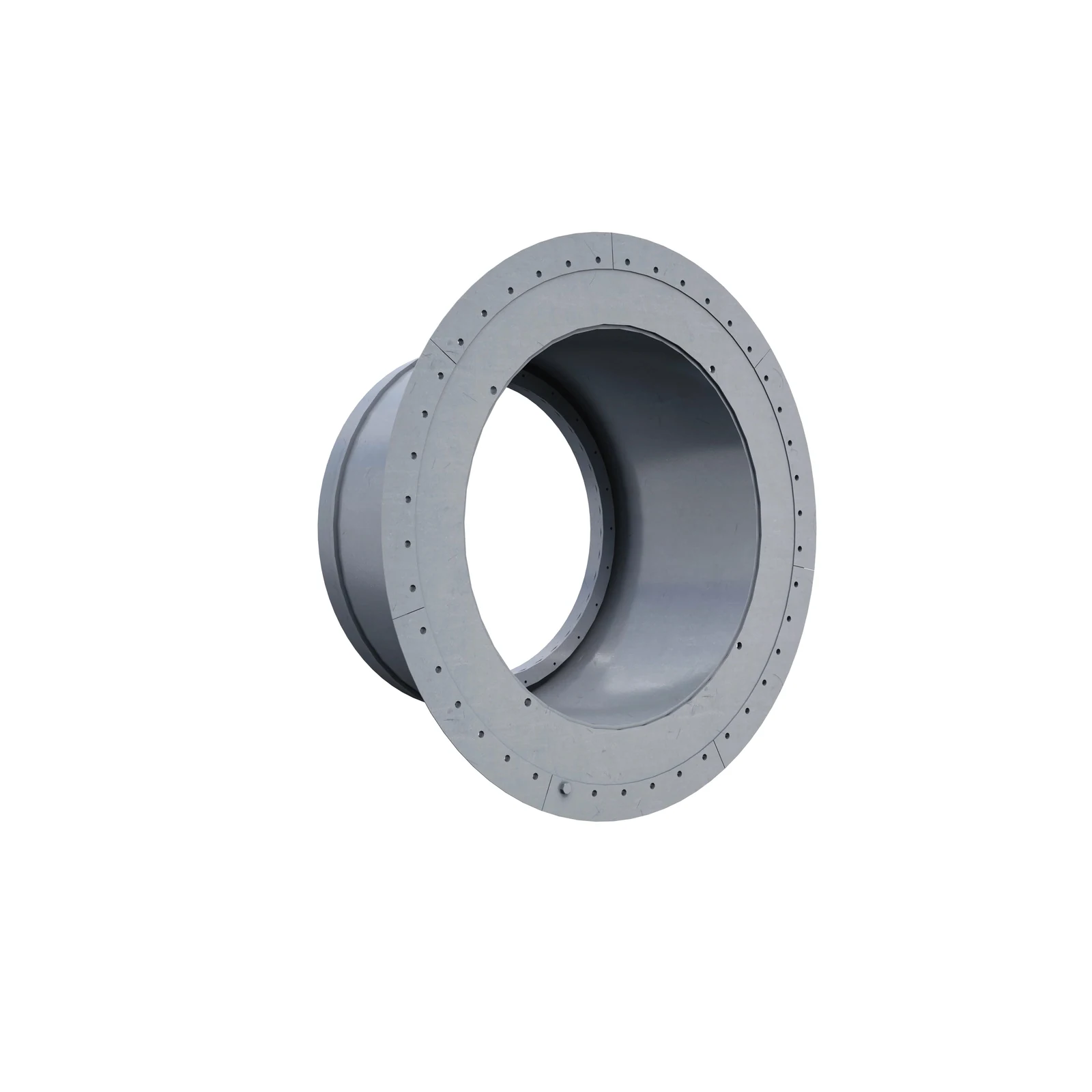
بطانات محاور دوران المطحنة
تركب بطانات محور الدوران داخل ثقبه عند التغذية أو التفريغ، فتحميه وتشكل مجرى المادة. افحص موضع الطرف والشكل الداخلي والطول وتوزيع ثقوب الشفة والأختام وبنية الوصلات. توضح الصورة فئة عامة من الأجزاء.
يشمل نطاق قطع غيار المطاحن العام الحالي لدى FLS التروس الحلقية ومحاور الدوران والأختام والمكونات الهيدروليكية والمرشحات والحساسات. توفر هذه الصفحة أيضا تحديد المحامل الرئيسية ورؤوس المطاحن وأنظمة الإدارة وعناصر التثبيت الحرجة بالاستناد إلى الرسومات.
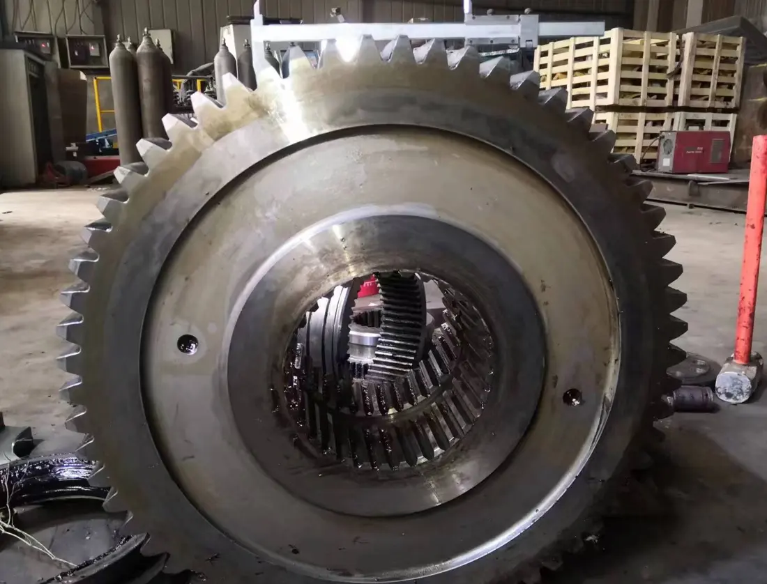
ترس حلقي / ترس حلقي
مكون رئيسي لنقل الحركة في المطاحن الكروية المدارة بالتروس. افحص الموديول وعدد الأسنان وزاوية الضغط وعرض وجه الأسنان والبنية المقسمة والمسافة بين المركزين واتجاه الحلزون وعلامات التطابق ومتطلبات المعالجة الحرارية.
عرض تفاصيل الجزء →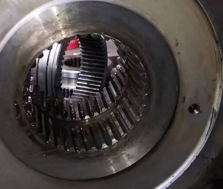
ترس صغير (بينيون) للإدارة
افحص الترس الصغير مع الترس الحلقي. افحص هندسة الأسنان ومواضع الارتكاز ومقاعد المحامل ومجاري الخوابير أو الوصلات ودقة الأسنان والمعالجة الحرارية واتجاه التعشيق.
عرض تفاصيل الجزء →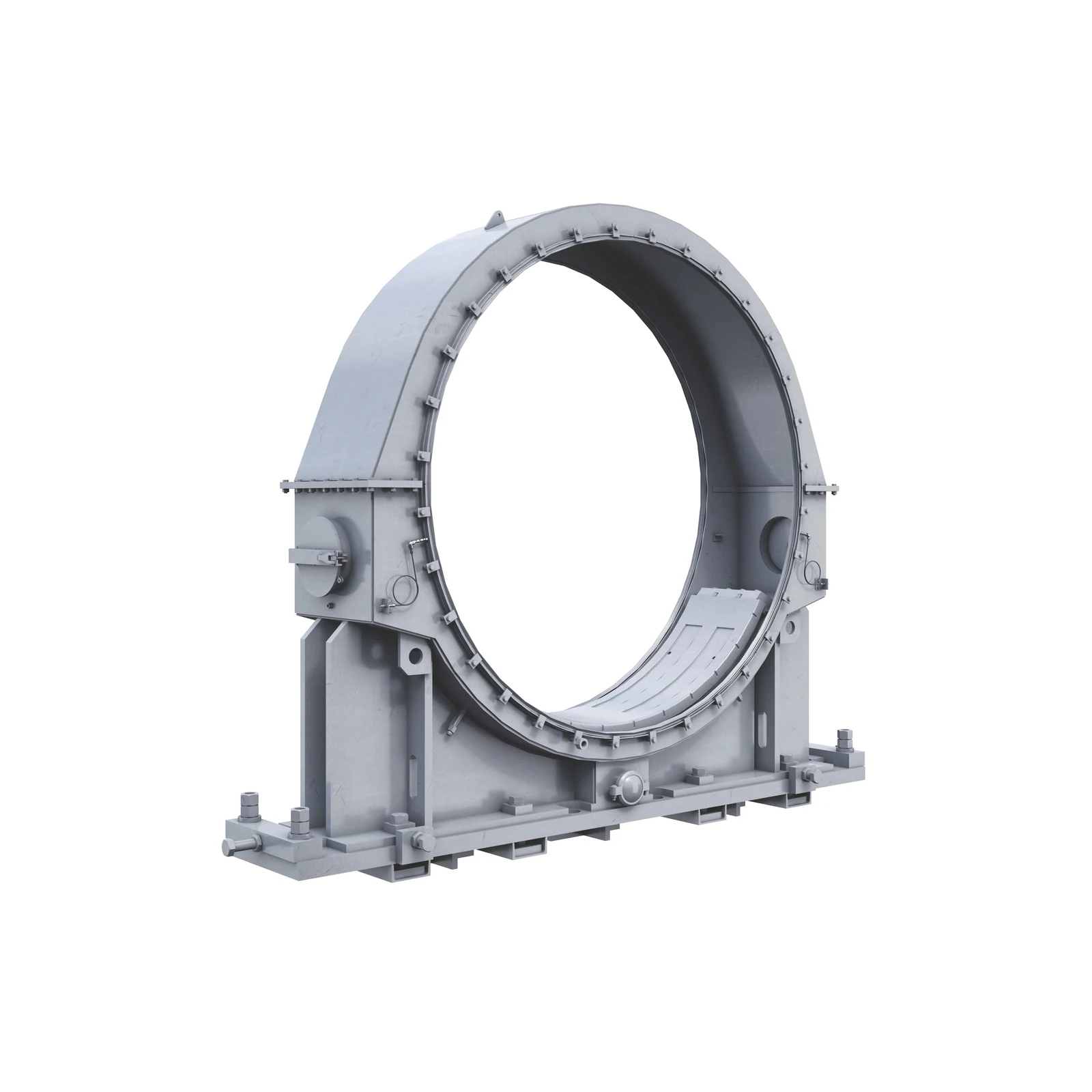
المحامل الرئيسية والجلب & الأغلفة
تسند هذه المكونات محاور الدوران والمجموعة الدوارة. افحص قطر موضع الارتكاز والطرف الثابت أو العائم والتصميم الهيدروستاتيكي أو الهيدروديناميكي ومادة بطانة المحمل ومجاري الزيت والأختام وارتفاع التركيب. توضح الصورة فئة عامة من الأجزاء.
عرض تفاصيل القطعة العامة ←محور الدوران & رأس المطحنة
تصل هذه الهياكل الكبيرة الحاملة للأحمال الأسطوانة بالمحامل الرئيسية ومجاري التغذية والتفريغ. افحص موضع الطرف ومواضع الارتكاز وتوزيع ثقوب الشفة والمواد والفحوص غير الإتلافية ومراجع التشغيل الميكانيكي وواجهات البطانات. تعرض الصورة بنية مطحنة FLS الكروية.
قدم الرسومات للمطابقة الفنية →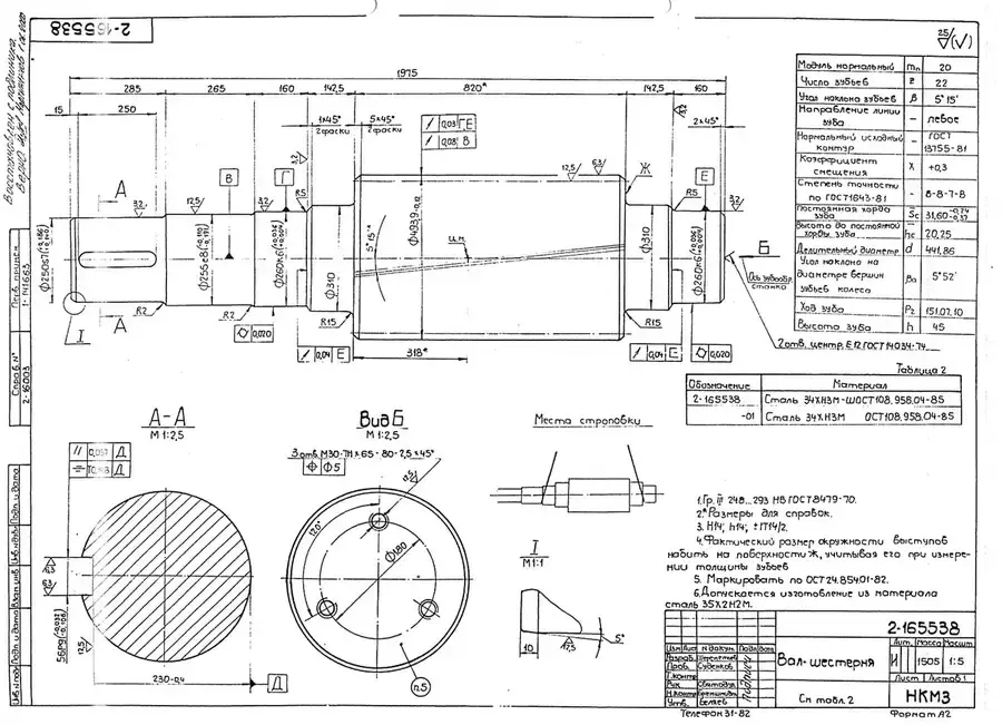
مجموعة نقل الحركة & الوصلات
تشمل محركات عالية السرعة مع مخفضات سرعة أو محركات منخفضة السرعة موصولة مباشرة بالتروس الصغيرة أو واجهات أنظمة الإدارة بدون تروس. افحص القدرة والسرعة ونسبة التخفيض والوصلة والكبح ومراجع التركيب. توضح الصورة أجزاء عامة لنظام إدارة المطاحن الأفقية.
قدم الرسومات للمطابقة الفنية →
الأختام والهيدروليك & أجزاء التزييت
يشمل نطاق قطع غيار المطاحن الحالي لدى FLS الأختام والمكونات الهيدروليكية ومرشحات الزيت والحساسات. قارن بمخططات الأنظمة المحددة والواجهات والضغط والسائل وعلامات القطعة الأصلية. توضح الصورة فئة الأختام الهيدروليكية فقط.
قدم الرسومات للمطابقة الفنية →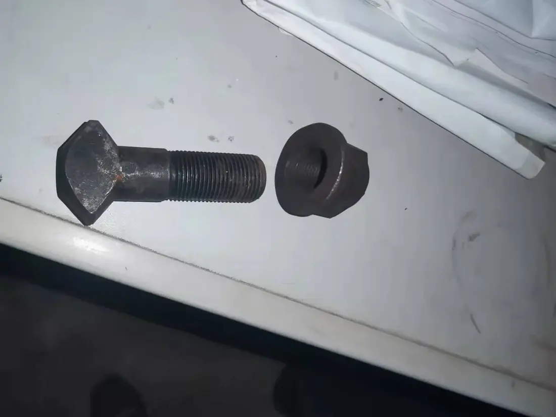
المسامير الملولبة الحرجة & لوازم التثبيت
تصل هذه الأجزاء شفاه الأسطوانة والبطانات والمجموعات الدوارة. افحص مواصفات القلاوظ والطول الفعال ودرجة المادة وطريقة التحميل المسبق وبنية القفل والوردات ومساحة التجميع والفك. تعرض الصورة فئة منتجات عناصر التثبيت لدى ANRANST.
قدم الرسومات للمطابقة الفنية →قدم عائلة سلسلة FT أو Fuller-Traylor والمواصفات الكاملة والرقم التسلسلي وترتيبات الدعم ونظام الإدارة وموضع الجزء والرسومات وصور القطعة الحالية وظروف التشغيل.
لا. افحص أيضا طول الأسطوانة وطرف التغذية أو التفريغ وتخطيط البطانات وتوزيع الثقوب وطريقة التثبيت وبنية التفريغ وإصدار الرسم والواجهات الفعلية.
قدم الرسم ومواصفات المعدة المطابقة والرقم التسلسلي وموضع التركيب وإصدار الرسم ومعلومات القطعة المستعملة. تتيح هذه البيانات المقارنة بقائمة مواد المعدة والأبعاد الإنشائية والتركيب المناسب.
قدم عائلة سلسلة FT أو Fuller-Traylor والقطر والطول وترتيبات نظام الإدارة والدعم ولوحة البيانات والرقم التسلسلي وصور القطعة الحالية والرسومات والمادة وظروف التشغيل. نستخدمها لتحديد الأجزاء وتقييم المواد وتنظيم الإنتاج في مسابك معتمدة وضبط الجودة وتسليم المكونات النهائية.
أو تواصل معنا مباشرة: +86 156 3797 3199
zzx@anranst.com
تقدّم ANRANST لعملائها حول العالم التقييم الهندسي والإنتاج في مسابك معتمدة وفق المتطلبات الفنية للعميل ومراقبة الجودة وتسليم القطع الجاهزة لقطع التآكل المخصّصة وقطع الغيار الصناعية، مع إمكانية دعم قطع صناعية مخصّصة أخرى.
نراجع أسطح التزاوج وأبعاد الوصلات، ونقيّم إمكانية التصنيع من حيث المادة والمعالجة الحرارية.
Material grades and heat-treatment processes are specified order by order, stated in the technical agreement and tracked through production.
تأكيد الرسم، ومراقبة المواد والعمليات، ومتابعة الإنتاج، والفحص، وتنسيق القبول.
ننسّق التصنيع وتأكيد الجودة والتغليف والتسليم للقطع الكاملة ضمن سلسلة توريد متكاملة وعملية.
زوّدنا بالطراز الحالي والرسومات والمواد أو ظروف التشغيل لنتمكن من تحديد المراجعة الفنية ومسار التوريد المناسبين.
أرسل استفساراً