
01
بطانات حلق التغذية
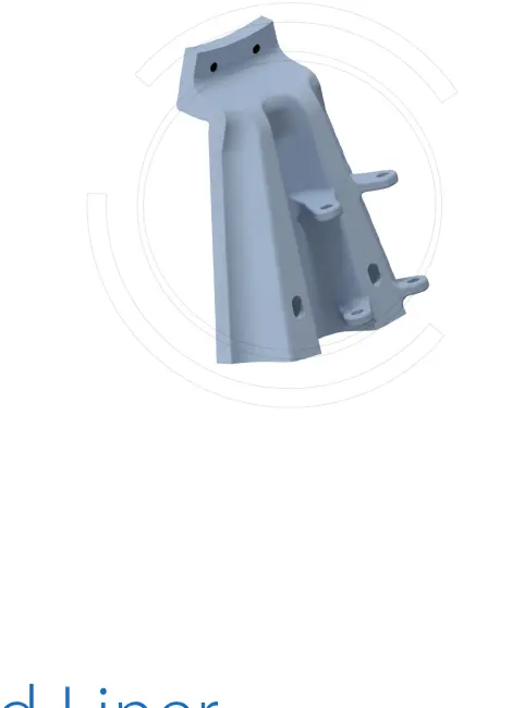
مزلق التغذية / بطانة الحلق
إنها تتحمل التأثير المباشر للخام الخشن والتآكل المنزلق. طابق ملف تعريف المدخل وواجهة الشفة وتوزيع الثقوب والخلوص إلى شلال التغذية.
عرض تفاصيل الجزء →حدد الأجزاء القابلة للتآكل وقطع الغيار من خلال الأبعاد المثبتة والدعم وتكوين الإدارة، ثم قم بمراجعة مواضع الأجزاء والمواد ومتطلبات الرسم والاستعلام في صفحة واحدة.
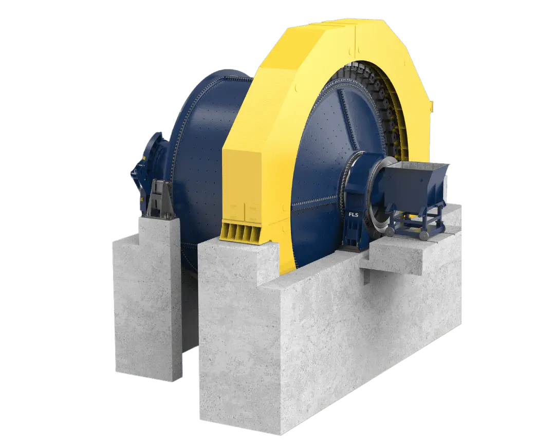
مجموعة المطاحن Fuller-Traylor SAG/AG المنشورة حاليا لها أقطار 4.3–12.2 m وقدرة مثبتة تصل إلى 28,000 kW. يتطلب التعرف على قطع الغيار أيضا الطول الفعلي والرقم التسلسلي ورسم الترتيب العام والدعم وتكوين الإدارة.
يتم تحديد عائلة FLS هذه من خلال أبعاد المشروع وتكوينه. يتم سرد النطاقات المنشورة الرسمية فقط؛ لم يتم اختراع رموز نموذجية مستقلة.
| سلسلة / التكوين | الأبعاد أو المعلمات المنشورة رسميا | فحص تحديد هوية قطع الغيار الرئيسية |
|---|---|---|
| مطحنة شبه ذاتية الطحن (SAG) Fuller-Traylor | القطر 4.3–12.2 m؛ الطاقة المثبتة تصل إلى 28,000 kW؛ شحن الكرة 6–15% | القطر × الطول الفعال، الرقم التسلسلي، اتجاه التغذية/التفريغ، تجزئة البطانة وتكوين الإدارة |
| مطحنة ذاتية الطحن AG Fuller-Traylor | ضمن نفس نطاق قطر 4.3–12.2 m المنشور؛ يستخدم الطحن الذاتي خاما بدون وسائط كروية فولاذية | القطر × الطول الفعال والرقم التسلسلي وطريقة التفريغ ونظام البطانة وهيكل الدعم |
| ترتيب الدعم | مدعومة على مرتكزات الدوران أو على الأسطوانة | رسم الترتيب العام، واجهات الأساس، نوع المحمل والهيكل الحامل للمجلة أو الأسطوانة |
| نوع الإدارة | إدارة بتروس عالية السرعة أو إدارة مباشرة منخفضة السرعة أو بلا تروس؛ قد تستخدم التكوينات ذات التروس ترسا صغيرا واحدا أو ترسين، وتصل القدرة في الأمثلة المنشورة للإدارة بترس صغير واحد إلى 10,000 kW. | واجهات محيط الجسم، أو الترس الصغير، أو عمود الإدارة، أو الوصلة، أو المخفض، أو المحرك الحلقي |
| تكوين التفريغ | طبلة أو شاشة تهتز. أقطار طبلة FLS AG/SAG تصل إلى 6.0 m | شبكات التفريغ، وروافع تفريغ الملاط، ومخروط التفريغ، وواجهات الطبلة واتجاه الدوران |
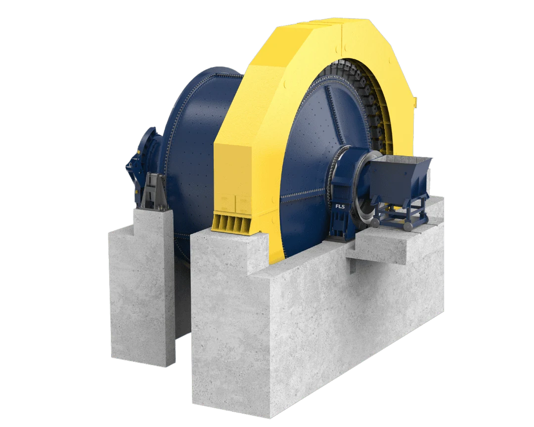
تتطابق الأرقام على المخطط مع الصفوف أدناه.
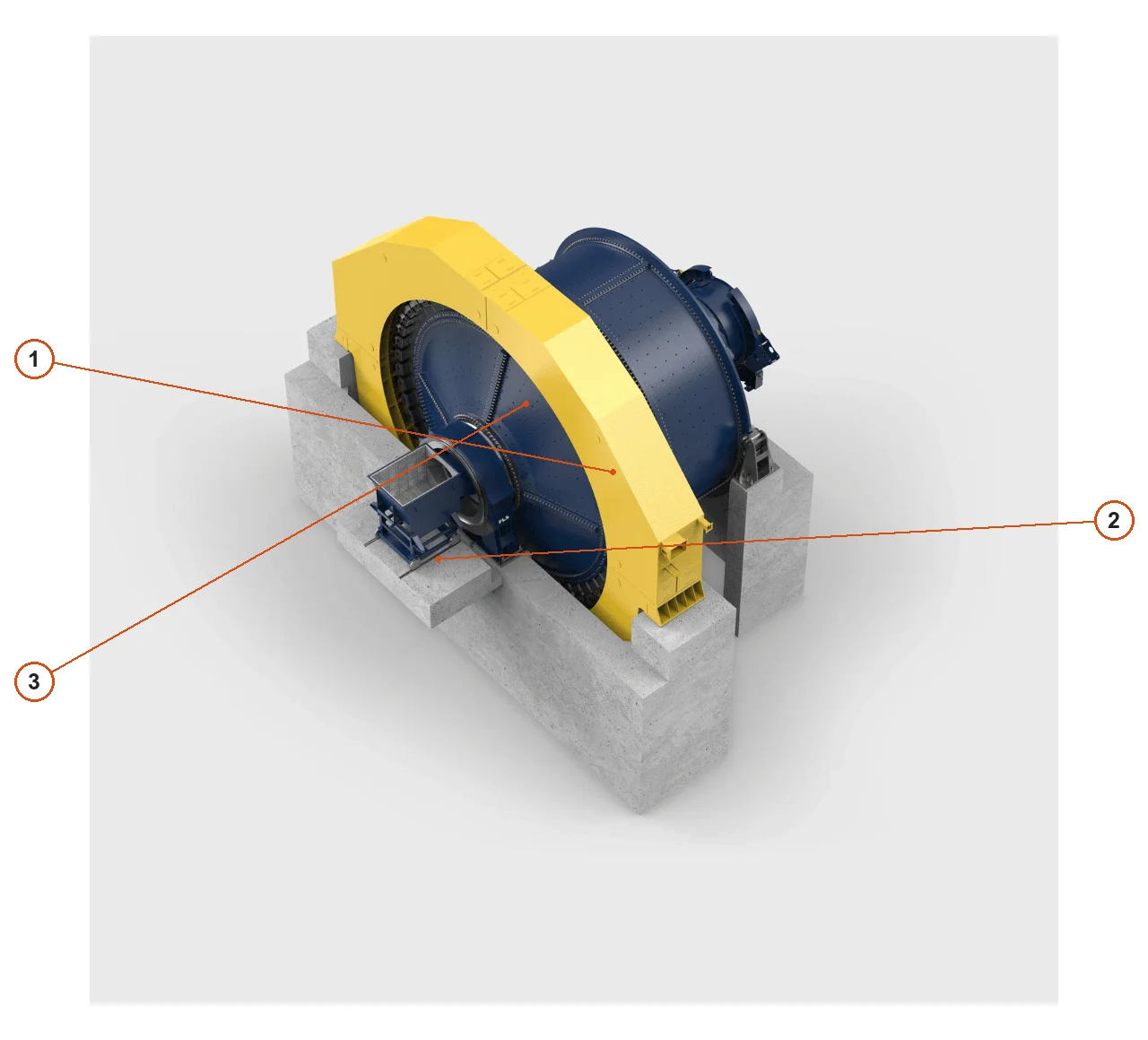
| الرقم | المكوّن | الموضع | ينطبق على |
|---|---|---|---|
| 1 | جسم المطحنة | الجسم الدوار المركزي | إصدار التصميم المعروض من OEM; قد تختلف التجهيزات الأخرى |
| 2 | مزلق التغذية | مدخل التغذية في مقدمة المطحنة المرسومة | إصدار التصميم المعروض من OEM; قد تختلف التجهيزات الأخرى |
| 3 | غطاء حماية نظام الإدارة | واقي الإدارة الأصفر حول الجسم | إصدار التصميم المعروض من OEM; قد تختلف التجهيزات الأخرى |
تختلف الصدمات والتآكل الكاشط والتعرية بالملاط بين مواضع المطحنة نفسها. تبين البطاقات مواضع الأجزاء والمواد المقترحة؛ طابق المتطلبات النهائية مع رسومات التركيب ورسم الجزء وتوزيع الثقوب وظروف التشغيل.
مزلق التغذية / بطانة الحلق
إنها تتحمل التأثير المباشر للخام الخشن والتآكل المنزلق. طابق ملف تعريف المدخل وواجهة الشفة وتوزيع الثقوب والخلوص إلى شلال التغذية.
عرض تفاصيل الجزء →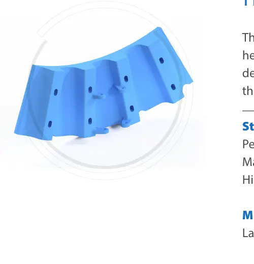
بطانة داخلية للرأس من جهة التغذية
تعمل هذه على حماية الجزء الداخلي من رأس التغذية من تأثير الخام المجمع والتآكل وتآكل الملاط. طابق حدود المقطع وسمكه مقابل رسومات التثبيت.
عرض تفاصيل الجزء →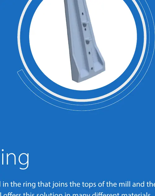
بطانة خارجية للرأس من جهة التغذية
تغطي هذه المناطق عالية التأثير حول حلقة رأس التغذية الخارجية. طابق علاقات التثبيت مع بطانات الرأس الداخلية وبطانات الغلاف والمثبتات.
عرض تفاصيل الجزء →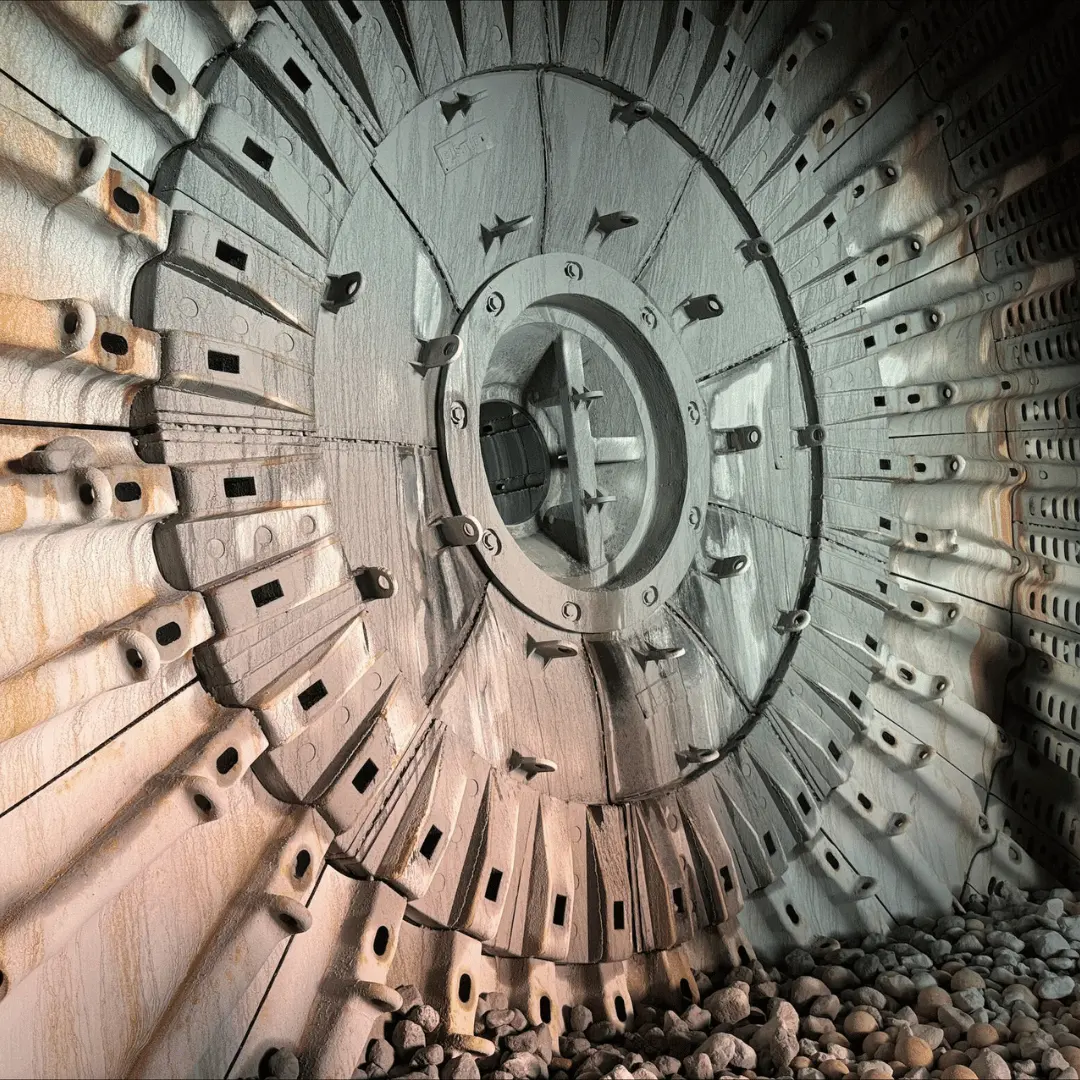
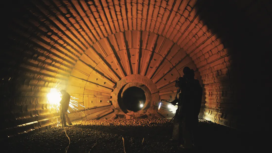
بطانة الأسطوانة & قضيب رفع شحنة الطحن
هذه تتحكم في مسار رفع الشحنة وتحمي الأسطوانة. تؤثر الملامح وارتفاع الرفع والتجزئة وأنماط ثقب المسمار الملولب بشكل مباشر على الطحن وعمر البطانة.
عرض تفاصيل الجزء →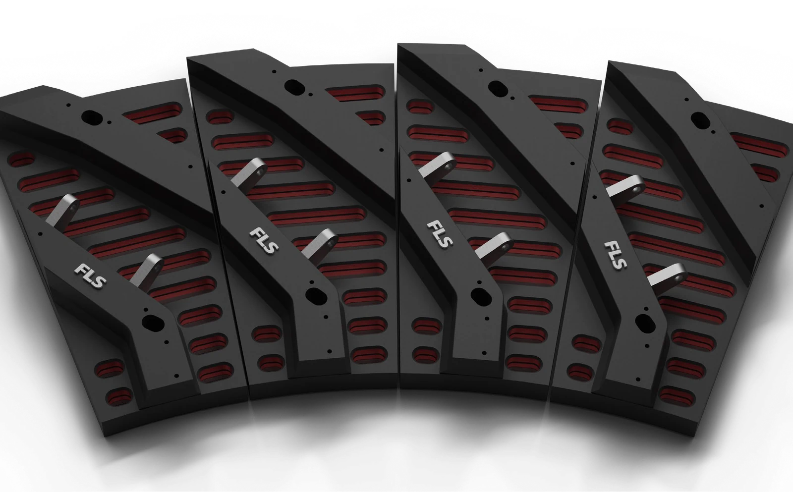
شبكة تصريف
تتحكم الشبكات في ممرات التفريغ وتتحمل تآكل الملاط وتأثير الخام وأحمال الانسداد. يجب أن يكون شكل الفتح والمساحة المفتوحة والدعم الخلفي متوافقين.
عرض تفاصيل الجزء →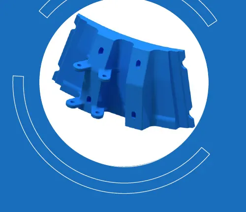
بطانة تفريغ وسيطة
تعمل هذه على توصيل أنظمة الشبكة والبطانة النهائية. طابق الموضع الشعاعي والتداخلات المجاورة واتجاه التثبيت وبدلات التآكل.
عرض تفاصيل الجزء →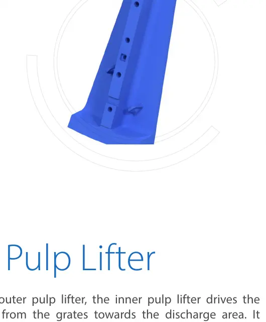
رافع تفريغ خارجي للملاط
توجه هذه الأجزاء الملاط المار عبر الشبكات نحو ممر التفريغ. يجب أن يتوافق المقطع العرضي للتدفق واتجاه الدوران ومواضع الشبكات المجاورة مع تركيب المعدة.
عرض تفاصيل الجزء →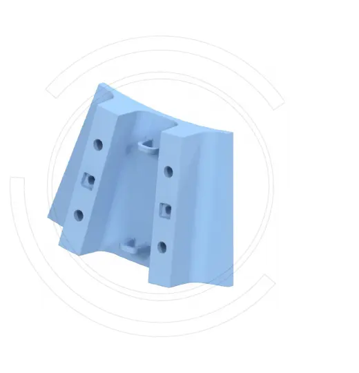
رافع تفريغ داخلي للملاط
تقع داخل نظام التفريغ، وتقوم بنقل الملاط والتحكم في التدفق العكسي. طابق اتجاه التدفق وارتفاع الشفرة وتسلسل التجميع.
عرض تفاصيل الجزء →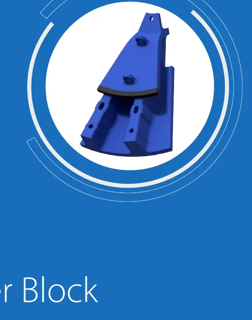
مخروط التفريغ
تقوم هذه الأجهزة بتوصيل روافع تفريغ الملاط بممر مرتكز التفريغ. طابق شكل المخروط والتجزئة وأنماط فتحة الحافة واتجاه التفريغ.
عرض تفاصيل الجزء →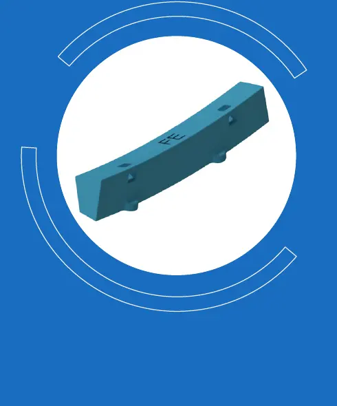
حلقة ملء & بطانة إحكام
تملأ الفجوات وتوفر التوسيد والإحكام داخل نظام البطانات. طابق الانضغاط وشكل الأخدود والسائل وأبعاد الأجزاء المعدنية المجاورة.
عرض تفاصيل الجزء →تتطلب محركات التروس ودعم مرتكز الدوران ودعم الهيكل قطع غيار مختلفة. قم بإنشاء مطابقات فردية بعد استلام الطراز المثبت بالكامل والرقم التسلسلي ورسم الترتيب العام وOEM أو الرسم.
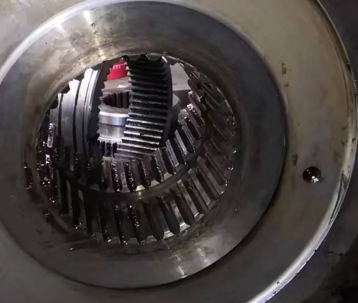
Pinion
للتكوينات ذات الإدارة بالتروس. طابق عدد الأسنان والموديول وزاوية الضغط وزاوية الحلزون ومناطق ارتكاز العمود ودقة الأسنان والمعالجة الحرارية مع الترس المحيطي.
عرض تفاصيل الجزء →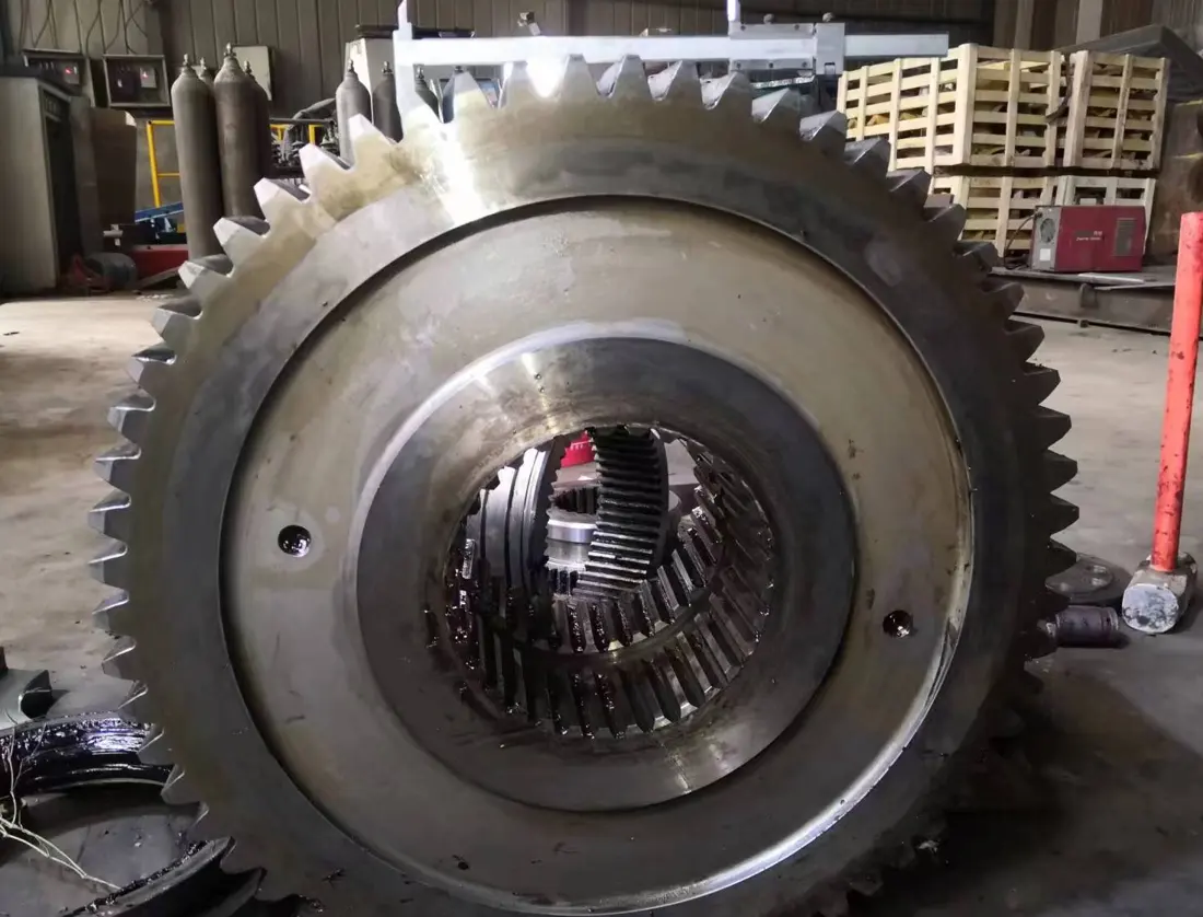
ترس حلقي / ترس حلقي
لأنظمة الإدارة أحادية أو مزدوجة الترس. طابق المفاصل المنقسمة، وهندسة الأسنان، والجريان، وعلامات التزاوج ومسندات التثبيت كنظام.
عرض تفاصيل الجزء →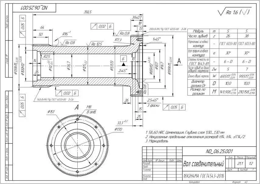
محور دوران المطحنة
تحمل هذه الأجزاء الأحمال وتوفر وصلات التغذية والتفريغ في المطاحن المدعومة على مرتكزات الدوران. طابق الفلنجات ومناطق ارتكاز العمود والتجاويف وأنصاف أقطار الوصل وتمركز المحاور وتوافقات المحامل مع رسم الترتيب العام.
عرض تفاصيل الجزء →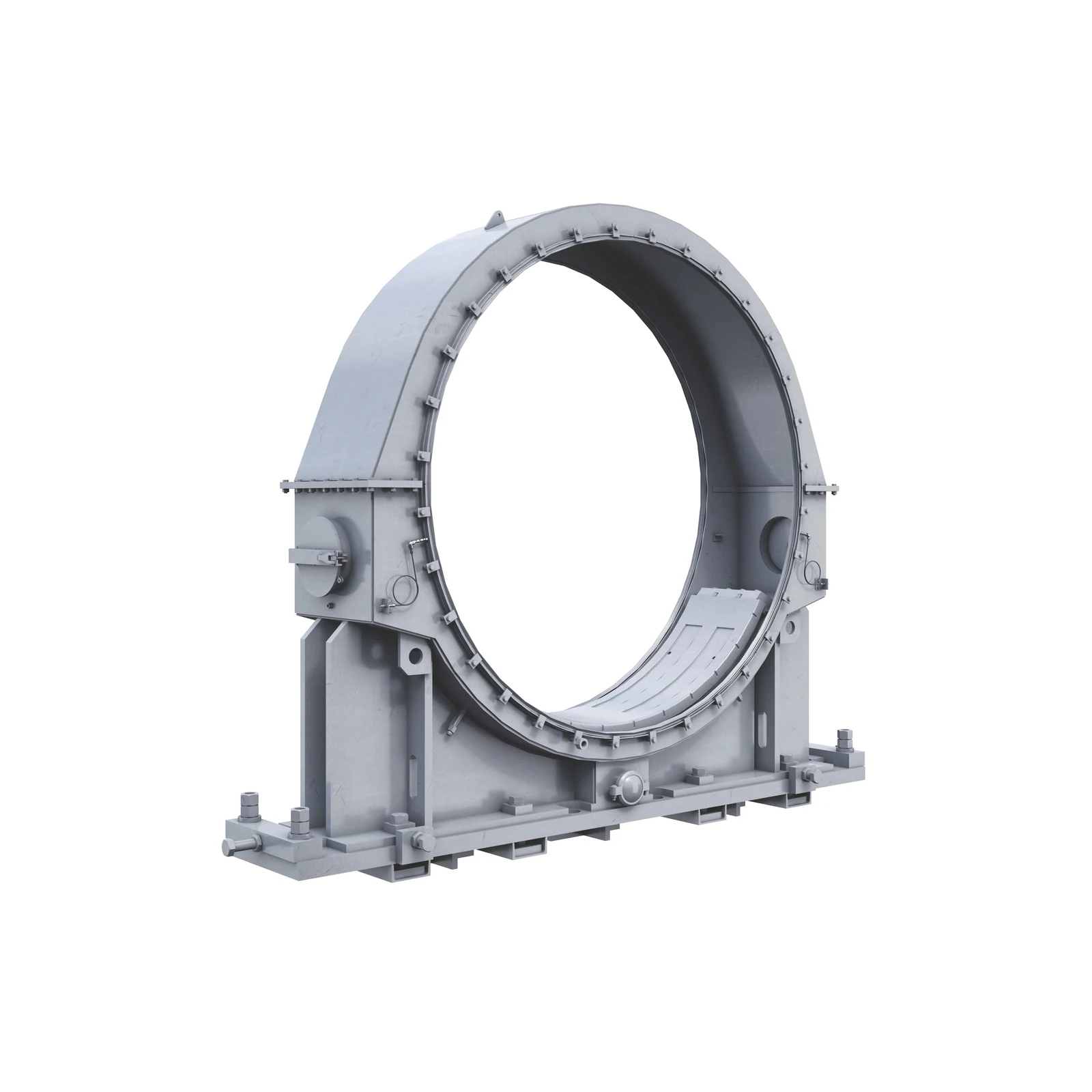
محمل محور الدوران & جلبة محمل
لتكوينات المحامل الانزلاقية. طابق قطر منطقة ارتكاز العمود ونصف قطر سطح المحمل وأخاديد الزيت وفتحات قياس الحرارة وطبقات بابيت أو بنية سبيكة النحاس.
عرض تفاصيل الجزء →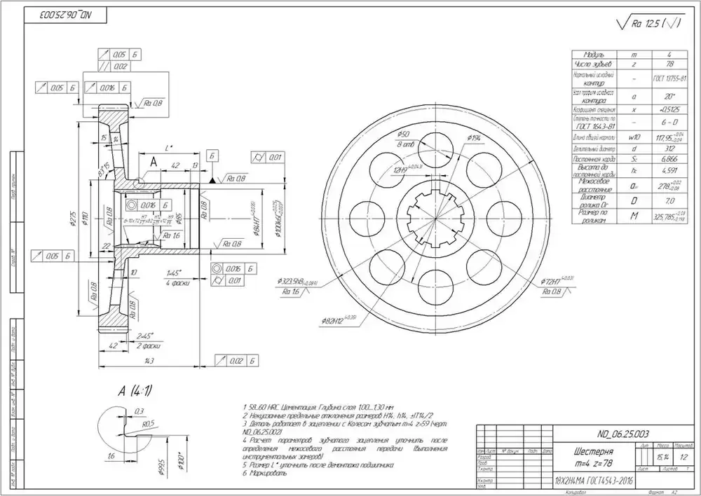
أجزاء إدارة للخدمة الشاقة
وتشمل هذه أعمدة القيادة، والوصلات، وواجهات المخفض، وأكمام العمود والمثبتات. حددها بشكل منفصل بالنسبة لأنظمة الإدارة عالية السرعة أو المباشرة منخفضة السرعة أو بدون تروس.
عرض تفاصيل الجزء →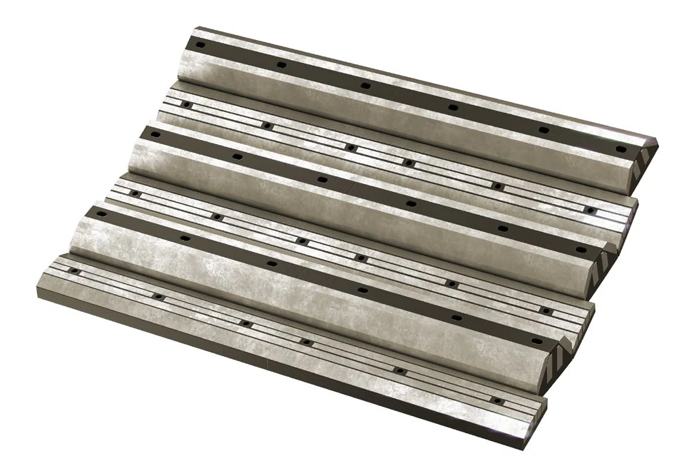
مثبت البطانة & طقم موانع تسرب
تشمل براغي البطانات والصواميل والوردات والحشيات وأجزاء التثبيت المرتبطة بها. طابق فئة البرغي وطوله ونوع الرأس ومواضع الثقوب مع البطانات.
إرسال الرسومات والأرقام →استخدم لوحة اسم الجهاز والرقم التسلسلي وقطر المطحنة والطول الفعال وترتيب الدعم وتكوين الإدارة والترتيب العام معا. المظهر وحده لا يكفي
ابدأ بتقديم الرسم وطراز المعدات المطابق وموضع التركيب وصور الجزء المستخدم والأبعاد الأساسية. تساعد هذه المعلومات في المطابقة مع رسم الجزء وBOM ورسومات التركيب.
ليس بالضرورة. تعمل أنظمة تفريغ نهاية التغذية، والأسطوانة، ونهاية التفريغ، وتفريغ الملاط في ظل ظروف مختلفة. طابق المواد والهيكل بشكل منفصل حسب الموقع ووضع الفشل والتصميم الأصلي.
قم بتوفير القطر × الطول الفعال، وترتيبات الدعم والقيادة، والرقم التسلسلي، وموضع التثبيت، وOEM/الرسم، وصور الأجزاء المستخدمة، والرسومات، وظروف التشغيل. نحن نستخدم هذه لتحديد الأجزاء وتقييم المواد ومطابقة متطلبات التصنيع ومراقبة الجودة وتسليم المكونات النهائية.
أو تواصل معنا مباشرة: +86 156 3797 3199
zzx@anranst.com
تقدّم ANRANST لعملائها حول العالم التقييم الهندسي والإنتاج في مسابك معتمدة وفق المتطلبات الفنية للعميل ومراقبة الجودة وتسليم القطع الجاهزة لقطع التآكل المخصّصة وقطع الغيار الصناعية، مع إمكانية دعم قطع صناعية مخصّصة أخرى.
نراجع أسطح التزاوج وأبعاد الوصلات، ونقيّم إمكانية التصنيع من حيث المادة والمعالجة الحرارية.
Material grades and heat-treatment processes are specified order by order, stated in the technical agreement and tracked through production.
تأكيد الرسم، ومراقبة المواد والعمليات، ومتابعة الإنتاج، والفحص، وتنسيق القبول.
ننسّق التصنيع وتأكيد الجودة والتغليف والتسليم للقطع الكاملة ضمن سلسلة توريد متكاملة وعملية.
زوّدنا بالطراز الحالي والرسومات والمواد أو ظروف التشغيل لنتمكن من تحديد المراجعة الفنية ومسار التوريد المناسبين.
أرسل استفساراً