FLS الكسارات الدورانية TSUV وTS وNT وKB Pro

Start with standard models and key dimensions to identify spider and liner wear systems, main shafts and drive spares, then confirm materials, dedicated tools and drawing numbers for an enquiry.

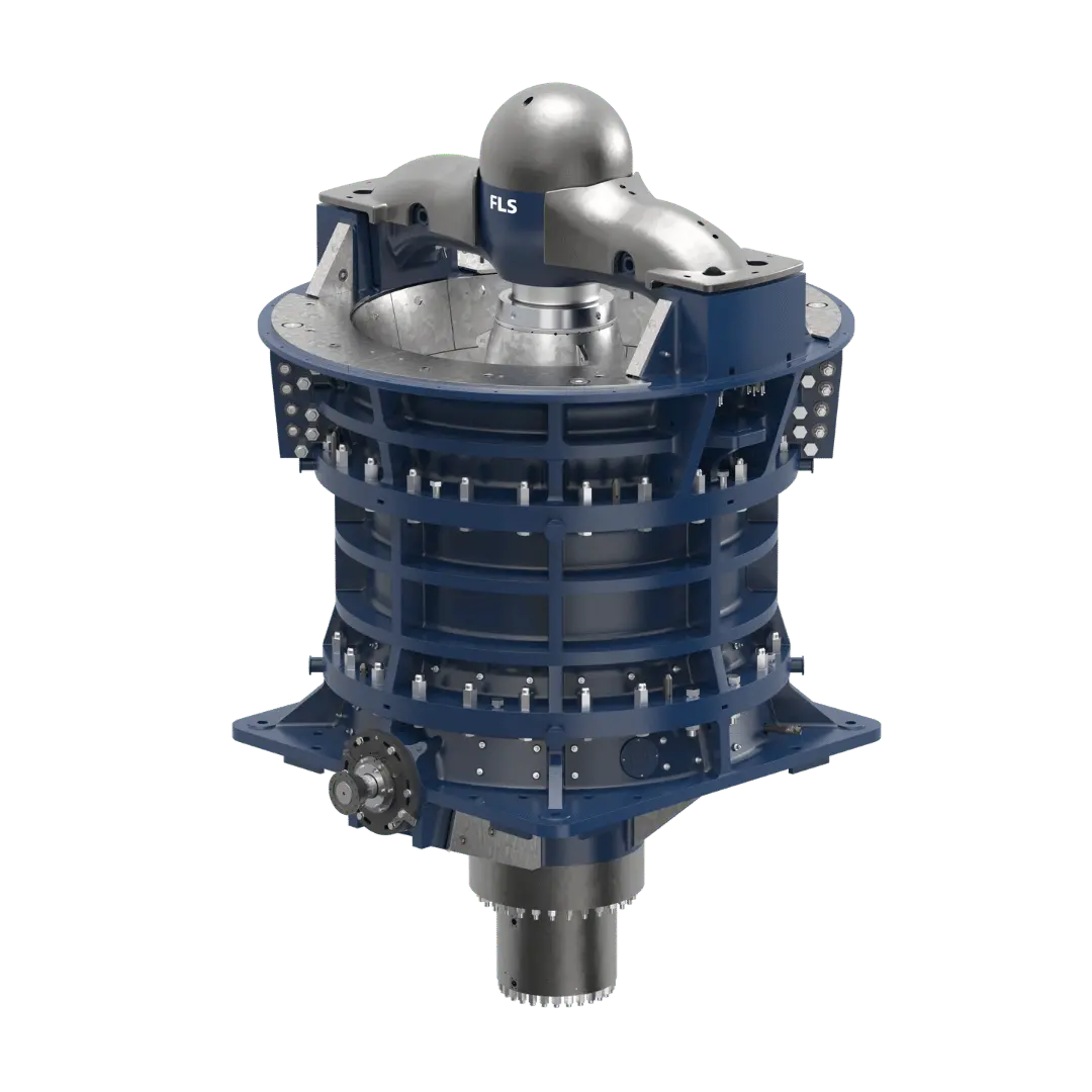
Official FLS TSUV gyratory crusher machine image
Official FLS TSUV machine image. Identify the TSUV, TS/TSU, NT or KB Pro family and full specification before checking individual equipment.
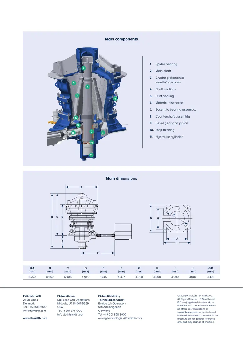
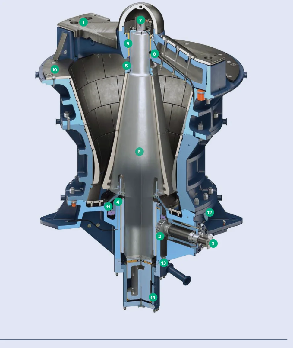
Official FLS KB 63-80 Pro component and dimension drawing
Official FLS KB 63-80 Pro component and dimension page, identifying spider bearings, main shaft, liners, eccentric, drive, thrust support and hydraulic cylinder positions.
OEM المعدات التفاصيل

Models, wear parts, spares and tools on one page

The current FLS range retains TSUV, TS, NT and الكسارة الدورانية Pro. This page covers specifications, installation positions, materials and tools directly relevant to spare identification.

8 Official specification entries
54–63 in KB Pro feed opening
4,300–14,500 tph Published KB Pro capacity
3 Dedicated tools with official documentation
Standard Models and Key Dimensions

TSUV, TSU, NT and KB Pro specifications

TSU and NT data come from the current FLS website comparison table. KB Pro feed openings, mantle diameters, capacities and powers come from individual official datasheets. Confirm final requirements against the nameplate, serial number and project configuration.

Series / modelالمعدات typeFeed openingبطانة المخروط المتحرك diameterCapacity (tph)Installed power (kW)
TSUVCurrent Top Service Ultra-Velocity seriesConfirm for the specific specificationConfirm for the specific specificationUp to 15,000Up to 1,500
TSU 63 × 118Top Service specification in the official website comparison63 in118 in10,0001,200
NT 60 × 113Fuller NT specification in the official website comparison60 in113 in6,0001,000
KB 54-67 Proالكسارة الدورانية Pro1,370 mm1,700 mm4,300500
KB 54-75 Proالكسارة الدورانية Pro1,370 mm1,900 mm5,300650
KB 63-80 Proالكسارة الدورانية Pro1,600 mm2,030 mm6,000750
KB 63-89 Proالكسارة الدورانية Pro1,600 mm2,260 mm8,5001,000
KB 63-130 Proالكسارة الدورانية Pro1,600 mm3,300 mm14,5001,500

KB Pro datasheet capacities are calculated for specified material conditions. Actual capacity, power, eccentricity and discharge setting vary with ore characteristics and chamber configuration.

قطع الغيار المستهلكة

Spider, concave, mantle and shell wear protection

Start with spider protection, concaves, mantles and main shaft protective sleeves, then review support, shell, hub and feed protection positions. Each card links to the relevant part and material pages.

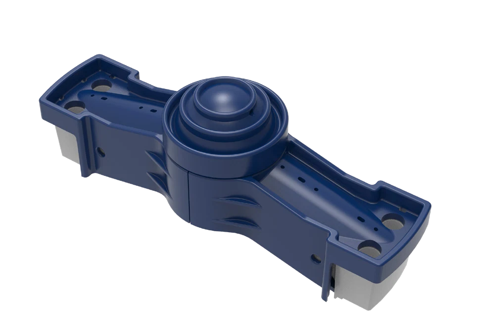
Spider shields, caps and arm guards identification image
01

Spider Shields, Caps and Arm Guards

Spider Cap, Shield & Arm Liner

Located above the feed opening, these withstand large-rock impact, sliding wear and uneven drop loading. Check spider structure, arm count, plate profile, hole pattern, thickness and feed direction.

Material Selection:Confirm high-manganese steel, quenched and tempered wear plate or composite wear protection according to impact energy, thickness and fastening method.

View Part التفاصيل →
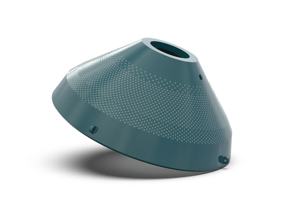
Concave identification image
02

Concave Liners

Concaves

Concaves fit in segments around the upper shell and form the chamber with the mantle. Check chamber profile, tier count, segmentation, support rings, backing clearance and wear profile at each tier.

Material Selection:Use high-manganese steel, specialty alloys or composite wear systems validated for the ore conditions. Confirm chemistry and heat treatment against drawings.

View Part التفاصيل →
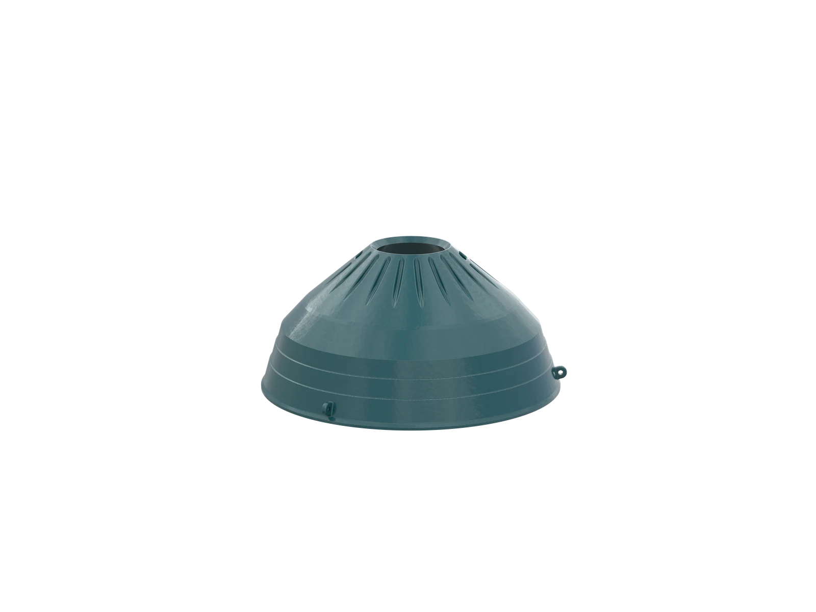
بطانة المخروط المتحرك identification image
03

بطانة المخروط المتحرك

بطانة المخروط المتحرك

The mantle covers the main shaft cone and moves with its gyratory motion, working against the concaves. Check upper/lower profiles, head nut interface, backing, closed-side setting and wear zones.

Material Selection:Confirm high-manganese steel or specialty wear alloys according to the combined impact, compression and abrasion conditions.

View Part التفاصيل →
Main shaft protective sleeve identification image
04

العمود الرئيسي Protective Sleeve

Mainshaft Sleeve

This separate protective component fits around the main shaft; it is not the main shaft assembly. Check shaft diameter, mating length, wall thickness, end location and assembly/removal structure.

Material Selection:Confirm forged or quenched and tempered alloy steel and surface strengthening against original drawings, fits and wear position.

View Part التفاصيل →
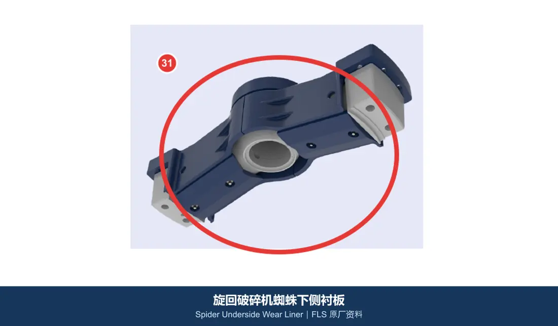
Spider underside liner identification image
05

Spider Underside Liners

Spider Underside Wear Liner

These protect the underside of spider or support structures from ore rebound and sliding wear. Check left/right positions, plate profile, hole pattern, assembly clearances and adjacent guards.

Material Selection:Confirm high-manganese steel, quenched and tempered wear plate or bimetallic composite plate according to the balance of impact and sliding wear.

View Part التفاصيل →
Upper shell wear plate identification image
06

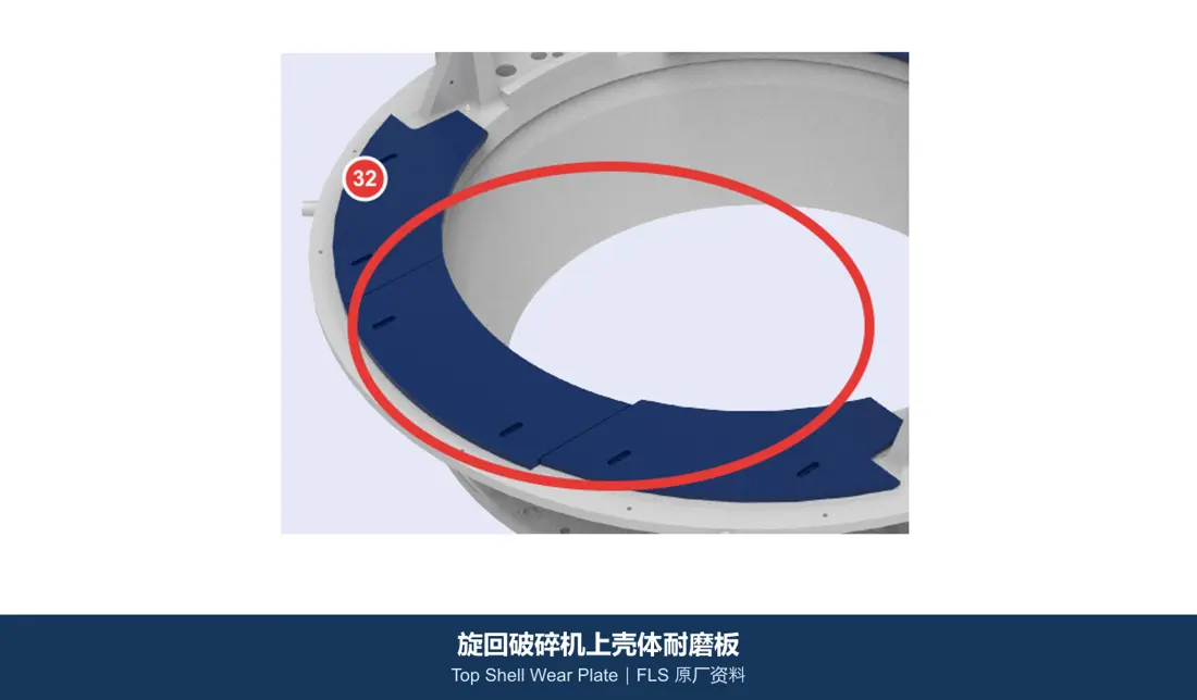
Upper Shell Wear Plates

Top Shell Wear Plate

These plates protect upper shell structural surfaces from falling material, rebound and localized abrasion. Check shell level, plate numbers, overlap direction, thickness and fastening structure.

Material Selection:Confirm quenched and tempered wear plate, bimetallic composite or high-chromium wear protection according to installation space and impact intensity.

View Part التفاصيل →
ترس صغير shaft arm guard identification image
08

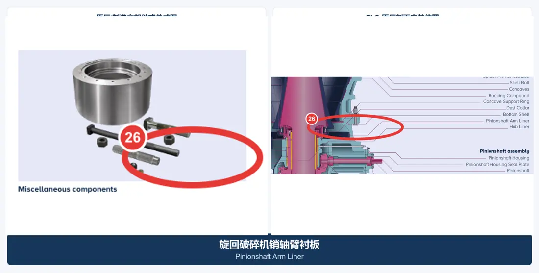
ترس صغير Shaft Arm Guards

Pinionshaft Arm Liner

These protect shell or arm structures near the pinion shaft and discharge area. Check machine side, installation direction, interference clearance, plate thickness and hole pattern.

Material Selection:Confirm high-manganese steel, quenched and tempered wear plate or bimetallic composites according to impact and abrasion.

View Part التفاصيل →
قطع الغيار

Main shafts, eccentrics, gears, bearings, hydraulics and seals

Identify main shaft assemblies separately from protective sleeves. Check drive, load-bearing and hydraulic spares against series, full model, machine side, drawing revision and mating dimensions.

Main shaft assembly identification image
01

العمود الرئيسي Assemblies

Mainshaft Assembly

Position 2 in the official FLS KB Pro component drawing. The assembly includes the main shaft and its assembly relationships and must be distinguished from the separate protective sleeve.

Material Selection:Confirm large forged alloy steel, heat treatment, journal accuracy and non-destructive testing against model, loads and original drawings.

View Part التفاصيل →
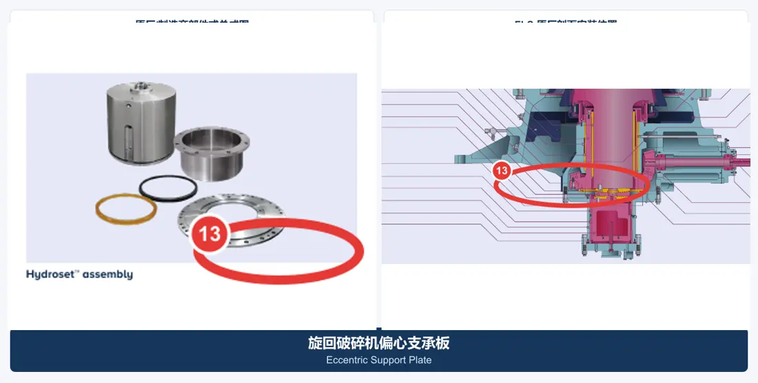
Eccentric assembly identification image
02

Eccentric Assemblies

Eccentric Bearing Assembly

Position 7 in the official FLS KB Pro component drawing. Check eccentricity, rotation direction, internal/external fits, support plates, lubrication passages and top/bottom orientation.

Material Selection:Load-bearing steel components work with bearing copper alloys. Confirm materials, clearances and oil grooves against original drawings.

View Part التفاصيل →
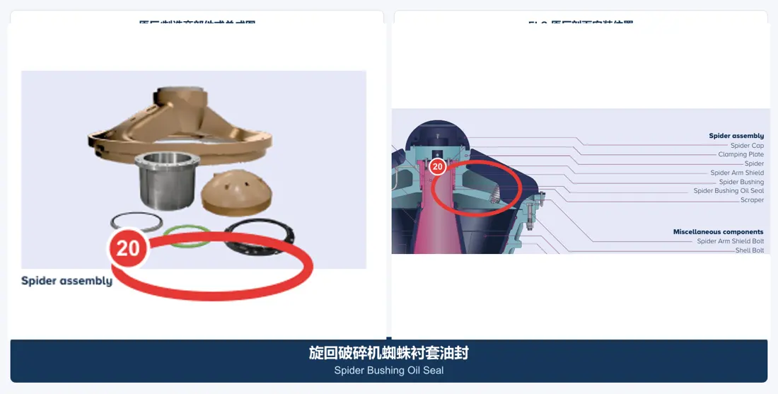
Spider bushings and oil seals identification image
03

Spider Bushings and Oil الموانع

Spider Bushing & Oil Seal

These support the upper main shaft and maintain lubrication. Check support structure, shaft diameter, bushing inside/outside diameters, flange, oil grooves, seal lips and lubricant.

Material Selection:Use bearing copper alloys with NBR, HNBR, FKM or other seal materials confirmed for the fluid and temperature.

View Part التفاصيل →
ترس صغير shaft assembly identification image
04

ترس صغير Shaft Assemblies

Countershaft / Pinionshaft Assembly

Position 8 in the official FLS KB Pro component drawing. Check shaft diameter, bearing seats, gear interfaces, rotation direction, seals, end covers and coupling structure.

Material Selection:Confirm forged transmission alloy steel, bearing steel and seal materials according to load, speed, heat treatment and accuracy grade.

View Part التفاصيل →
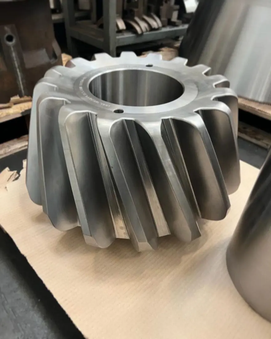
Gear wheel and pinion identification image
05

Gear Wheels and Pinions

Bevel Gear & ترس صغير

Position 9 in the official FLS KB Pro component drawing. Check module, tooth counts, pressure angle, helix direction, mounting distance, backlash and contact pattern as a matched pair.

Material Selection:Confirm carburized or quenched and tempered transmission alloy steel, tooth hardness, core toughness, grinding and matched-pair inspection against the original design.

View Part التفاصيل →
Main shaft step plates and thrust supports identification image
06

العمود الرئيسي Step Plates and Thrust Supports

Step Bearing Components

Position 10 in the official FLS KB Pro component drawing. Check stacking order, contact diameters, oil film clearance, thrust faces and hydraulic adjustment structure.

اختيار المادة: أكِّد فولاذ السبائك المقاوم للتآكل وسبائك النحاس للمحامل وفقًا لضغط المحمل والتزييت والتسطيح ومتطلبات الملاءمة.

View Part التفاصيل →
Hydraulic cylinder and adjustment assembly identification image
07

Hydraulic Cylinders and Adjustment Assemblies

Hydraulic Cylinder & Adjustment Assembly

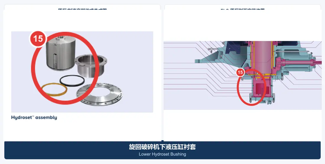
Position 11 in the official FLS KB Pro component drawing. Check bore, stroke, pressure, support bushings, seal grooves, piping interfaces and controls.

Material Selection:Confirm hydraulic cylinder alloy steel, support copper alloys and polyurethane/NBR/HNBR/FKM seals according to pressure and fluid.

View Part التفاصيل →
Dedicated tools

Official FLS gyratory crusher maintenance tools

All three categories have official FLS datasheets and equipment-specific images. This page explains their functions; actual capacities, lifting points and interfaces must match the installed model and site maintenance plan.

Official FLS main shaft transport and maintenance stand image
01

العمود الرئيسي Transport and Maintenance Stands

Mainshaft Transport Stand

This official FLS tool supports gyratory main shaft assemblies during lifting connection and transport while protecting critical journals. Confirm support points, capacity and interfaces against the shaft model.

Submit Model and Tool Requirements →
Official FLS head nut and safety tool upgrade image
02

Head Nut and Safety Tool Upgrades

Headnut & Safety Tool Upgrade

These official FLS tools tighten and remove head nuts, reducing direct personnel involvement and improving assembly work. Confirm applicable models, reaction structures and operating space against the installation.

Submit Model and Tool Requirements →
Drawing and spare part numbers

Match known OEM or third-party numbers to models and positions

When submitting a number, include the full series and model, serial number, part name, installation position, general arrangement or assembly drawing, used-part photos and critical dimensions. We use these to establish traceable matches.

How is a specific FLS gyratory crusher model confirmed?

First distinguish TSUV, TS/TSU, NT or KB Pro, then check the complete specification, serial number, feed opening, mantle diameter, general arrangement drawing and drawing revision.

هل العمود الرئيسي وجلبته الواقية مكوّن واحد؟

No. The main shaft is a core load-bearing component, while its protective sleeve is a separate part fitted around it. Check drawing numbers, dimensions and materials independently.

Can third-party drawing numbers and tooling requirements be checked together?

Yes. Submit the third-party number, full model, equipment general arrangement drawing, installation position and used-part information. These support checks of part cross-references and maintenance tool interfaces together.

Submit FLS gyratory crusher models, drawing numbers, liner layouts or tooling requirements

Provide the series and full model, serial number, OEM/third-party number, drawings, used-part photos, material and operating conditions. We use these to identify parts, assess materials, match manufacturing requirements, control quality and deliver finished components.

طلب مراجعة المشروع

رقم الهاتف: +86 156 3797 3199
zzx@anranst.com

خدمات صنع في الصين

من التقييم الفني إلى تسليم المنتج بالكامل

توفر شركة ANRANST للعملاء العالميين تقييمات هندسية، واختيار التصنيع الصيني، ومراقبة الجودة، وتسليم الأجزاء النهائية لقطع الغيار الصناعية المقاومة للتآكل حسب الطلب، ويمكنها أيضًا دعم قطع الغيار الصناعية الأخرى حسب الطلب.

01

مراجعة الرسومات والهندسة

قم بمراجعة أسطح التزاوج وأبعاد الواجهة، وقم بتقييم جدوى المواد والمعالجة الحرارية والتصنيع.

02

تحديد المادة والمعالجة الحرارية

تُحدَّد درجات المواد وعمليات المعالجة الحرارية لكل طلب على حدة، وتُثبَّت في الاتفاقية الفنية وتُتابَع أثناء الإنتاج.

03

ضبط الجودة

يشمل ذلك تأكيد الرسم، ومراقبة المواد والعمليات، وتتبع الإنتاج، وتنسيق عمليات الفحص والقبول.

04

تسليم المنتج النهائي

تنظيم عمليات التصنيع والتحقق من الجودة والتعبئة والتغليف وتسليم المنتجات النهائية الكاملة لتشكيل حلقة إمداد قابلة للتنفيذ.

قم بتزويدنا بالنماذج الحالية، والرسومات، وأرقام الرسومات، وأرقام الأجزاء، والمواد، أو معلومات ظروف التشغيل، وسنقوم بتحديد التحقق الفني ومسار التوريد وفقًا لذلك.

إرسال طلب