FLS EB and EB Pro Jaw Crushers

Start with six standard models and key dimensions to identify fixed and swing jaw plates, cheek plates, eccentric shafts, bearings, toggle plates, tensioning, adjustment and seal spares, then confirm materials and drawing for an enquiry.

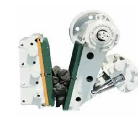
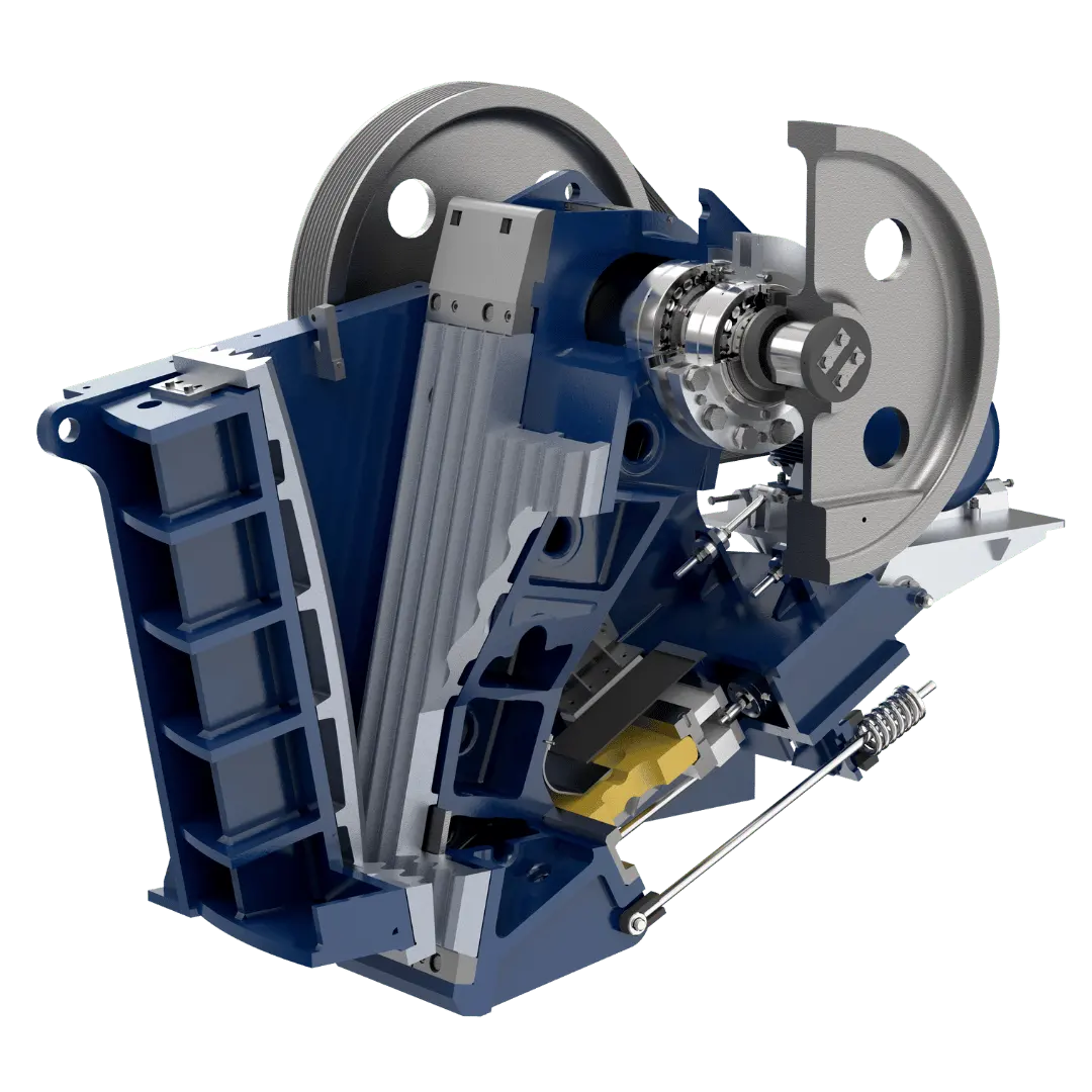
Official FLS EB jaw crusher cutaway
Official FLS EB cutaway, showing fixed and swing jaws, jaw plates, eccentric shaft, flywheel, toggle plate and tensioning mechanism.
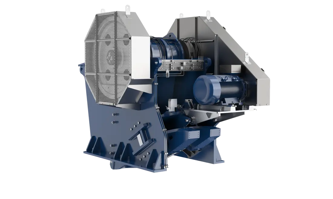
Official FLS EB jaw crusher drive and lubrication side view
Official FLS EB drive and lubrication side view, showing the flywheel, bearings, lubrication piping, motor and frame positions.
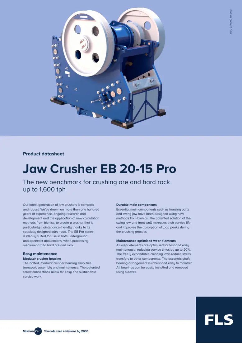
First page of the official FLS EB 20-15 Pro datasheet
First page of the official FLS EB 20-15 Pro datasheet. The model table also includes five other EB and EB Pro sizes.
OEM Equipment Details

Models, wear parts, spares and materials on one page

EB and EB Pro are single-toggle jaw crushers. This page covers the standard models, dimensions, installation positions, material selection, drawing checks and enquiry information directly needed for spare identification.

6Published standard models
7Wear parts
9Core spares
7Official sources
Standard Models and Key Dimensions

EB 09-07 to EB 20-15 Pro

Capacity, feed opening, CSS, speed, drive power, equipment weight and overall dimensions come from the corresponding official FLS datasheets.

ModelCapacityFeed opening A×BCSS rangeRecommended speedMotor powerEquipment weightOverall dimensions L×W×H
EB 09-07104–288 t/h700 × 900 mm50–175 mm200–230 rpm90 kW (up to 110 kW)Approximately 16,000 kgApproximately 3,350 × 2,150 × 2,840 mm
EB 11-08164–446 t/h800 × 1,100 mm70–225 mm200–230 rpm110 kW (up to 132 kW)Approximately 28,000 kgApproximately 4,350 × 2,700 × 2,900 mm
EB 12-10207–523 t/h1,000 × 1,200 mm100–250 mm180–200 rpm132 kW (up to 160 kW)Approximately 45,000 kgApproximately 4,780 × 2,750 × 3,300 mm
EB 14-11 Pro300–675 t/h1,100 × 1,400 mm100–250 mm160–180 rpm160 kW (up to 200 kW)Approximately 55,000 kgApproximately 4,100 × 3,180 × 3,430 mm
EB 16-12 Pro400–1,200 t/h1,200 × 1,600 mm100–220 mm145–160 rpm200 kW (up to 250 kW)Approximately 80,000 kgApproximately 4,500 × 3,300 × 4,000 mm
EB 20-15 Pro600–1,600 t/h1,500 × 2,000 mm130–230 mm145–160 rpm315 kW (up to 370 kW)Approximately 130,000 kgApproximately 5,260 × 4,070 × 4,720 mm
Capacity depends on bulk density, compressive strength, size distribution, moisture, target product size and actual CSS. Confirm final spares against the full model, serial number, drawing revision and installation dimensions.
FLS

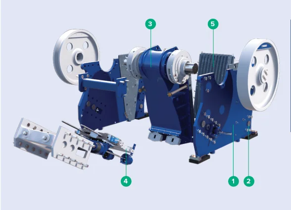
Component Location Diagram

The numbers on the diagram correspond one to one with the rows below.

FLS EB and EB Pro Jaw Crushers – Component Location Diagram
No.ComponentLocationApplies to
1Modular housingSupporting crusher housingEB14-11Pro
2Patented screw connectionJoints between housing modulesEB14-11Pro
3Swing jaw with bearingMoving side of the crushing chamberEB14-11Pro
4Gap adjustmentBehind the lower swing jawEB14-11Pro
5Segmented fixed jawFixed side of the crushing chamberEB14-11Pro
Wear Parts

Fixed jaws, swing jaws, cheek plates and body protection

Start with fixed and swing jaw plates, followed by upper/lower cheek plates, intermediate plates, feed guides and structural protection plates. Each item links to its part and material pages.

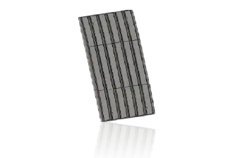
Fixed jaw plate position in the FLS EB
01

Fixed Jaw Plates

Fixed Jaw Plate

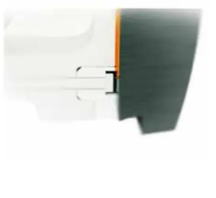
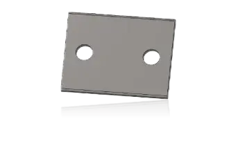
Fixed jaw plates attach inside the front wall and form the chamber with the swing jaw plates. Check model, one-piece/segmented construction, tooth profile, top/bottom direction, thickness, hole pattern, clamping method, CSS and used-part wear profile.

View Part Details →
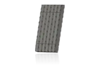
Swing jaw plate position in the FLS EB
02

Swing Jaw Plates

Movable / Swing Jaw Plate

Mounted on the swing jaw body, these are the main wear surfaces under cyclic load. Check tooth profile, relative tooth peak positions, plate width, top/bottom location, clamping wedges and pairing with the fixed jaw plates.

View Part Details →
Spare Parts

Eccentric shafts, bearings, toggle plates, tensioning, adjustment and seals

Parts with the same name are not interchangeable by appearance across EB models, sides or generations. Check drawing, fits, dimensional relationships, materials and function.

Eccentric shaft position in the FLS EB
01

Eccentric Shafts

Eccentric Shaft

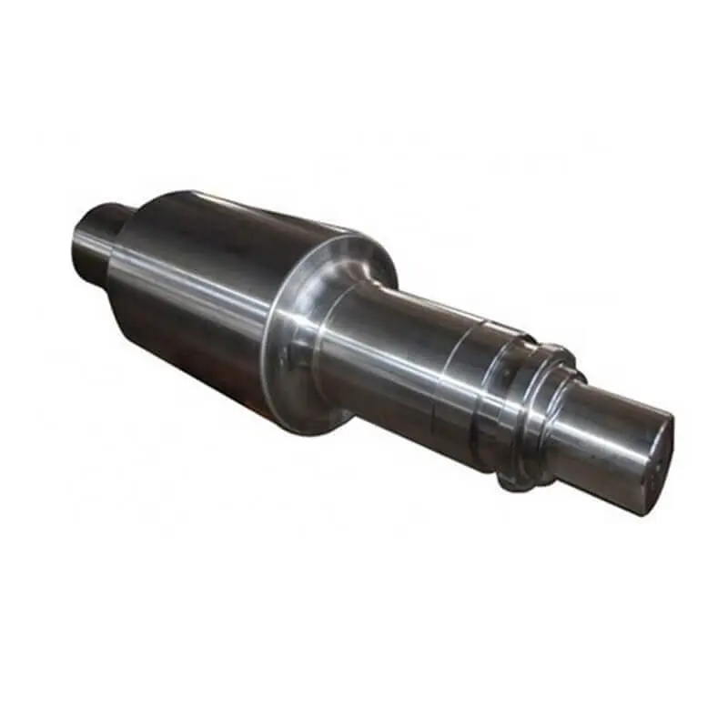
The shaft drives reciprocating swing jaw movement. Check eccentricity, journals, overall length, flywheel/pulley end, keyways, threads, bearing fits, rotation direction and dynamic balance requirements.

View Part Details →
Spherical roller bearing positions in the FLS EB
02

Spherical Roller Bearings

Spherical Roller Bearing

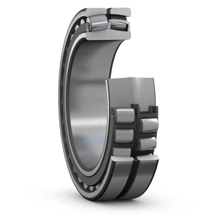
These support the eccentric shaft and swing jaw under radial impact and assembly misalignment. Check bearing model, clearance, shaft/housing fits, locating end, adapter sleeve, seals, lubrication and temperature rise.

View Part Details →
Toggle seat positions in the FLS EB
04

Toggle Seats

Toggle Seat

These support toggle plate ends and provide oscillating contact surfaces. Check front/rear seat, length, curvature, groove profile, installation direction, contact pattern and pairing with the toggle plate.

View Part Details →
Tension rod position in the FLS EB
05

Tension Rods

Tension Rod

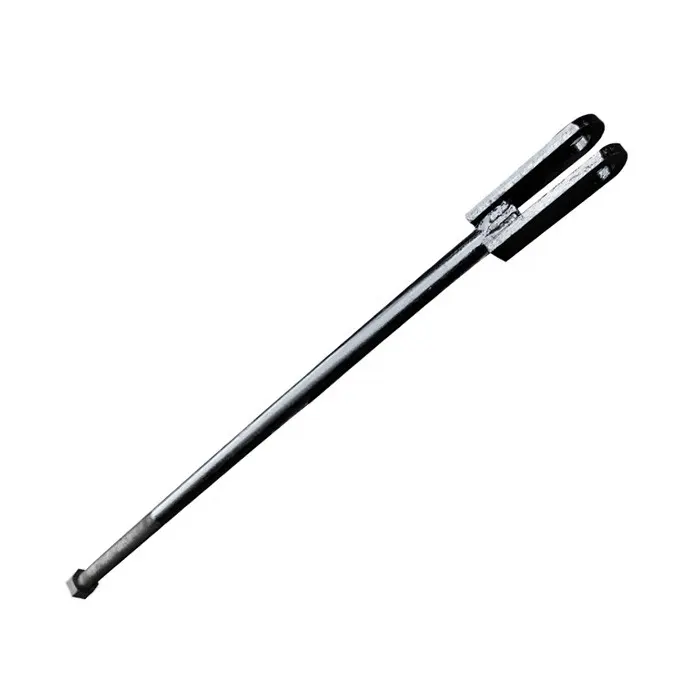
Together with the spring system, these maintain the working relationship of the toggle plate and swing jaw mechanism. Check overall length, diameter, thread, end geometry, preload position, installation direction and matching springs.

View Part Details →
Tension spring position in the FLS EB
06

Tension Springs

Tension Spring

These work with tension rods to maintain mechanism preload. Check outside diameter, wire diameter, free length, active coils, winding direction, end type and working compression.

View Part Details →
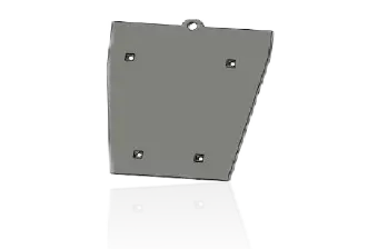
CSS adjustment wedge position in the FLS EB
07

CSS Adjustment Wedges

CSS Adjustment Wedge

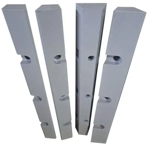
These provide mechanical or hydraulically assisted discharge setting adjustment. Check left/right and upper/lower position, taper, length, thickness, hole pattern, contact faces and actual CSS adjustment range.

View Part Details →
Jaw plate clamping wedge position in the FLS EB
08

Jaw Plate Clamping Wedges

Jaw Die Clamping Wedge

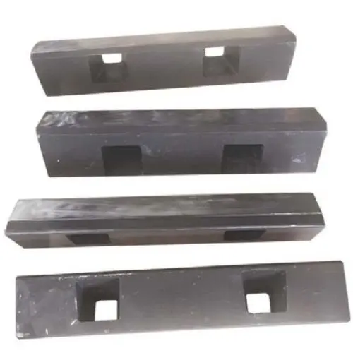
These secure fixed or swing jaw plates. Check upper/lower wedge, installation side, taper, hole pattern, threads, clamping face and jaw plate edge profile.

View Part Details →
FAQ

Frequently asked questions

Which standard FLS EB and EB Pro models are publicly listed?

Current official documents list EB 09-07, 11-08, 12-10, 14-11 Pro, 16-12 Pro and 20-15 Pro.

Is the equipment model alone enough to manufacture jaw plates?

No. Also check the serial number, drawing, fixed/swing position, one-piece/segmented construction, tooth profile, installation direction, clamping method, CSS, material and used-part wear records.

Submit FLS EB models, drawing, jaw plates or core spare requirements

Provide the full model, serial number, fixed/swing position, drawings or samples, used-part photos, critical dimensions, material and operating conditions. We use these to identify parts, assess materials, match manufacturing requirements, control quality and deliver finished components.

Equipment Brand and ModelDrawingDrawing or DimensionsCurrent MaterialPhotographs of Failed PartsTarget Service LifeOperating Conditions
Request a Quote

Or contact us directly: +86 156 3797 3199
zzx@anranst.com

Manufacturing Services in China

From Technical Assessment to Finished-Part Delivery

ANRANST provides customers worldwide with engineering assessment, production at certified foundries to the customer technical requirements, quality control and finished-part delivery for custom wear parts and industrial spares, with scope to support other custom industrial parts.

01

Drawing and Engineering Review

We review mating surfaces and interface dimensions and assess material, heat treatment and manufacturing feasibility.

02

Material and Heat-Treatment Specification

Material grades and heat-treatment processes are specified order by order, stated in the technical agreement and tracked through production.

03

Quality Control

Drawing confirmation, material and process control, production tracking, inspection and acceptance coordination.

04

Finished-Part Delivery

We coordinate manufacturing, quality confirmation, packaging and delivery of complete finished parts in a workable, closed-loop supply process.

Provide the existing model, drawings, drawing, materials or operating conditions so we can identify the appropriate technical review and supply route.

Submit an Enquiry