FLS ERC Eccentric Roll Crushers

Start with five standard models and key dimensions to identify jaw liners, roll surfaces, grates, hood wear protection, eccentric roll shafts, bearings and hydraulic spares, then confirm materials and drawing for an enquiry.

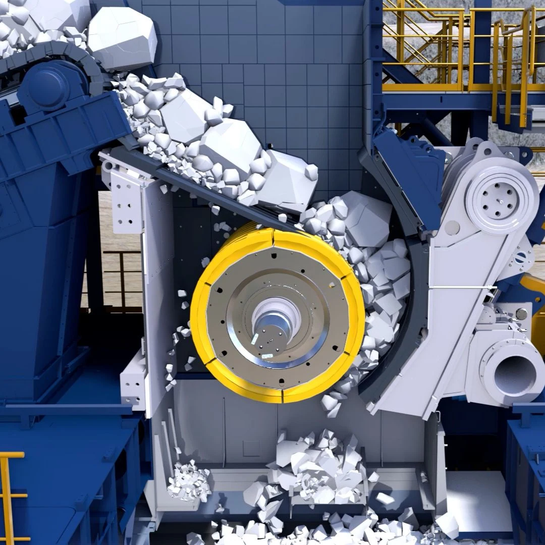
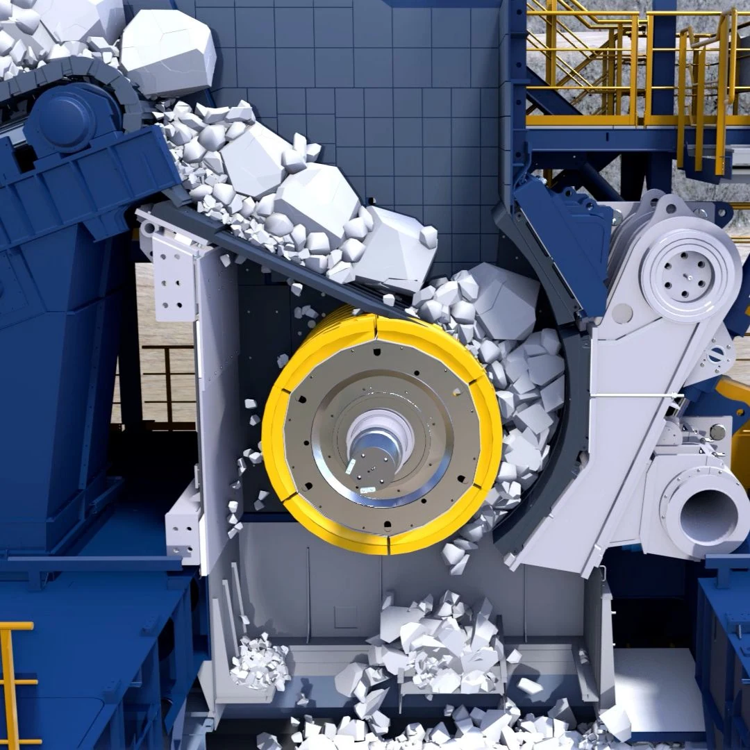
Official FLS ERC eccentric roll crusher working-area image
Official FLS ERC working-area image, showing the integrated static grate, eccentric roll, crushing jaw and lower discharge path.
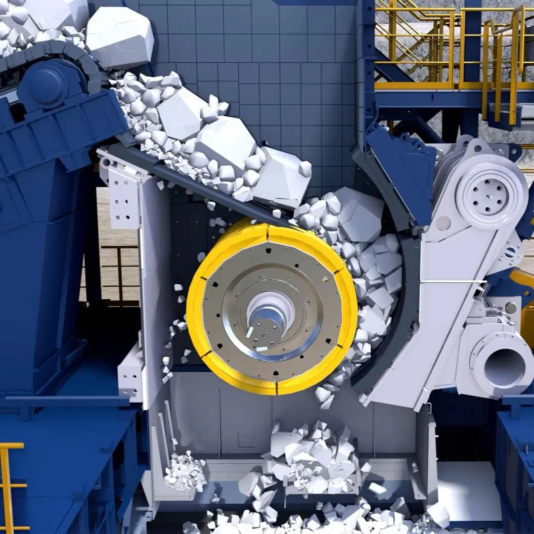
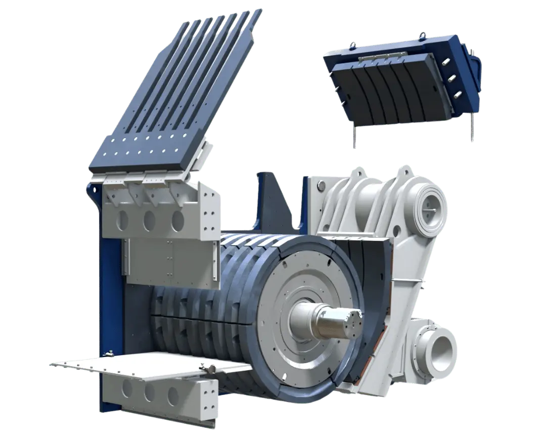
Official FLS ERC eccentric roll crusher maintenance image
Official FLS ERC maintenance image, showing the relative positions of the grate, hood, eccentric roll, crushing jaw and hydraulic adjustment structure.
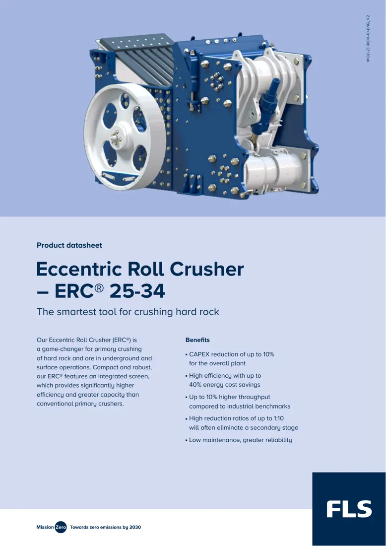
First page of the official FLS ERC 25-34 datasheet
First page of the official FLS ERC 25-34 datasheet. The model table also includes 18-14, 22-20, 25-25 and 25-30.
OEM Equipment Details

Models, wear parts, spares and materials on one page

ERC combines an eccentric single-roll crusher with a static grate. This page covers the standard models, dimensions, installation positions, material selection, drawing checks and enquiry information directly needed for spare identification.

5Published standard models
7Wear parts
3Core spares
6Official sources
Standard Models and Key Dimensions

ERC 18-14 to ERC 25-34

Models, capacity, feed opening, roll diameter and width, CSS, drive power, equipment weight and overall dimensions come from the corresponding official FLS datasheets.

ModelCapacityFeed openingRoll diameter / widthCSS rangeDrive powerEquipment weightOverall dimensions L×W×H
ERC 18-14550–1,850 t/h1,400 × 1,000 mm1,800 / 1,400 mm70–220 mm160–300 kWApproximately 83,000 kgApproximately 5,200 × 3,250 × 3,200 mm
ERC 22-201,050–3,450 t/h2,000 × 1,200 mm2,200 / 2,000 mm80–260 mm300–450 kWApproximately 156,000 kgApproximately 6,200 × 4,250 × 3,800 mm
ERC 25-251,450–4,900 t/h2,500 × 1,300 mm2,500 / 2,500 mm100–260 mm450–600 kWApproximately 185,000 kgApproximately 7,100 × 4,700 × 4,300 mm
ERC 25-302,150–7,300 t/h3,000 × 1,300 mm2,500 / 3,000 mm100–300 mm500–700 kWApproximately 215,000 kgApproximately 7,100 × 5,200 × 4,300 mm
ERC 25-342,600–8,800 t/h3,400 × 1,300 mm2,500 / 3,400 mm100–300 mm600–800 kWApproximately 240,000 kgApproximately 7,100 × 5,600 × 4,300 mm
Capacity depends on bulk density, compressive strength, size distribution, moisture, target product size and actual CSS. Confirm final spares against the full model, serial number, drawing revision and installation dimensions.
FLS

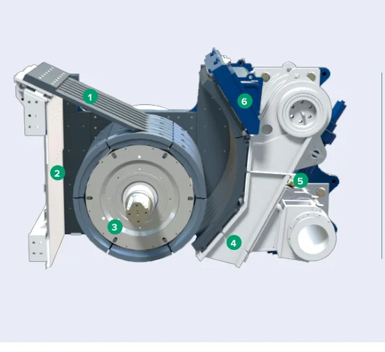
Component Location Diagram

The numbers on the diagram correspond one to one with the rows below.

FLS ERC Eccentric Roll Crushers – Component Location Diagram
No.ComponentLocationApplies to
1Integrated static grizzlyUpper feed-side screening sectionERC22-20
2HousingMachine housingERC22-20
3RollEccentric roll inside the chamberERC22-20
4JawCrushing surface opposite the rollERC22-20
5Hydraulic gap setting systemAdjustment assembly beside the crushing chamberERC22-20
6HoodTop of the housingERC22-20
Wear Parts

Crushing jaw, eccentric roll, grate, hood and discharge protection

Parts are ordered by actual installation position: jaw liners and roll surfaces in the chamber first, followed by static grates, side guards, hoods and discharge areas. Each item links to its part and material pages.

Crushing jaw liner position reference in the FLS ERC
01

Crushing Jaw Liners

Crushing Jaw Liner

Attached to the swing jaw, these form the fixed wear face on the jaw side of the ERC chamber. Check model, liner segments, tooth profile, thickness, hole pattern, assembly direction, CSS range and used-part wear profile.

View Part Details →
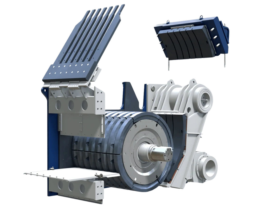
Eccentric roll liner and surface positions in the FLS ERC
02

Eccentric Roll Liners / Roll Surfaces

Roll Liner / Roll Surface

These fit around the eccentric roll and form the principal wear surface working against the jaw liners. Check roll diameter and width, segment count, circumferential location, fastenings, surface profile and rotation direction.

View Part Details →
Integrated static grate wear part positions in the FLS ERC
04

Integrated Static Grate Wear Parts

Integrated Static Grizzly Wear Parts

The integrated static grate on the feed side allows fines to bypass the crushing chamber. Check grate length, openings, bar cross-section, spacing, support positions, wear direction and replacement access.

View Part Details →
Spare Parts

Eccentric roll shafts, bearing supports and hydraulic adjustment

These three core spare categories link to their general part pages. Parts with the same name are not interchangeable by appearance across ERC models. Check structure, dimensions, loads, fits, materials and drawing.

Eccentric shaft and roll assembly positions in the FLS ERC
01

Eccentric Roll Shaft and Roll Body Assemblies

Eccentric Roll Shaft and Roll Assembly

FLS datasheets identify the roll assembly with bearings and liners as the largest transport unit. Check eccentricity, journals, roll diameter and width, bearing housing spacing, keys/locking assemblies, rotation direction and dynamic balance.

View Part Details →
FAQ

Frequently asked questions

Which standard FLS ERC models are publicly listed?

Current official documents list ERC 18-14, 22-20, 25-25, 25-30 and 25-34.

Is the equipment model alone enough to manufacture liners?

No. Also check the serial number, drawing revision, installation position, roll diameter and width, segmentation, fastening structure, material and used-part wear records.

Submit FLS ERC models, drawing, liners or core spare requirements

Provide the full model, serial number, drawings or samples, used-part photos, critical dimensions, material and operating conditions. We use these to identify parts, assess materials, match manufacturing requirements, control quality and deliver finished components.

Equipment Brand and ModelDrawingDrawing or DimensionsCurrent MaterialPhotographs of Failed PartsTarget Service LifeOperating Conditions
Request a Quote

Or contact us directly: +86 156 3797 3199
zzx@anranst.com

Manufacturing Services in China

From Technical Assessment to Finished-Part Delivery

ANRANST provides customers worldwide with engineering assessment, production at certified foundries to the customer technical requirements, quality control and finished-part delivery for custom wear parts and industrial spares, with scope to support other custom industrial parts.

01

Drawing and Engineering Review

We review mating surfaces and interface dimensions and assess material, heat treatment and manufacturing feasibility.

02

Material and Heat-Treatment Specification

Material grades and heat-treatment processes are specified order by order, stated in the technical agreement and tracked through production.

03

Quality Control

Drawing confirmation, material and process control, production tracking, inspection and acceptance coordination.

04

Finished-Part Delivery

We coordinate manufacturing, quality confirmation, packaging and delivery of complete finished parts in a workable, closed-loop supply process.

Provide the existing model, drawings, drawing, materials or operating conditions so we can identify the appropriate technical review and supply route.

Submit an Enquiry