FLS RollSizer: CenterSizer and SideSizer Models and Core Spare Parts

From RollSizer 500 – 1500 The standard number and roller length enters the crushed teeth, tooth rings laterally cranking. Liners, Roll Shafts, bearing, gear Drives and materials Confirmation.

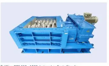
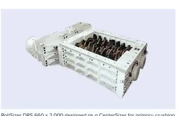
FLS RollSizer DRS 660 x 2000 CenterSizer Original Factory Product Picture
FLS In the official manual DRS 660 × 2,000 CenterSizer Primary fracture Configuration.
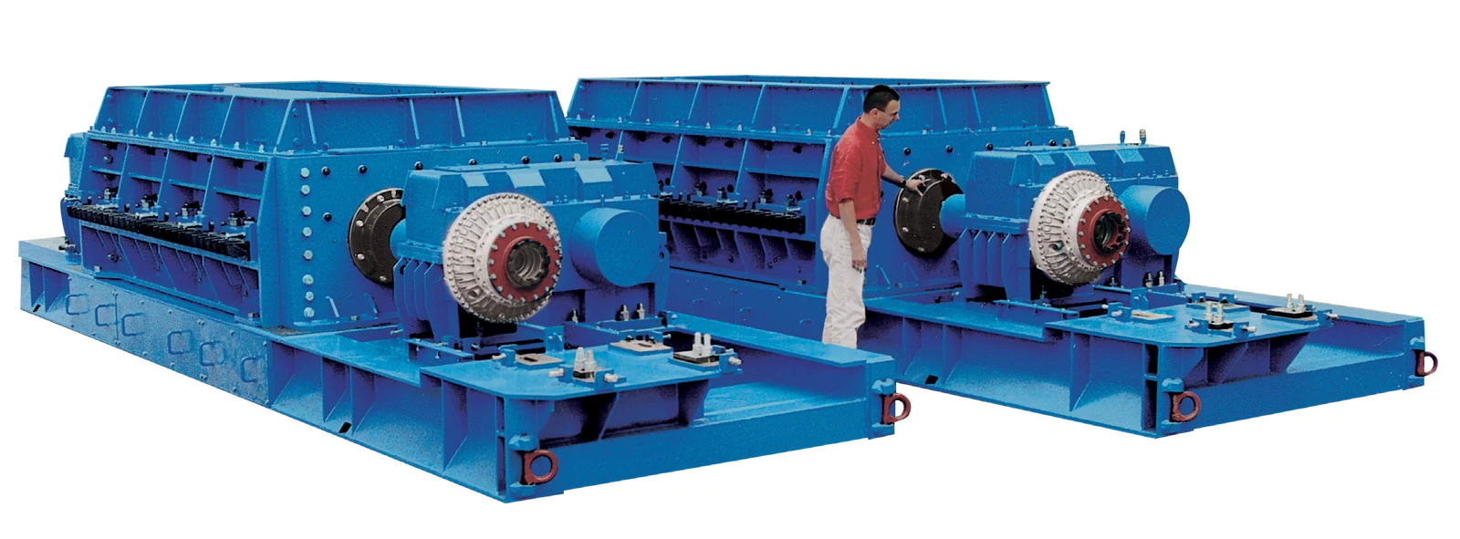
FLS RollSizer DRS 660 x 3000 SideSizer Original Factory Product Picture
FLS In the official manual DRS × SideSizer.The two rollers are tilted to the side of a broken brushing and dispersion material (660; 3,000)
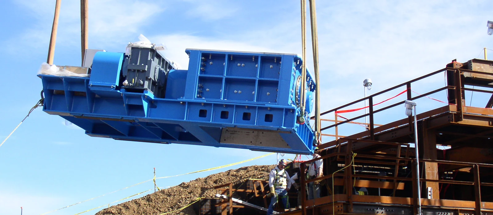
FLS RollSizer Original Factory Mounting Photos
FLS In the official manual RollSizer Photos to be checked Housing Drive, chassis and Mounting Interfaces.
OEM Equipment Details

Number of machine, rollers long and broken Geometry, wear parts and Power Transmission Completed in one page

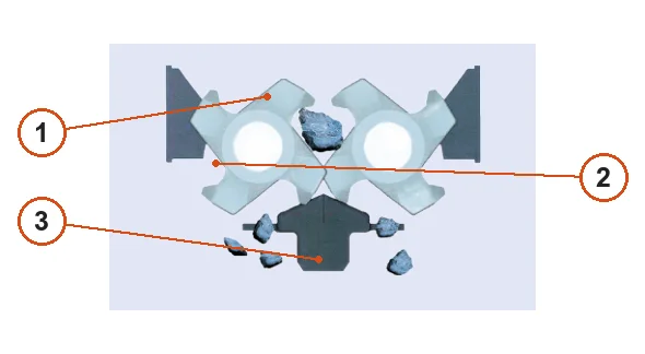
The centerSizer is broken in the middle of a double roll, and Sidesiser break between tooth roller with side comb.The same machine number can also be configured for different lengthing or driving forms as spare parts must confirm by full DRS model; serial numbers are required on canvases made from teeth rolling lines (and drawings).

6 Standard Number
2 Broken Geometry
5 wear parts Entrance
5 Drive spares Entrance
Models and Key Dimensions

RollSizer 500, 660, 800, 1,000, 1,250 and 1,500

The value is derived from the FLS official Rollsizers manual.The feed, capacity and power as well weight are examples/guide values for hard limestone with real items varying in tooth shape; material size: density of a roller length (- years)

Number of mastsStandard Roller LengthDiameter of toothtipMaximum feed Center / SideExample CapabilityInstalled PowerNon-drive weight
RollSizer 5001,000 / 1,500 / 2,000 mms YoY mm (590)– mm (SideSizer s YoY mm) (480; 650; 200)Supreme Court 1,500 t/h55–220 kWs YoY / / t (4; 5; 7)
RollSizer 6601,500 / 2,000 / 3,000 mms YoY mm (750)– mm (SideSizer s YoY mm) (650; 850; 300)Supreme Court 2,500 t/h160–500 kWs YoY / / t (17; 20; 25)
RollSizer 8001,500 / 2,000 / 3,000 mms YoY mm (920)750–1,050 mmSupreme Court 3,500 t/h200–630 kWs YoY / / t (27; 32; 40)
RollSizer 1,0002,000 / 3,000 mms YoY mm (1,020)950–1,300 mmSupreme Court 5,000 t/h250–700 kWs YoY / t (42; 51)
RollSizer 1,2502,000 / 3,000 mms YoY mm (1,450)1,200–1,600 mmSupreme Court 7,500 t/h450–800 kWs YoY / t (81; 100)
RollSizer 1,5003,000 / 4,000 mms YoY mm (1,800)1,400–2,000 mmSupreme Court 10,000 t/h750–1,200 kWs YoY / t (125; 150)
Wear Parts

Broken tooth, ring of teeth and lateral coagulations. Brake beam with shell thread

The path is broken and drained by the material into a crushing cavity, snatched tooth roller in central or side; each connection unit pages. Material Page.

Replaceable broken teeth / toothpicks in FLS RollSizer the s Construction and installation position
01

Replaceable broken teeth / toothpick

Replaceable Crushing Tooth / Tooth Pick

Installed on the tooth ring or axis of a broken roller, it is possible for them that they can grab and cut materials. Contrast CenterSizer/ Sidesiser with roll diameter as well indentation position socket shape; installation angle: dental adapter (fixing structure), rotational direction - target product particle size

Materials and Manufacturing: FLS specifies that crushing tool materials are selected according to specific material; candidate high-manganese steel, tuned/quenchable alloyy or local hardening must be confirmed by hardness and impact.

View Part Details →
The tooth ring/toe band and roller shell in FLS RollSizer the s Construction and installation position
02

Tooth Rings / Tackle and Roller Shell

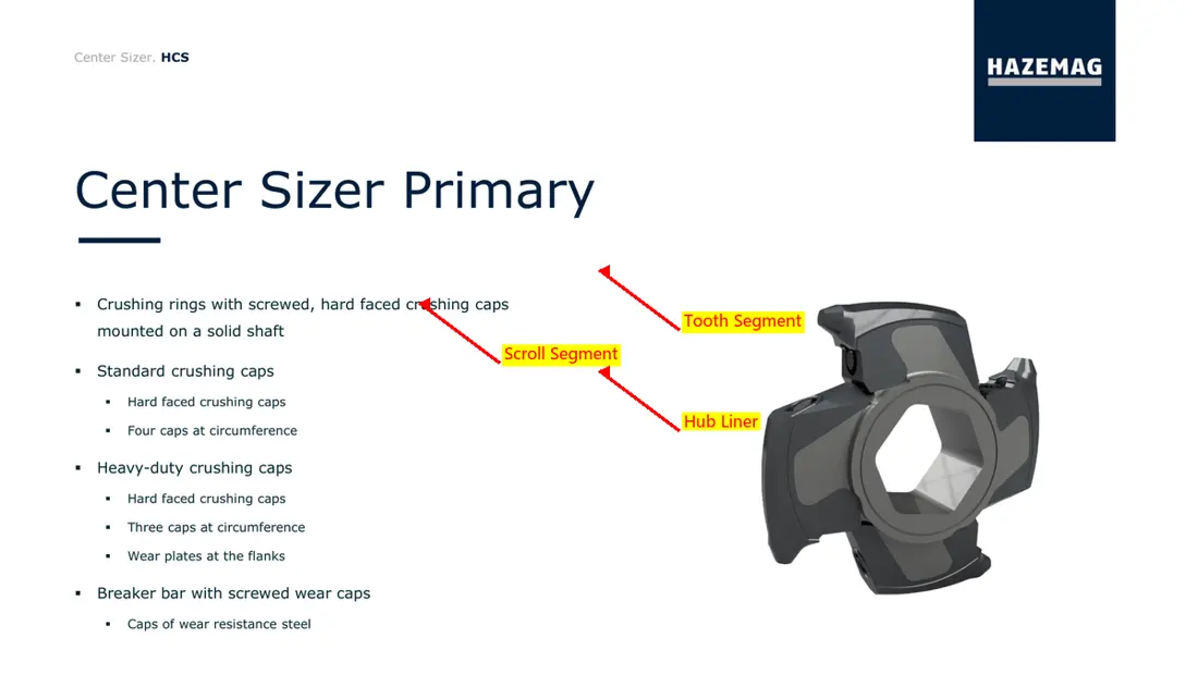
Tooth Ring / Tooth Segment and Roll Shell

The whole set of tooth rings or segments form a broken roller working profile. Contrast the diameter, length and number in sections shaped by rowing; shafts/foam key: flange (incision), sewerage - bonded with assembly order).

Materials and Manufacturing: The tooth rings and roller shells are usually filtered by a fabricable wear alloy steel system; materials, heat treatment stipulation of hardness gradientes (Glasses), welding boundary lines or NDT were determined on the drawings as well in actual impact anterioration.

View Part Details →
lateral fractured/ side liners FLS RollSizer the s Construction and installation position
03

lateral fractured/ side liners

Side Crushing Comb / Side Liner

SideSizer crushed materials between the tooth roller and adjustable broken combs on both sides; side-cooking determine product particle size. Contrast left, negator profile of a pore lineage with an adjustment range for its diameter in order that it can be used as part or other parts (or parts).

Materials and Manufacturing: Wear-Resistant Alloy Steel, Quenched and Tempered Wear Plate or Composite wear-resistant construction by Cutting, sliding abrasive erosion and blockage shocking as well AS adjustable institutional requirements.

View Part Details →
The central shattered beams / broken anvil in FLS RollSizer the s Construction and installation position
04

Central Broken Lifts / Battered Anvil

Breaker Bar / Anvil

The centralSizer's partial primary crushing configuration sets the broken beam below two roller, controlling large blocks of material to break twice. Contrast roll distance and girdle profile with teeth surface; installation height: bearing load - replaceable wear-resistant block & discharge gap

Materials and Manufacturing: High-impact areas from high resilient Wear-Resistant Cast Steel, alloy steel Or replaceable composite wear-resistant block Material Selection Not only on the average Liners materials Alternatives.

View Part Details →
The lining of the shell, terminals and Material scraping Pieces in FLS RollSizer the s Construction and installation position
05

The lining of the shell, terminals and Material scraping s

Housing Liners, End Plates and Scrapers

Protection of the fractured cavity side wall, end and bottom slab area to maintain clearance around a roller. Converging partition number with right-hand direction arcaneity plate thicknesses in diameter; pore lines: matching gap between scrapers & wear positions

Materials and Manufacturing: Quenched and Tempered Wear Plate, bimetal composite The plate or wear-resistant castings are confirmed by impact, fine rinsing and mixing.

View Part Details →
Spare Parts

Roll Shafts, bearing synchronization gear, gearboxes and couplings fasteners

High torque and low speed Power Transmission The parts are confirmed by single/double drive, shaft distances and roller length rippled with complete drawings. Equipment The shape or number of the machine is interchangeable.

Broken Roll Shafts FLS RollSizer the s Construction and installation position
01

Broken Roll Shafts

Crushing Roll Shaft

The bearing ring and the delivery of high torque. Contrast roller axis total length, shaft distances (or bearable positions), tooth rings/wavy key interface() flange-driven endpointing; rotational direction: coaxial degree - NDT & historical fixation

Materials and Manufacturing: Alloy Steels for Drive Parts Confirm by torque, bending and fatigue; matching with the junctions. materials Alternatives must be combined heat treatment and mechanical performance verification.

View Part Details →
Bearings and Bearing Housings FLS RollSizer the s Construction and installation position
02

Bearings and Bearing Housings

Bearing and Bearing Housing

The bearing is broken right and left, maintaining the axis distance between tooth surfaces. Contrast carrying codecs; gaping in a row of shaft/seat matches with each other: terminal cover sealed up by seam (lubrication), temperature monitoring positional mode or side-byside

Materials and Manufacturing: bearing Steel, Cast Steel / Ductile Iron the scaffolding, Sealing and Lubrication materials By load, Speed Effective shocks, pollution and temperature rise.

View Part Details →
synchronized level, gear With the gearbox in FLS RollSizer the s Construction and installation position
03

synchronized level, gear With gearboxes

Synchronisation Stage, Gears and Gearbox

The single-drive configuration coordinates the two rollers by synchronizing, and both drives drive each of them. Converging between driving form (transmission ratio), tooth number() moduluses; spiral direction: installation distance); axle hole/ coupling device - Lubrication & contact with teeth surface

Materials and Manufacturing: Carbon permeation or morphology Alloy Steels for Drive Parts by Tooth contact Fatigue, bending fatigues and core toughness. NDT Confirmation.

View Part Details →
Liquid force couplings and drive connections FLS RollSizer the s Construction and installation position
04

Liquid force couplings and drive connections

Fluid Coupling and Drive Connection

Connect motors, reducers and crushers to absorb start or overload shock. Converge power / speed of the wheel hole (Spin), key connector dimensions; filler fluid - masking valve-brake with electrical & hydraulic drive configuration

Materials and Manufacturing: the coupling, Shaft Sleeve, tightness and Seal Materials By torque, shocks and temperature rise.

View Part Details →
dental segment fasteners, and the adjustment of abrasions FLS RollSizer the s Construction and installation position
05

dental segment fasteners, Seating and adjusting mattresses

Tooth Fasteners, Spacers and Shims

Positioning the fractured teeth, dentures and gaps in roller lines. Converging position numbers; threaded stringings: grade level (length), headset type(r) model/pants-proofer or thickness of a compartmental layer with pumpkin combination as well for field assembly order

Materials and Manufacturing: Highly Strong fasteners and Alloy Steels for Drive Parts Confirm by pre-tension, shocks and fatigue; no direct replacement of ordinary standard parts is used.

View Part Details →
Materials and failures Template: Ways

Breaking teeth materials By impact, abrasion and adhesives tooth adapter Construction Choices

FLS official information clearly identifies materials by application, rather than a unified label. First the material hardness and corrosion resistance to wear resistant coatings are used for maximum block size of objects; first it is filtered with textured thicknesses (hardness), dry clay or wet sticking - maximal blocks in diameter as well AS shock-impact treatment from old pieces that fail again using drawings/material tests such they can be verified through heat treatments required under inspection procedures

Drawing and Spare Part Numbers

Relating the number to machine numbers, roller lengths and dentures as well.

Complete submission DRS model, serial number, CenterSizer/SideSizer, roller lengths and tooth roll layout; number of teeth. OEM/ Third-party numbers, drawings and old items materials.

CenterSizer and SideSizer parts Can we be generic?

The broken position, side combs and tooth shape are different from the discharge gap. It is necessary that complete structure be verified with a roller length of diameter or indentation; drive number shall also have been determined by serial numbers as well for drawings which must then appear on each plate (the full size)

Why do the same number still provide a roller length?

Official model Tables for the same number lists multiple standard roller length, weight and tooth segment Quantity axis and Housing Changes with the number; only Installation Identification First level.

Submission FLS RollSizer model Breaking the teeth, Roll Shafts or Drive spares Demand

Provide complete model, serial number / SideSizer roller lengths and tooth roll layout positions for teething pinpointes OEM or third party numbers; drawings of old items materials & material operating conditions. We are able through this process identify the Materials Assessment Processed Material Compatibility Data Quality Control with finished-part delivery

Manufacturing Services in China

From Technical Assessment to Finished-Part Delivery

ANRANST provides customers worldwide with coordinated consulting, supplier sourcing, quality control and finished-part delivery for custom parts, wear parts and industrial spares from China, with scope to support other custom industrial parts.

01

Technical Advice

Equipment and part identification, drawing review, material selection and manufacturing feasibility assessment.

02

Supplier Introductions

Match requirements with suitable manufacturers in China and coordinate the exchange of technical information.

03

Quality Control

Drawing confirmation, material and process control, production tracking, inspection and acceptance coordination.

04

Finished-Part Delivery

Coordinate manufacturing, quality confirmation, packaging and delivery of complete finished parts.

Provide the existing model, drawings, drawing or part numbers, materials or operating conditions so we can identify the appropriate technical review and supply route.

Submit an Enquiry