
HPGR FEED CHUTE / HOPPER LINER
HPGR Feed Chute Liner
Wear protection for impact, sliding and roll-gap throat zones · Identify by location and plate number
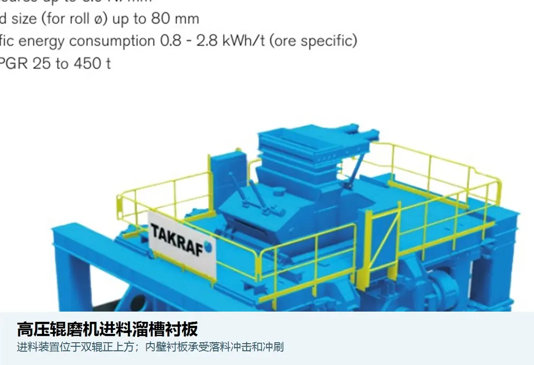
Feed chute liners protect the hopper, chute and throat above the roll gap and influence uniform feed distribution. ANRANST checks the installation zone, plate number, orientation, profile, hole pattern, material, wear history and drawing for each liner, accounting for the different duties within a chute.
System function Zone identification Feed impact zone, flow-guiding sliding zone, sidewalls and throat Plate identification Plate number, left/right orientation, upper/lower position and layout sequence Geometry identification Profile, thickness, hole pattern, recessed holes, joints and mounting datums System identification Backing plate, fasteners, clamping plates, shims and adjacent liners
Protect the feed structure and maintain stable feed to the roll gap
Loads vary by location: the feed landing zone sees impact and high-energy abrasion, inclined surfaces mainly experience sliding abrasion, and the throat above the roll gap may also experience compression, rebound and local blockages.
A liner set may combine different materials, thicknesses and fastening arrangements. Record service life by position number and select materials for each zone's duty.
Position and Performance
Divide the liner system into duty zones along the material flow
Select materials and manufacturing methods for the installation position; hardness alone is insufficient.
Feed impact zone
Subject to impact from falling large ore lumps. Prioritise toughness, support, effective thickness and fastening reliability.
Inclined sliding zone
Predominantly subject to continuous sliding abrasion. Check working-surface wear resistance, flow angle and erosion at joints.
Sidewall containment zone
Uneven feed and lateral friction can produce different wear on each side. Record both sides separately and check feed alignment.
Roll-gap throat zone
Close to the high-pressure material-bed inlet, this zone may experience compression, rebound and blockages. Verify clearances to the roll surfaces and cheek plates.
Fasteners and joints
Hole areas, recesses, bolt protection and joint orientation influence early loosening, local erosion and exposure of the supporting structure.
Modular replacement
Replacing high-wear zones separately can limit shutdown work, provided plate numbers, orientation and assembly sequence are controlled.
Materials and Manufacturing Processes
Use different material selection criteria for impact and sliding zones
Confirm grade, hardness, thickness and service-life targets against drawings, used parts and operating evidence.
Selection sequence: particle size and drop height → impact, sliding and compression by location → failure mode → material and structure → layout and fastening → drawings and acceptance → service-life records.
Failure Diagnosis
Use wear locations to distinguish material, feed and assembly problems
A record stating only “liner wear” provides too little information to guide the next material selection.
| Observed condition | Priority checks | Improvement Options |
|---|---|---|
| Cratering or fracture at the feed landing point | Drop height, maximum particle size, foreign objects, support, material toughness and effective thickness | Adjust the landing point and cushioning, and improve the impact-zone structure |
| Rapid thinning on inclined surfaces | Flow velocity, abrasiveness, angle, surface material and joint orientation | Select materials for sliding duty and optimise the liner layout |
| One-sided uneven wear | Feed misalignment, hopper buildup, flow guides, left/right plate numbers and installation condition | Restore uniform feeding before comparing material service life |
| Cracking around holes or bolt pull-through | Hole recesses, edge distances, preload, support beneath the plate, impact and material toughness | Improve hole-area design and fastening procedures |
| Loose or warped liners, or erosion at joints | Plate shape, mounting surface, heat effects, tightening sequence, joints and buildup | Restore mounting datums and control plate shape and joints |
Drawings and Inquiry Details
Identify liners using assembly positions, layout drawings and individual dimensions
Record confirmed drawing and customer model details together. Manufacture to the controlled drawing revision.
Equipment and feed system
OEM, full model, serial number, hopper/chute structure, modifications and feed arrangement.
Location and plate number
Assembly drawing position, left/right and upper/lower orientation, plate number, quantity, liner layout and adjacent parts.
Profile and hole pattern
Length, width, thickness, curved and inclined surfaces, hole diameters and spacing, recesses, joints and mounting datums.
Drawing or sample and materials
drawing, customer model details, revision, material layers, hardness and manufacturing process.
Fasteners and associated parts
Bolts, nuts, washers, clamping plates, shims, plug welds or other attachment methods, and locking requirements.
Operating conditions and service life
Particle size, drop height, ore, moisture, throughput, service life by position, wear measurements and failure photographs.
Related Equipment and Parts
Connect feed liners with HPGR equipment, OEM installations and material selection
Use this page to identify general structures, materials and failure modes. OEM equipment pages help establish the series, model and installation position.
General High Pressure Grinding Rolls Information Review the relationship between the feed system, fixed roll, floating roll and roll-gap inlet. HPGR Side Liners and Cheek Plates Check lateral material-bed containment parts near the feed throat. Metso HRC / HRCe Check HRC / HRCe models and the installed feed-zone arrangement. FLS HPGR Identify feed liner drawing through the FLS equipment series. thyssenkrupp Polysius HPGR Check chute structures and plate numbers through the relevant brand's equipment series. Quenched and Tempered Wear Plate Review material selection, machining and inspection requirements for plate liners.
ANRANST is an independent wear-parts engineering team. OEM names and trademarks belong to their respective owners. Confirm the full model, serial number, drawings, dimensions and actual operating conditions before manufacture.