
HPGR ROLLER STUD / TUNGSTEN CARBIDE STUD
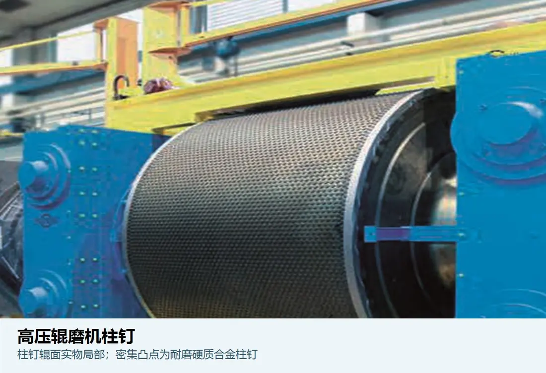
HPGR Roll Studs
Cemented carbide elements for studded roll surfaces · Identify by dimensions, end profile and bores
Studs cannot be specified by diameter alone. ANRANST checks carbide materials, dimensions and end geometry, substrate bores, retention methods, stud loss and fractures for drawing review, quality control and finished-product delivery. Interference-fit and pressing requirements apply only to the corresponding drawing-defined construction.
Part Function Dimensional identification Diameter, overall length, effective length, end profile, radii and chamfers Material identification Hard phase, binder phase, microstructure, density and transverse rupture strength Assembly identification Substrate bore diameter, surface condition, interference fit, pressing and protrusion Position Identification Centre, transition and edge zones, and stud layout drawing
Form a wear-resistant working layer together with the roll substrate
Studs sit in bores in the roll substrate and withstand abrasion, contact stress and cyclic impact in the high-pressure material bed. Material retained between studs can help protect the substrate; its effectiveness depends on stud layout, protrusion, feed, pressure and stable operation.
Similar appearance does not establish interchangeability. Diameter, effective length, end radii or taper, chamfers, surface condition, bores and interference together determine assembly and service reliability.
Position and Performance
Check studs, substrate bores and the material bed as a system
Increasing stud hardness alone does not resolve stud loss, fracture or substrate cracking.
Central high-pressure zone
Under relatively steady contact pressure and abrasion, record stud wear, protrusion, retained material and substrate exposure.
Edge transition zone
Pressure gradients, uneven flow and edge structures affect this zone. Record stud loss, uneven wear and local fractures separately for each end.
Stud-to-bore fit
Bore diameter, roundness, roughness, interference and pressing procedure determine retention. A damaged bore requires assessment before fitting another stud of the same size.
End geometry
Radii, taper, chamfers and effective lengths at the working and insertion ends affect stress concentration and location.
Cemented carbide microstructure
Hard-phase grain size, binder content and microstructural uniformity affect wear resistance, toughness and fracture behaviour. Verify them against operating conditions and drawings.
Replacement set scope
Organise sets by roll surface layout, zone and quantity. Record batch, position and installation data for subsequent service-life comparisons.
Materials and Manufacturing Processes
Tungsten carbide and the metallic binder jointly determine performance
Confirm composition, hardness and service-life assessments against drawings, material inspection and field wear records.
Selection sequence: ore and pressure → stud loads and wear → carbide system → substrate bores and assembly → batch inspection → service-life records by position.
Failure Diagnosis
First distinguish normal wear, stud loss, fracture and substrate damage
Each condition has different potential dimensional, material and assembly causes.
| Observed condition | Priority checks | Improvement Options |
|---|---|---|
| Uniform loss of stud length | Ore abrasiveness, pressure, speed, protrusion, retained material and carbide system | Compare wear by zone, then optimise materials and replacement intervals |
| Complete stud loss | Bore diameter, roundness, interference, bore-wall damage, pressing records, temperature and operating impact | Repair or restore bores and control interference fits and assembly |
| Working-end fracture or chipping | End profile, stress concentration, toughness, inclusions, foreign-object impact and local uneven loading | Check end geometry and material toughness, and improve control of foreign objects and uneven loading |
| Early fracture across a batch | Raw materials, compaction and sintering, microstructure, density, internal defects and batch inspection | Trace the batch and strengthen acceptance checks for microstructure, dimensions and mechanical properties |
| Substrate cracking around studs | Bore spacing, edge distances, interference, pressing loads, substrate properties, residual stress and hardfacing heat effects | Assess studs and substrate together before increasing stud strength |
Drawings and Inquiry Details
Identify studs by roll surface layout, dimensions, material and bores
Use a reliable drawing where available. Otherwise provide an approved sample, dimensional report and the corresponding roll surface position.
Equipment and roll surface
OEM, full model, serial number, fixed/floating roll, roll surface structure and modifications.
Stud dimensions
Diameter, overall and effective lengths, geometry at both ends, radii, chamfers, surface and geometric tolerances.
Bores and assembly
Bore diameter and depth, roundness, roughness, interference, pressing direction, protrusion and layout drawing.
Drawing or sample and batches
drawing, customer model details, revision, project number, batch and used-part markings.
Materials and inspection
Material system, microstructure, density, properties, dimensions, appearance and batch sampling requirements.
Operating Conditions and Failure Modes
Ore, pressure, speed, throughput, service life, stud loss rate, fracture locations and site photographs.
Related Equipment and Parts
Connect studs with roll surface assemblies, OEM installations and materials
This page covers stud dimensions, materials, bores and failures. Use OEM equipment pages to identify the installed series and roll surface structure.
HPGR Roll Surfaces and Sleeves Review the roll surface assemblies, flanged rolls and working-layer structures that incorporate studs. General High Pressure Grinding Rolls Information Review the fixed roll, floating roll and material-contact positions. Metso HRC / HRCe Check HRC / HRCe models, roll diameter and width, and installation arrangements. FLS HPGR Identify studs and roll surfaces through the FLS equipment series. thyssenkrupp Polysius HPGR Check roll surface structures and drawing through the brand's equipment series. Cemented Tungsten Carbide Review carbide materials, properties and inspection requirements.
ANRANST is an independent wear-parts engineering team. OEM names and trademarks belong to their respective owners. Confirm the full model, serial number, drawings, dimensions and actual operating conditions before manufacture.