
HPGR PRESS FRAME / FRAME WEAR LINER
HPGR Frame Protection Liners
Replaceable protection inside the frame, near roll ends and below rolls · Identify by location and plate number
Frame protection liners shield the machine structure from wear caused by flying material, falling feed, scraping and buildup. ANRANST checks frame zone, fixed or floating roll side, orientation, plate number, profile, hole pattern, material, used-part wear and drawing, distinguishing structural supports from replaceable wear plates.
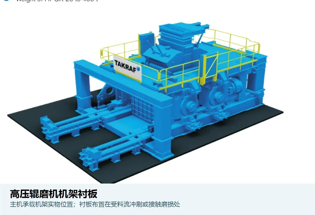
System function Zone identification Roll ends, below rolls, inner sidewalls, near crossmembers or at discharge transitions Orientation identification Fixed/floating roll side, drive/non-drive end, left/right Geometry identification Profile, thickness, hole pattern, bends, recessed holes and mounting datums Connection identification Bolts, clamping plates, shims, welded parts and rear support
Use replaceable plates to protect the main frame structure
Frame liners provide a maintainable sacrificial layer that prevents material from wearing the frame, supports, crossmembers or nearby structures directly. Duty varies by location, so material selection must address each installation zone.
Rear support, flatness, hole positions and fastening condition affect vibration, warping and hole-area damage. Inspect the frame mounting surface for wear when replacing plates.
Position and Performance
Consider protective coverage, maintainability and frame datums together
Assess existing frame damage before covering the area with a replacement liner.
Roll-end material-splash zone
Exposed to material carried by the rolls, lateral escape and fast-moving particles. Check local grooves, edges and joints.
Falling-material zone below the rolls
May experience impact from cake or particles. Check support beneath the plate, effective thickness and impact toughness.
Inner frame sidewalls
Mainly subject to abrasion, scraping from buildup and cleaning damage. Check coverage and modular replacement arrangements.
Areas near moving parts
Near floating rolls, hydraulic systems or adjustment mechanisms, verify the full movement envelope and safe clearances to prevent interference.
Mounting surfaces and support
Plate shape, rear contact, hole positions and shims affect loading. Unsupported areas increase vibration, cracking and bolt loosening.
Inspection and replacement access
Record remaining thickness and frame substrate condition by position number, and verify that replacement restores the design datums.
Materials and Manufacturing Processes
Establish support, plate shape and connections before increasing surface wear resistance
Confirm grade, hardness, thickness and service-life targets using drawings, used parts and operating conditions together.
Material options: Hardox 500, chromium carbide overlay plate and high-chromium cast iron KmTBCr26 are material candidates for assessment. Confirm hardness for the product thickness and material standard; suitability for frame protection depends on impact, support and drawing requirements.
Material options are for preliminary engineering selection; suitability and service life depend on the application.
Selection sequence: flying material, falling feed and buildup → wear and impact by zone → plate and support failures → materials and structure → drawings and inspection → mounting datums → service-life records.
Failure Diagnosis
Distinguish plate wear, fastening failure and main frame damage
Assess substrate wear or cracks before installing a new liner over the affected area.
| Observed condition | Priority checks | Improvement Options |
|---|---|---|
| Local wear-through or grooving | Material path, direction of flying material, coverage, material, thickness and adjacent joints | Extend protection or optimise materials for high-wear zones |
| Liner cracking or warping | Impact, support beneath the plate, plate shape, heat effects, hole edges and material toughness | Restore support and control manufacturing and installation distortion |
| Bolt loosening or tearing around holes | Preload, contact surfaces, hole pattern, locking, vibration, buildup and maintenance records | Restore mounting surfaces and standardise fastening procedures |
| Contact between liners and moving parts | Floating roll travel, hydraulic movement, plate orientation, deformation and safe clearances | Recheck profiles and positions over the full travel range |
| Main frame wear or cracks | Liner coverage, remaining thickness, mounting surfaces, previous repairs and structural stresses | Assess the main structure first and establish a controlled repair procedure |
Drawings and Inquiry Details
Identify parts by frame zone, plate number, outline and mounting datums
Record confirmed drawing and customer model details together. Manufacture to the controlled drawing revision.
Equipment and frame
OEM, full model, serial number, frame version, roll surface design and modifications.
Location and plate number
Fixed/floating roll side, drive/non-drive end, above/below rolls, left/right orientation, plate number and quantity.
Outline and hole pattern
Length, width, thickness, bends, profile, hole diameters and spacing, recesses, joints and mounting datums.
Mounting surfaces and clearances
Rear support, shims, clamping plates, fasteners, minimum clearance to moving parts and frame substrate condition.
Drawing or sample and materials
drawing, customer model details, revision, material, hardness and manufacturing process.
Operating conditions and service life
Feed material, throughput, flying- and falling-material locations, remaining thickness, failure photographs and replacement records.
Related Equipment and Parts
Connect frame liners with HPGR equipment, adjacent wear parts and OEM installations
This page covers general protection zones, materials and failures. Use OEM equipment pages to confirm series, model and frame version.
General High Pressure Grinding Rolls Information Review the relationship between the frame, fixed roll, floating roll and discharge path. HPGR Discharge Chute Liners Check the discharge wear system adjacent to frame protection below the rolls. HPGR Side Liners and Cheek Plates Distinguish material-bed containment beside the roll gap from frame protection plates. Metso HRC / HRCe Check HRC / HRCe models, frames and protection zones. FLS HPGR Identify frame protection drawing through the FLS equipment series. thyssenkrupp Polysius HPGR Check frame plate positions through the brand's equipment series.
ANRANST is an independent wear-parts engineering team. OEM names and trademarks belong to their respective owners. Confirm the full model, serial number, drawings, dimensions and actual operating conditions before manufacture.