
HPGR EDGE PROTECTION / EDGE SEGMENT
HPGR Roll Edge Protection
Replaceable wear parts for roll edges and flanged roll ends · Identify by roll type, end and segment
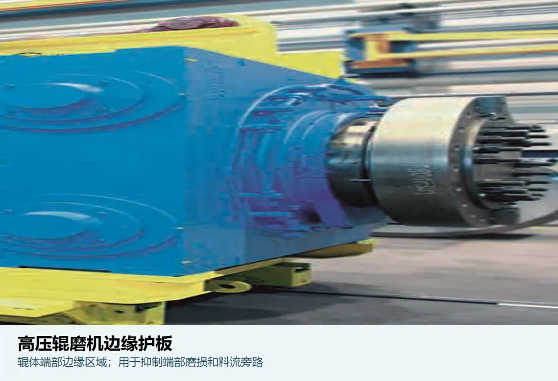
Edge protection withstands steep wear gradients at roll edges and protects the roll-end structure. Parts may be bolted flange edge segments or separate edge blocks in other roll surface systems. Identify the roll design first and distinguish these parts from frame-mounted cheek plates.
Part Function Roll type identification Flanged roll, studded roll or other replaceable edge design Roll-end identification Fixed / floating roll, drive / non-drive end Segment identification Segment count, circumferential position, start and end angles, and joints Connection identification Bolt holes, locating surfaces, clamping plates, keyways and preload
Resist roll edge wear and maintain the working profile
Pressure, material flow and wear at HPGR roll edges differ from those in the centre. Replaceable edge parts restore the edge profile, protect the roll end or flange, and work with the roll surface and cheek plates to contain material at the edges.
Similar-looking curved segments can have different inner and outer diameters, arcs, thicknesses, hole patterns, end-face angles and installation orientations. During inspection, record each part's roll, end, segment number and rotation direction.
Structure and Performance
Edge segments, roll surfaces and cheek plates form the edge protection system
Identify the part's structural location before assessing material, service life and replacement scope.
Flanged roll edge segments
Replaceable segments mounted at the flanged roll edge. Check the end position, arc, joints, bolted connections and working-surface height.
Separate edge blocks
Individual protection parts mounted at the tyre or roll surface edge. Identify them by their seats, attachment method and adjacent working layer.
Edge working profile
Effective height, slopes, radii and transitions determine material containment and clearance to cheek plates.
Bolts and location features
Hole patterns, recesses, locating surfaces, fastener preload and locking measures affect segment stability and seat life.
Adjacent roll working layer
Match edge segment height and wear progression to the centre of the roll surface to avoid steps, interference or local uneven loading.
Position control for complete sets
Organise sets by roll, end and circumferential segment number, and record each part's wear, cracks and replacement history.
Materials and Manufacturing Processes
Balance wear resistance, impact resistance, connection reliability and dimensional stability
Confirm composition, hardness, dimensions and service-life assessments against drawings, material inspection and field wear records.
Selection sequence: roll surface design and feed → edge pressure and wear → segment profile and connection failures → materials and processes → dimensional and non-destructive inspection → service-life records by position.
Failure Diagnosis
Distinguish normal wear, chipping, loosening and seat damage
Analyse edge part failures together with adjacent roll surfaces, cheek plates and feed conditions.
| Observed condition | Priority checks | Improvement Options |
|---|---|---|
| Rapid loss of working-surface height | Ore abrasiveness, edge flow, pressure distribution, profile, material and adjacent roll surface height | Record wear by roll end and match materials and profiles |
| Corner chipping or through-fracture | Foreign-object impact, stress concentrations, hole edges, seat support, material toughness and internal defects | Improve radiused transitions and support, and strengthen manufacturing and non-destructive inspection requirements |
| Bolt loosening or hole-area damage | Preload, contact surfaces, hole tolerances, locking, vibration and thermal cycling | Restore locating surfaces and fastening procedures, and inspect seat damage |
| Widening segment joints or steps between segments | Segment dimensions, installation sequence, circumferential location, fastening and adjacent segment wear | Reassemble to the complete segment layout and check joints |
| Cracking of the seat or roll end | Assembly interference, excessive preload, residual stress, hardfacing heat effects and uneven operating loads | Assess roll-end structural integrity before replacing further segments |
Drawings and Inquiry Details
Identify parts by roll type, end, segment and connection design
Record confirmed drawing and customer model details together. Manufacture to the controlled drawing revision.
Equipment and roll type
OEM, full model, serial number, roll diameter and width, roll surface system and modifications.
Position and Direction
Fixed/floating roll, drive/non-drive end, circumferential segment number, rotation direction and quantity.
Profile and hole pattern
Inner and outer diameters, arc, length, thickness, height, slopes, hole diameters and spacing, recesses and locating surfaces.
Adjacent parts and connections
Adjacent roll working layer, cheek plate clearance, bolts, clamping plates, shims and seat condition.
Drawing or sample and materials
drawing, customer model details, revision, material, heat treatment and inspection requirements.
Operating Conditions and Failure Modes
Ore, pressure, throughput, service life, wear curves, fracture or loosening locations, and site photographs.
Related Equipment and Parts
Connect edge parts with roll surfaces, cheek plates, OEM installations and materials
Identify edge parts and cheek plates separately using their respective installation positions and drawing.
HPGR Roll Surfaces and Sleeves Review the flanged roll, studded roll and working-layer structures surrounding the edge parts. HPGR Side Liners and Cheek Plates Check the frame-mounted plates adjacent to roll-end edge parts. General High Pressure Grinding Rolls Information Review the relationship between the fixed roll, floating roll, roll ends and material bed. Metso HRC / HRCe Check HRC / HRCe series, flanged rolls and edge segment installation arrangements. FLS HPGR Identify edge components and drawing through the brand's equipment series. thyssenkrupp Polysius HPGR Check roll edge structures through the relevant brand's equipment series.
ANRANST is an independent wear-parts engineering team. OEM names and trademarks belong to their respective owners. Confirm the full model, serial number, drawings, dimensions and actual operating conditions before manufacture.