
BALL MILL TRUNNION
Ball Mill Trunnions
Large Rotating Load-Bearing Parts · Confirm Journal, Flange, Bore and End Position Separately
The trunnion connects the mill head, main bearing and feed or discharge passage. It carries the rotating load and provides the bearing journal surface. ANRANST offers end-position and drawing identification, assessment of materials and manufacturing methods, NDT and dimensional quality control, and delivery to drawing.
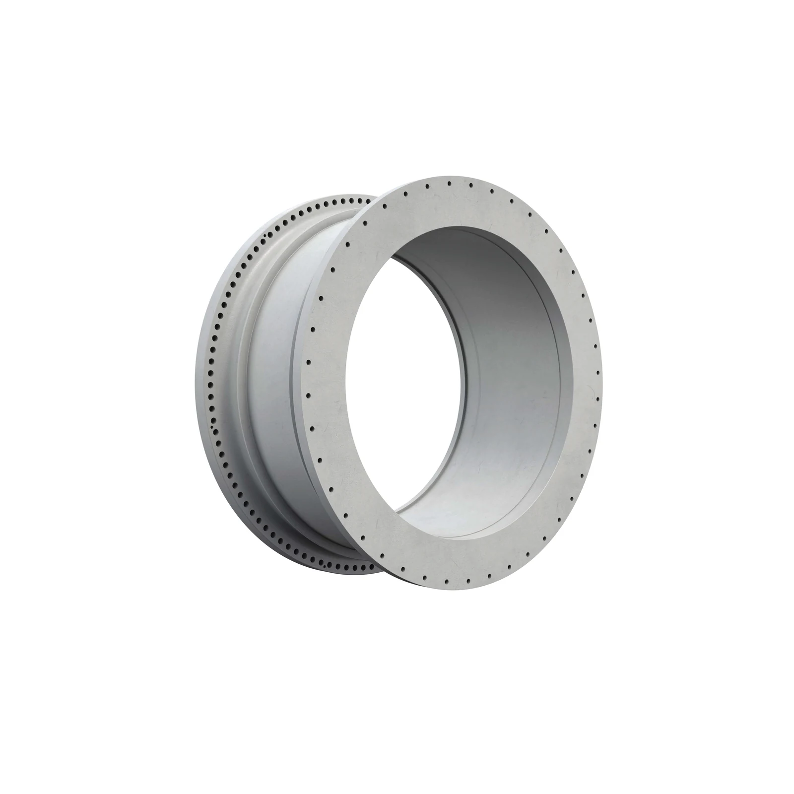
Part scope Head Connection Flange Transfers loads and defines the hole pattern and mating face Load-Bearing Journal Forms the sliding bearing interface with the bearing liner or support pads Bore and Liner Fit Locates the replaceable liner and isolates the trunnion from process material Sealing and End Interfaces Connect to the feed, discharge, trommel or sealing system
The Trunnion Carries Load; the Bore Liner and Bearing Liner Serve Different Functions
The trunnion flange connects to the mill head, the main bearing supports the journal, and a trunnion liner fits in the bore to form the feed or discharge passage. Although assembled together, these parts have different materials, functions, dimensions and acceptance requirements.
For trunnion supply, establish whether it is separate from or integral with the head. Check the journal, flange, bore, seal grooves, liner fit and transport and lifting interfaces together.
Position and Performance
Control Structural Strength, Journal Surface, Flange Connection and Bore Fit Together
A large trunnion cannot be reproduced from appearance or a single dimension. Check the load path and all adjoining interfaces.
Journal Running Surface
Mates with the main bearing liner or support pads. Check diameter, roundness, cylindricity, roughness, hardness and surface defects.
Head Connection Flange
Transfers mill shell loads. Check the mating face, locating register, hole pattern, pitch circle, preload, coaxiality and connection stiffness.
Bore and Liner Interface
Accommodates the trunnion liner. Check bore diameter, taper or steps, fit, grouting, retaining rings and local wear.
Transition Fillets and Section Changes
Transitions between the journal, body and flange experience cyclic stresses. Inspect fillets, defects, machining marks and cracks.
Seal Grooves and Bearing Interfaces
Affect separation of lubricant and slurry. Check groove wear, sleeve repairs, seal position and bearing housing interfaces.
Locating and Floating End Functions
The locating end provides axial location, while the floating end accommodates thermal expansion. These functions must match the bearing system and end-position drawings.
Materials and Manufacturing Methods
Specify Casting Material, Internal Quality, Heat Treatment and Machining Together
Metso mill parts literature lists ductile iron trunnions. Other OEMs or legacy models may use different materials or integral designs; confirm against the drawings.
Establish grade, composition, mechanical properties, heat treatment, weld-repair rules, non-destructive inspection levels, dimensional tolerances and surface requirements through drawings and technical agreements. Images alone cannot identify the material.
Failure Diagnosis
Assess Cracks, Journal Wear and Fit Damage Alongside Loads and Adjacent Systems
When damage is found, also inspect the head, bearings, liners, seals, alignment and operating records.
| Observed condition | Priority checks | Improvement Options |
|---|---|---|
| Cracks at Transition Fillets or Flanges | Loads, fillets, casting defects, machining marks, hole patterns, preload, alignment and abnormal impacts | Assess material and cracks, and restore load paths and interfaces |
| Journal Scoring, Uneven Wear or Dimensional Nonconformity | Bearing liner, oil film, contamination, alignment, roundness, taper, surface condition and locating or floating end function | Repair the journal, bearing, lubrication and sealing systems as a coordinated assembly |
| Wear at the Bore and Liner Interface | Loose liners, fasteners, grouting, material flow, bore dimensions and remaining trunnion section | Restore the locating surfaces and confirm the liner construction |
| Seal Groove Wear, Oil Leakage or Slurry Ingress | Groove surfaces, sleeves, seals, axial movement, bearing housing, lubrication and contamination records | Restore sealing surfaces and axial position, and control sources of contamination |
| Flange Hole Damage or Face Runout | Hole pattern, preload, locating register, flange face, transport and lifting, assembly sequence and head distortion | Restore locating surfaces, hole geometry and flange connection quality |
Drawings and Inquiry Details
Identify the Trunnion by End Position, Assembly, Critical Dimensions and Drawing Revision
Provide the drawing, third-party model details or customer part reference, and confirm it against the end position, installation drawings and revision.
Equipment identification
OEM, series, complete model, serial number, shell diameter, EGL, power, speed and modification history.
End Position and Assembly
Feed or discharge end, locating or floating end, separate or integral head design, quantity and position number.
Drawing and Revision
Trunnion drawing, head assembly number, drawing, spare model details, drawing revision, project number and physical markings.
Journal and Bore Dimensions
Journal diameter and width, roundness, taper, roughness, bore diameter, overall length, wall thickness, steps and fits.
Flange and Adjacent Interfaces
Flange outside diameter, locating register, mating face, hole diameters, hole spacing, pitch circle, head, liner, bearing, seals and trommel.
Materials and inspection
Material, heat number, heat treatment, mechanical properties, casting records, UT/MT/PT, dimensional reports, cracks and repair history.
Related Equipment and Parts
Match the Trunnion to Its Liner, Main Bearing, Mill and OEM Installation
The general parts page defines the part and its manufacturing requirements. OEM pages identify the equipment series. Drawings, dimensions and inspection requirements complete technical confirmation.
Trunnion Liner Check bore protection, fits and the feed or discharge passage. Main Bearings, Bearing Liners and Housings Check the journal, oil film, locating or floating end and seals. General Ball Mills Information Review the relationship between the head, trunnion, bearings and feed or discharge systems. Metso Select / Premier Ball Mills Check series, dimensions, end positions and installation drawing. FLS Ball Mills Start trunnion identification with the equipment brand, series and installation records. Materials, Manufacturing and Inspection Review large casting materials and quality-control requirements.