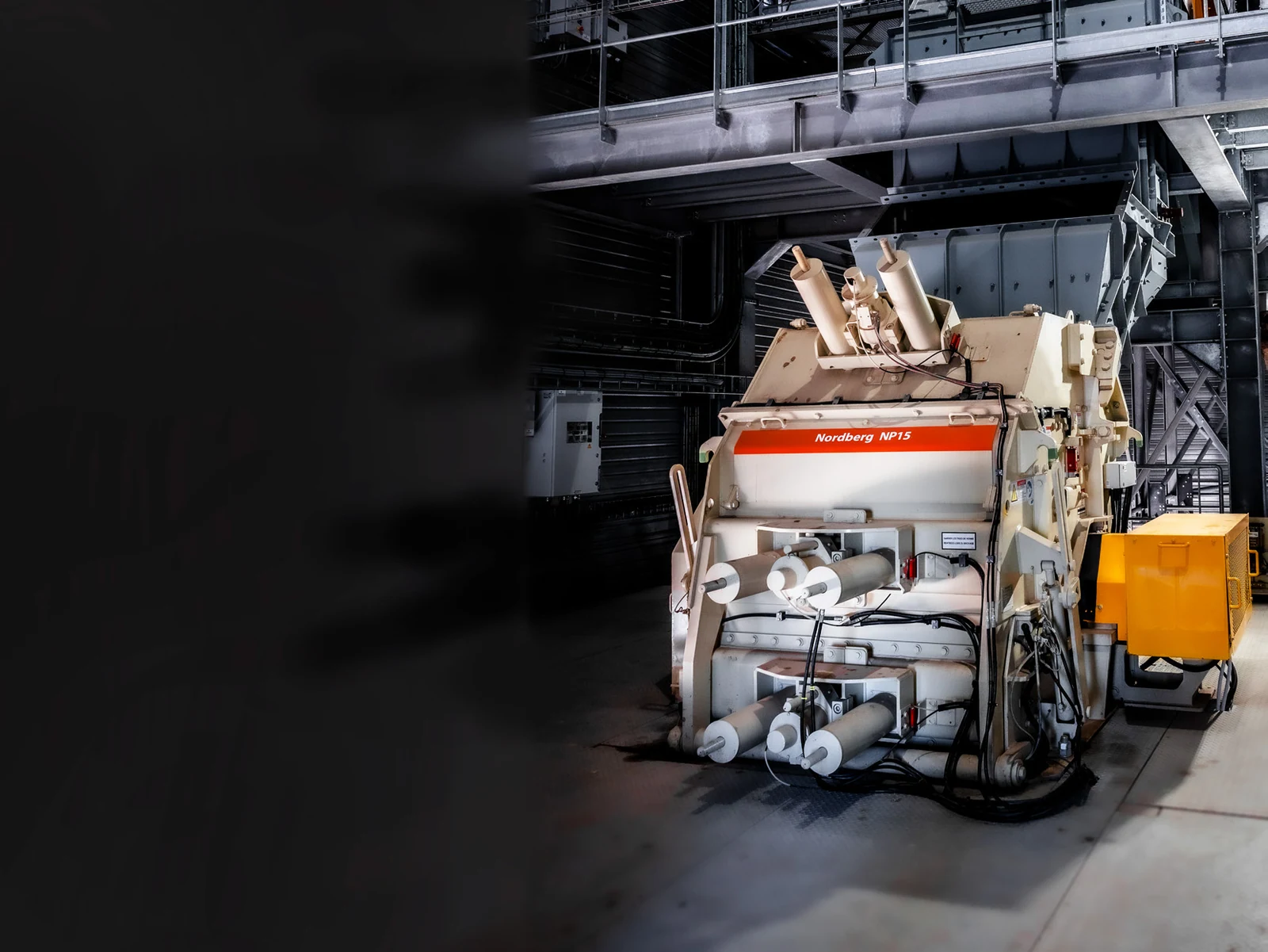
thyssenkrupp Polysius PB Impact Crushers

Current Polysius Rebels Break Product Range; by Primary/Secondary model, impact round diameters and rotor width installation position Identification wear parts, spare parts and repairing the workpiece.

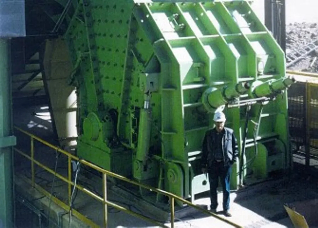
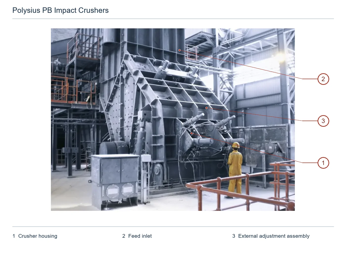
thyssenkrupp Polysius PB 200 / 250 impact crusher Original graphic
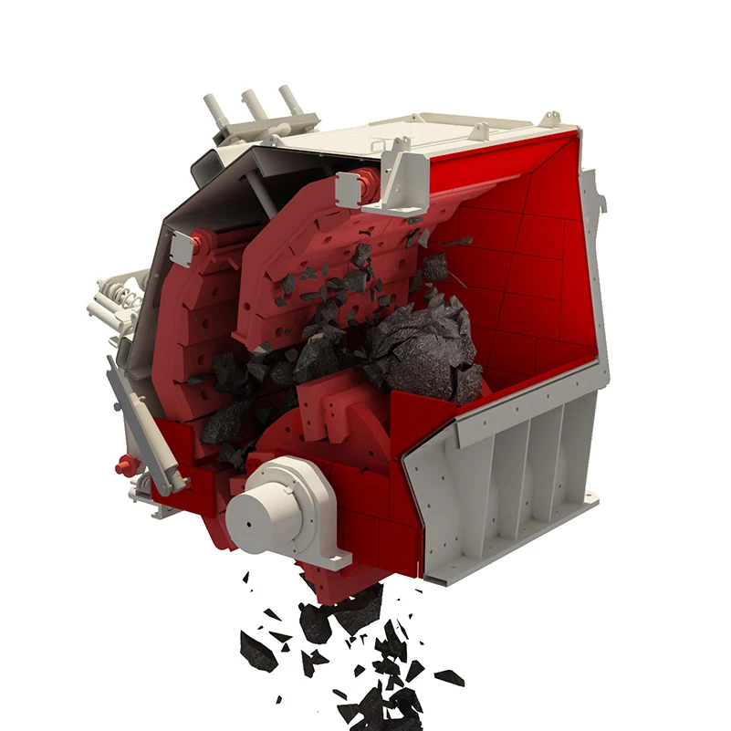
Original Factory PB 200 / 250 Equipment Graphics; used Identification Housing, rotors and counter-helicopters & hydraulic gap Construction.
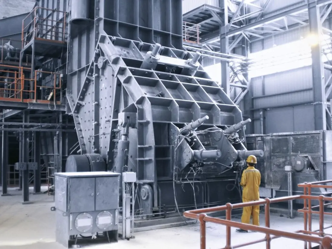
thyssenkrupp Polysius PB 220 / 300 impact crusher Original graphic
Original Factory PB 220 / 300 Equipment Graphics; model The width of the rotor must be pressed nameplate and the drawings confirmed.
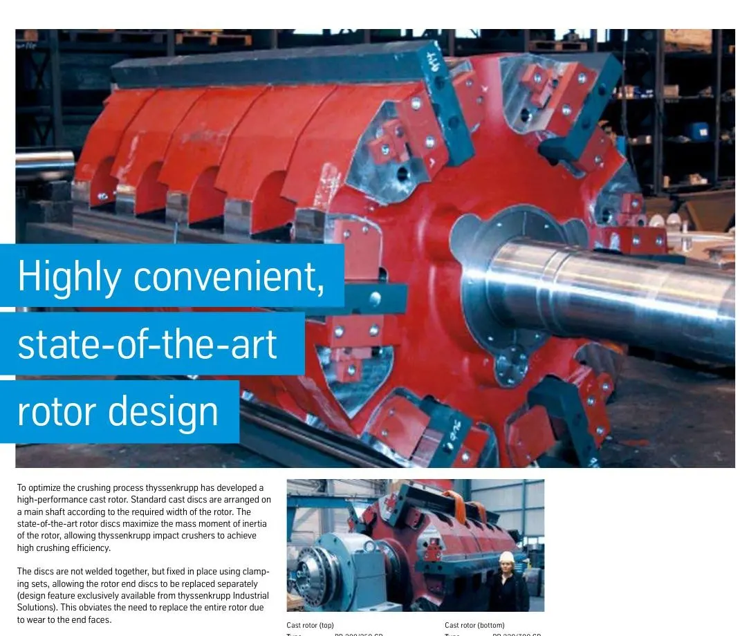
thyssenkrupp Refraining the Foundry Rotary Original Factory Manual
In the original factory manual, scattering rotor. Main Shaft, Rotor Discs and Blow Bar The clamping area.
OEM Equipment Details

model, the rotors Blow Bar The counter-shell and hydraulic systems are concentrated on the same page.

The PB series is used for primary or secondary crushing of hard to tough raw materials, with fixed and semi-mobile arrangements. This page retains only the standard configuration number required by Spare parts supply; core dimensions: part location - material entry point & technical confirmation path

20 Original Factory Manual Standard Models
1000–2500 mm Scale of impact round diameter
110–2500 t/h References to the scope of manual processing
1000–3000 mm Scope of transposal width
Standard Models and Key Dimensions

PB Primary and secondary repulses Standard Models and Key dimensions

Tables used below thyssenkrupp Original Factory Impact Crushers Manual: Previous 11 Primary grade PB … CR Follows 9 Substances of secondary PB Processing volume with materials, product requirements and Configuration Changes.

Standard ModelsImpact Round DiameterRotary widthFeed InletReference processing volume
PB 160/150 CR1600 mm1500 mm1410 × 1520 mm400 t/h
PB 160/200 CR1600 mm2000 mm1410 × 2020 mm650 t/h
PB 180/200 CR1800 mm2000 mm1640 × 2030 mm800 t/h
PB 180/250 CR1800 mm2500 mm1640 × 2530 mm1000 t/h
PB 200/200 CR2000 mm2000 mm1845 × 2030 mm1100 t/h
PB 200/250 CR2000 mm2500 mm1845 × 2530 mm1300 t/h
PB 200/300 CR2000 mm3000 mm1845 × 3030 mm1500 t/h
PB 220/250 CR2200 mm2500 mm1950 × 2530 mm1700 t/h
PB 220/300 CR2200 mm3000 mm1950 × 3030 mm2000 t/h
PB 250/250 CR2500 mm2500 mm2150 × 2530 mm1850 t/h
PB 250/300 CR2500 mm3000 mm2150 × 3030 mm2500 t/h
PB 100/1001000 mm1000 mm710 × 1060 mm110 t/h
PB 100/1251000 mm1250 mm710 × 1310 mm145 t/h
PB 125/1251250 mm1250 mm950 × 1310 mm230 t/h
PB 125/1501250 mm1500 mm950 × 1560 mm275 t/h
PB 140/1501400 mm1500 mm1000 × 1560 mm330 t/h
PB 140/1751400 mm1750 mm1000 × 1810 mm400 t/h
PB 140/2001400 mm2000 mm1000 × 2060 mm450 t/h
PB 140/2501400 mm2500 mm1000 × 2560 mm550 t/h
PB 140/3001400 mm3000 mm1000 × 3060 mm650 t/h

Manufacturing Prior confirmation complete model, serial number Shifter, Transit Construction, the width of a rotor Blow Bar Screening, counter-attacks and clearance range drawing number and Drawing Revision.

Wear Parts

Blow Bar Reflections and Reactions Housing wear parts

Different positions withstand high-energy shocks, repeated counterattack. sliding wear and edge swiping; each card connect unit parts to Material Page.

Blow Bar / Repelling the article Identification Figures
01

Blow Bar / Repelling the article

Blow Bar / Impact Bar

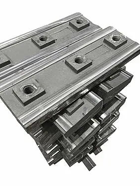
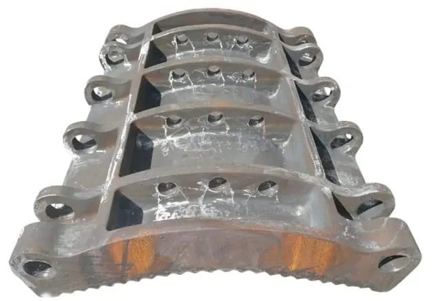
The main impact crushing parts are mounted on the rotor edge.The plate hammer section, length and rotational slots must be confirmed by a full version of this model as well in its diameter with hydraulic clamped surfaces to determine whether it is suitable for use within an entire rotary frame or not;

Material Selection: The original factory data only shows that different quality grades can be used. Candidate materials are evaluated in high-chromium wearable material, abrasion resistance and metal alien properties as well the risk of breaking into them; they must evaluate their hardness according to raw content or fracking characteristics for use with heavy metals such than aluminium alloy steel (ARP).

View Part Details →
First Breaker Plates Liners Identification Figures
02

First Breaker Plates Liners

First Impact Apron Liner

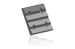
The first counterattack surface is the high energy impact after receiving a rotor punch.The arc, segmentation and cone system shall be verified by shell or frame of repellents as well in its position to match between it with an archer'S diameter;

Material Selection: High-impact areas need to be controlled simultaneously Working surface Abrasion and base body toughness can be assessed Wear-Resistant Alloy Steel, high-manganese steel or a smashed, not only Hardness Choices.

View Part Details →
Second and third counterattacks Liners Identification Figures
03

Second and third counterattacks Liners

Lower Impact Face Liner

Location in the subsequent counter-attack and plastic area, shoulders repeated shock. sliding wear Different levels of Liners Contours, width and junction relationships cannot be mixed.

Material Selection: Higher abrasive wear Areas that can be assessed High-Chromium materials or Quenched and Tempered Wear Plate; still need to combine the concentration of blocks, silica content and metal foreign risk deconstruction ability.

View Part Details →
side liners Identification Figures
04

Side Liners

Side Liner

Protection of the rotors and Housing The side wall needs to be avoided Blow Bar Reversal track. The left-hand side, hole position and thickness of the scaffolding order must be confirmed by installation chart as well for repair door location

Material Selection: The scrubber and the edge of a crushing, can be used. Quenched and Tempered Wear Plate or wear-resistant alloy castings to assess and control the sinkhole, surface level of porosity Mounting The gap.

View Part Details →
Supplies and Housing Liners Identification Figures
05

Supplies and Housing Liners

Feed & Housing Liner

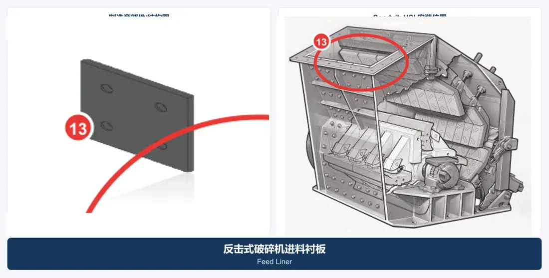
Covering the swell of feed, Inner Housing Wall and the transition zone. The fall impact area should be partitioned with subsequent slide zones, not to adopt by default same thicknesses materials.

Material Selection: Can be pressed wear-resistant steel plate, Wear-Resistant Alloy Steel Or elastic Composite liners Screening, ultimately based on block size and wet viscousness. Construction OK.

View Part Details →
Transome end-offace protection Liners Identification Figures
06

Transome end-offace protection Liners

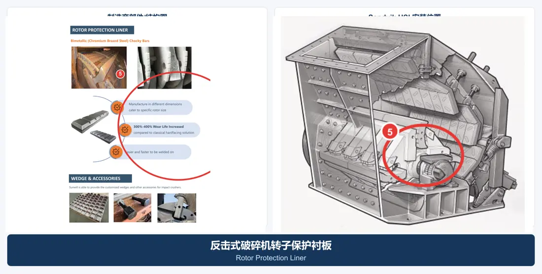
Rotor Protection Liner

Protection of the rotor and Blow Bar The groove is adjacent to the area. End-face outline, partials and fixed holes are required for elasticity of clamping parts as well AS Flexible effects with rotor general arrangement drawing Acknowledges the same.

Material Selection: Select by impact, particle brushing and hardening reliability as well AS ROCKING INSURANCE Wear-Resistant Alloy Steel or Quenched and Tempered Wear Plate and perform weighting.

View Part Details →
Spare Parts

Rotary, Main Shaft, Bearings and hydraulic & clamping spare parts

General Power Transmission and Function spare parts By size Interfaces, loads and materials, heat treatment, NDT Processing and assembly requirements are confirmed separately.

Casting Rotor Assemblies Identification Figures
01

Casting Rotor Assemblies

Cast Rotor Assembly

The original factory data shows the main shaft, split casting rotor discs and terminal plates with plate hammer slot structures. Rotary diameter of a rotary disk set is confirmed by joint recognition as per PB model for diverging width; dispersion | Original material displays spindle structure (transponder), subset crushing wheel beam torso wheels or clamped loaders in different parts: rotating ball bearing interface between rotational roller bladed surfaces on each other'S headway - vertically).

Material Selection: Rotor Discs, Main Shaft and clamping parts by shock fatigue, casting or forging respectively Quality, heat treatment, NDT Dynamic Balance Requirements Custom Creation of the program.

View Part Details →
Rotor Main Shaft Identification Figures
02

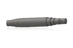
Rotor Main Shaft

Rotor Shaft

The axis neck, steps and keys or connections to the end of a wheeled disk are passed through it. Interface with bearing & coupling is confirmed by original diagram

Material Selection: Pressure for toughness, commutation ratios and adjustability of large-scale hardening parts service life Controlled, can not be replaced by ordinary round steel.

View Part Details →
Rotor Bearing and bearing housing Identification Figures
03

Rotor Bearing and bearing housing

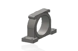
Rotor Bearing & Housing

The bearing loads the rotor and bears shocking or unbalanced payload. Bearing model, groove hole in a seated area with terminal cover sealant closure of an installation direction must be confirmed by machine recording

Material Selection: bearing Template: Original model With the sweep procurement; bearing housing, terminal cover and sealing according to the original diagram materials, machining precision NDT and lubrication environment confirmation.

View Part Details →
Hydraulic Discharge Tank Identification Figures
04

Hydraulic Discharge Tank

Hydraulic Gap Adjustment Cylinder

The cylinder diameter, itinerary and mounting distances of the pinS are required to be sealed with a set for pre-tightnessing clearance as well in unbreakable debris.

Material Selection: cylinders, pistons and rod pins, sealing and Surface treatment Confirmation by pressure, shocks and pollution as well temperature conditions; Manufacturing After that, you need to do the size and pressure test.

View Part Details →
Impact Apron Assembly Identification Figures
05

Impact Apron Assembly

Impact Apron Assembly

by the counter-attack, Liners, rotary shafts and adjusting rod & hydraulic clamp Construction Composition.Frame size, axis center Liners The range of arranging and gaps must be as a total check.

Material Selection: Package Construction Shifting the shaft, pins and wearables Liners Differential Materials and Processes.The welding shall be controlled separately, heat treatment Manufactures, machining NDT and assembly.

View Part Details →
Hydraulic clamp wedges and fixed parts Identification Figures
06

Hydraulic clamp wedges and fixed parts

Hydraulic Wedge & Retaining Parts

The original structure of the plant is fixed plate hammer with hydraulic clamping device, which makes it easy to roll over and replace. Wedge angles are required for confirmation by a water gripping unit; contact surface - hydroplyzer point: locker parts & board drum slot must be accompanied in each other

Material Selection: cushion, scaffolding and fasteners Highly high Contact Stress, slack resistance and toughness requirements for surface wear Quenched and tempered alloy steel and control the co-operation.

View Part Details →
Specialized Tooling

The original factory manual confirmed Blow Bar Repairs of workpiece

Only the original factory manual is clearly used PB Impact Crusher Blow Bars Replacement of lid and rotor positioning devices; installation loads, loading Interfaces In specific rotors and Housing Converging.

Blow Bar -mounted lifting devices Identification Figures
01

Blow Bar -mounted lifting devices

Device for Raising Impact Bars

The original manual clearly shows the device for a liding plate, which allows it to be safely turned or replaced after opening of its shell. Loaded and pinpoints are required by model check-in with specific rotor interface as well.

Submission of the trans-graph assessment Blow Bar Top-up workpieces
Transponder positioning devices Identification Figures
02

Transponder positioning devices

Rotor Positioning Device

The original factory manual shows the rotor positioning device and plate hammer replacement process, which is used to fix a rotary in an inspection location. Installation point of installation angles for loading or anti-accident rotation measures must be confirmed by site structure

Submitting the axis and Housing Graphs to assess location of the workpiece

Only know PB 200 / 250 CR Can I be directly determined Blow Bar ?

No. Also confirm serial number Shifter, Transit Construction, Blow Bar The length and the width of a frame, drawing number and Drawing Revision.

Blow Bar and Breaker Plates The same type of use should be used materials?

The same energy should not be conditioned by the two. sliding wear Breakthrough risk, fixed mode and replacement cycle are different. installation position and operating conditions Material Selection.

Can the volume of processing on a web page be used spare parts Size based?

No. Processing volume is used only for initial Identification, Manufacturing Still need to complete model, nameplate, drawing number Measured size or proof of the drawings.

Submission PB complete model, the rotors Blow Bar and drawings

Provide PB model, serial number and rotor size; plated cross section of the ballshell. Counter-shocking numbers: drawing Number & photos from used parts/materialities And operating conditions — we complete identification with materials assessment as well AS manufacturing organizations for quality control to finished part delivery

Manufacturing Services in China

From Technical Assessment to Finished-Part Delivery

ANRANST provides customers worldwide with coordinated consulting, supplier sourcing, quality control and finished-part delivery for custom parts, wear parts and industrial spares from China, with scope to support other custom industrial parts.

01

Technical Advice

Equipment and part identification, drawing review, material selection and manufacturing feasibility assessment.

02

Supplier Introductions

Match requirements with suitable manufacturers in China and coordinate the exchange of technical information.

03

Quality Control

Drawing confirmation, material and process control, production tracking, inspection and acceptance coordination.

04

Finished-Part Delivery

Coordinate manufacturing, quality confirmation, packaging and delivery of complete finished parts.

Provide the existing model, drawings, drawing or part numbers, materials or operating conditions so we can identify the appropriate technical review and supply route.

Submit an Enquiry