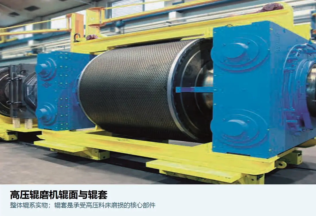
thyssenkrupp Polysius polycom® High Pressure Grinding Rolls

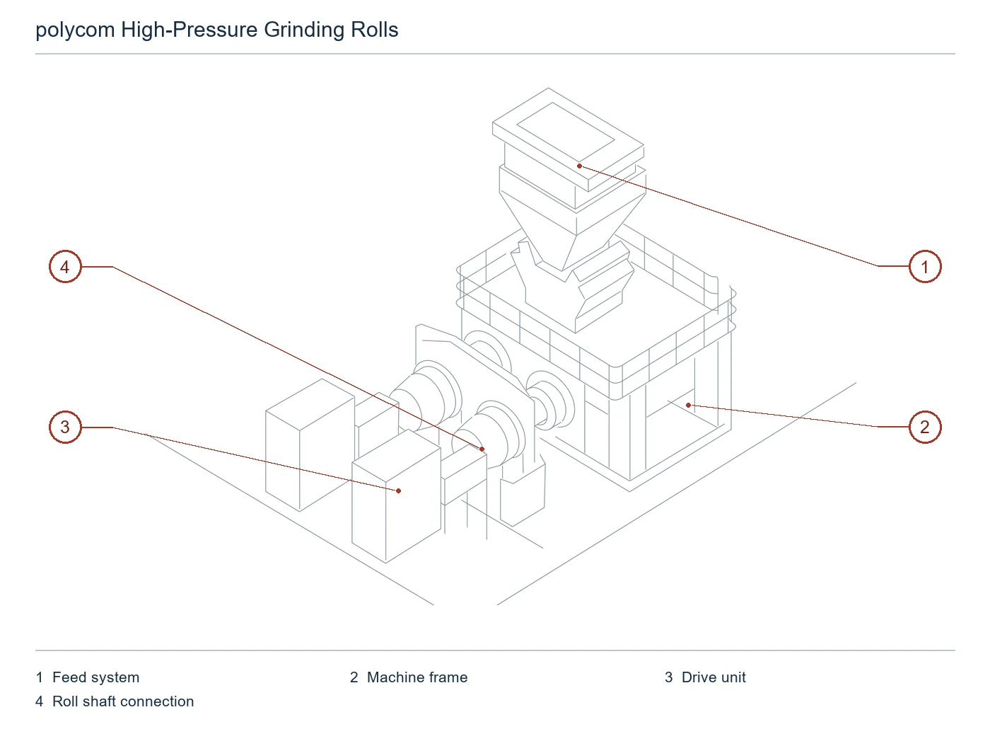
Current Polysius High-pressure bed milling Product Range; Configured by Project, Roll Forms of Body and Rope diameter/Roll width installation position Identification wear parts, bearing Hydraulics and drive spare parts.

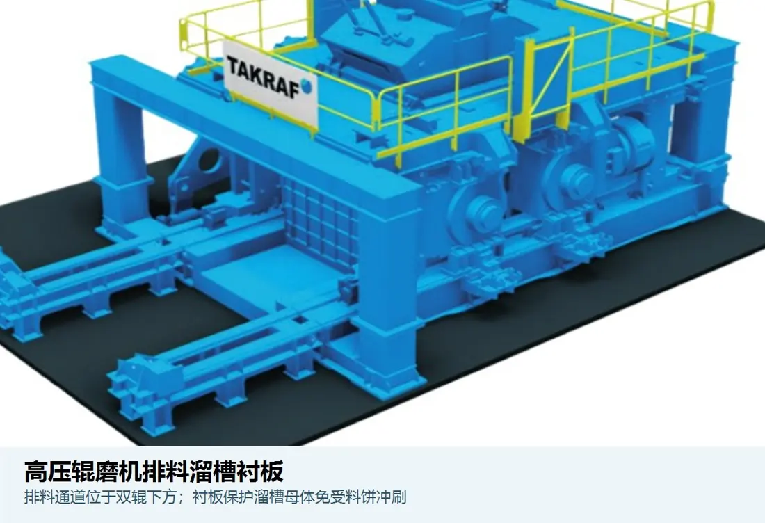
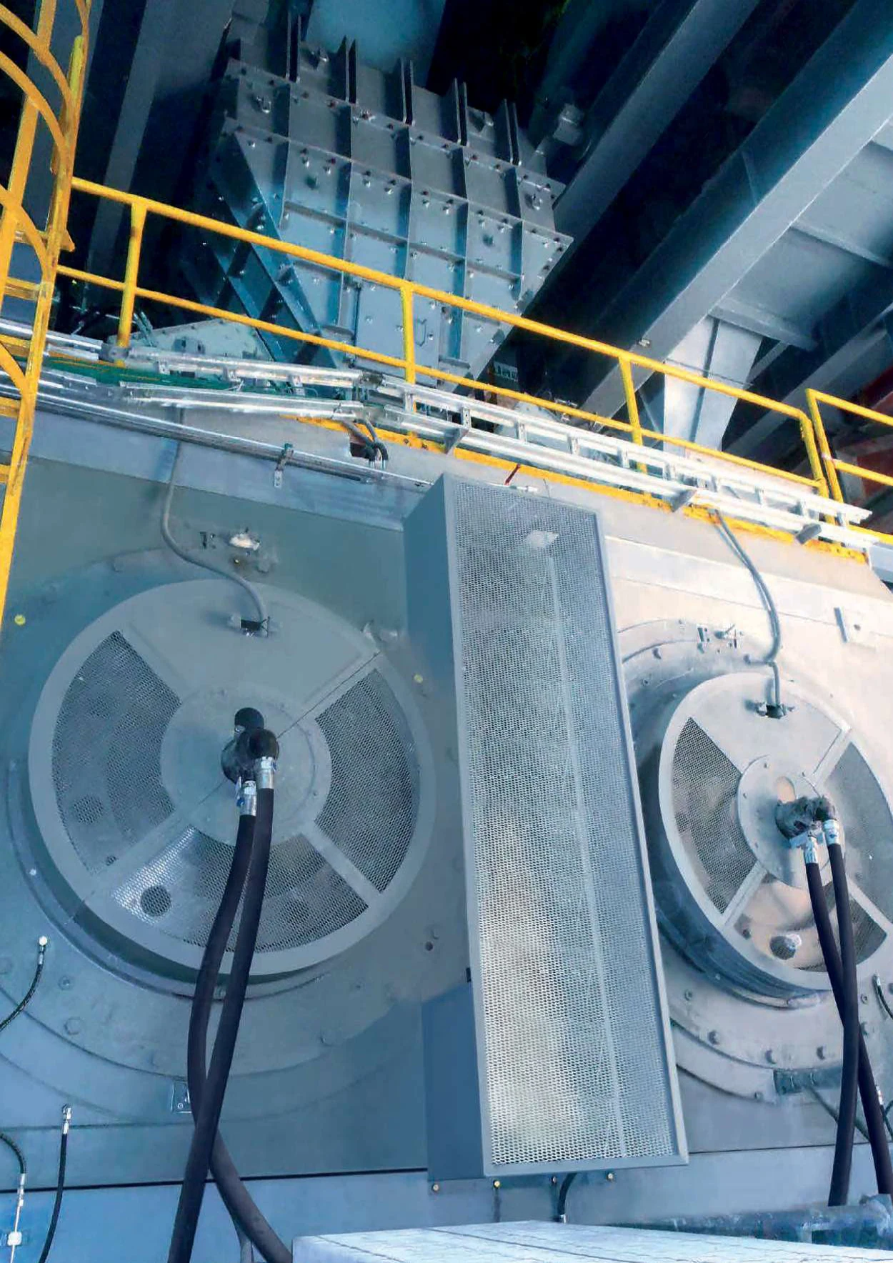
thyssenkrupp Polysius polycom HPGR Original Factory Equipment Figures
Original Factory polycom (r) Roller Units and Hydraulic Construction Figures for use Identification Fixed rollers, floating roll bearing and pressure systems.
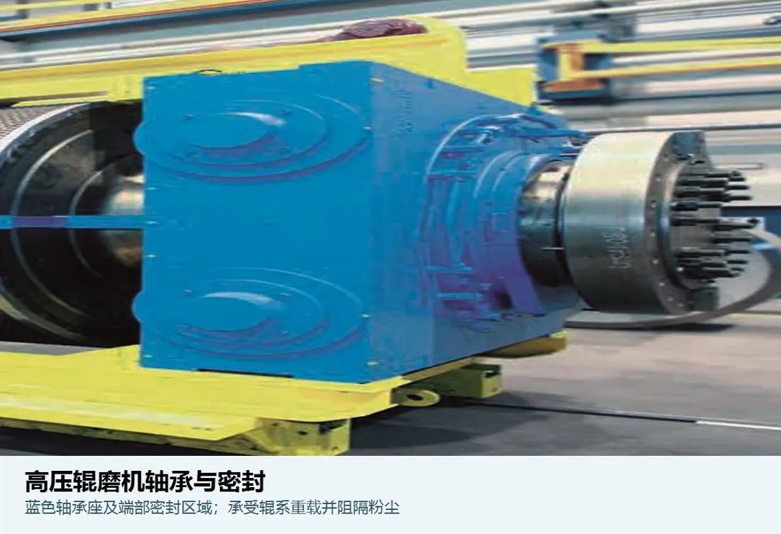
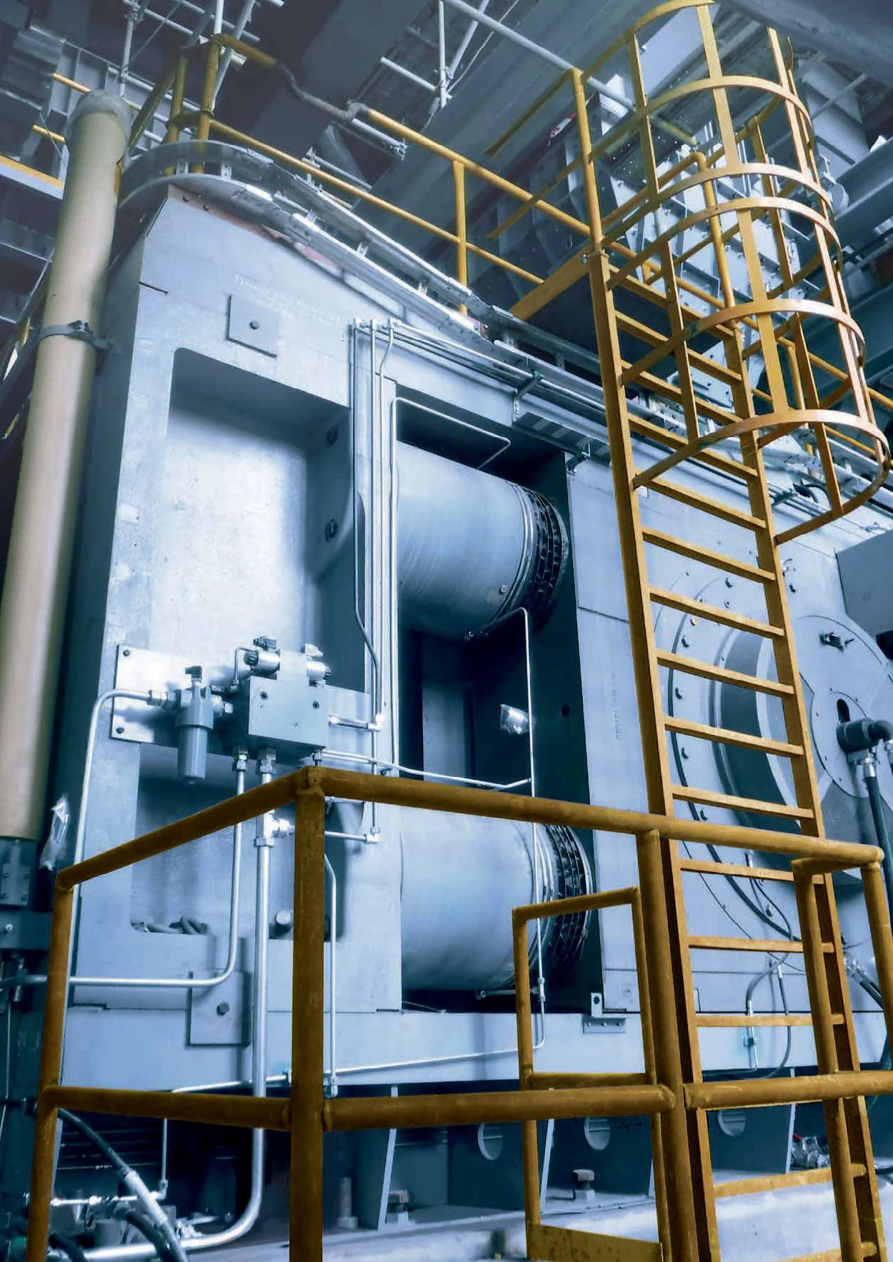
thyssenkrupp Polysius polycom bearing hydraulics and Roll Shafts Regional
The original factory view is visible Roll Shafts The endpoint, bearing housing, hydraulic cylinder and the rack area.
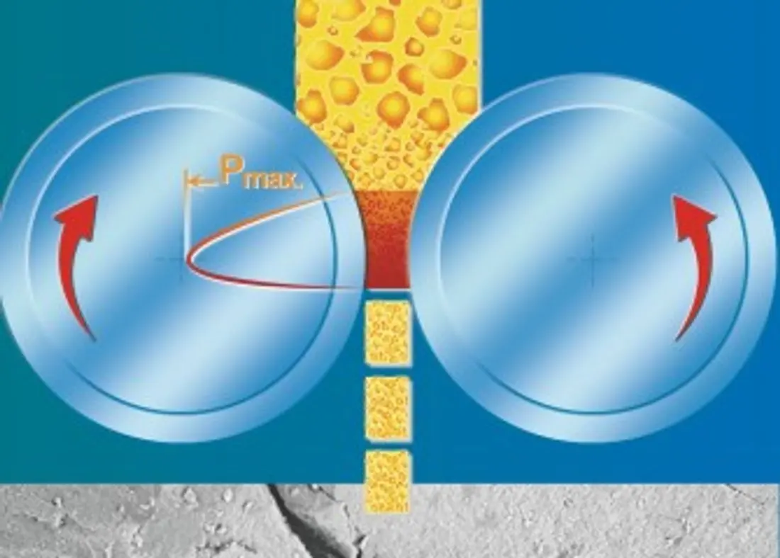
polycom High-pressure material bed smashing schematic
The principle of crushing the original high pressure material bed: two rollers are reversed, and materials in a roll stitch is subjected to heavy voltage compression.
OEM Equipment Details

Installer Configuration, Roller wear resistance system and key spare parts Concentrate on the same page

Polycom(r) is custom-made for materials, production and processes rather than single open model code. The public page provides configuration ranges of the layout sized by historical installation sizes as well roll body data that are directly related to Spare Part Identification so it can be easily confirmed using actual installed information on sparet parts

> 2000 t/h The current official website is the maximum capacity level.
≤ 60 mm The current official website opens the maximum feed granularity
Supreme Court 250 MPa Raw materials milling manual open roller slit pressure
3 Original factory open roller wear concept
Standard Models and Key Dimensions

polycom (r) Public Configuration and Installation Identification Scope

Current Official Site Existing Statement polycom (r) pressed Item Custom Undisclosed unification model Code; the table below lists only traceable currents Configuration and Historical Minerals HPGR Dimensional range.

Public Configuration / Mounting ScopeRoller diameters / Identification ScopeRollwidth / ConfigurationCapability and UseProduct Status
polycom (r) Raw Material Final Mill ConfigurationBy material and production Customby Item ConfidentialThe highest publicity capacity exceeds t/h.The maximum feed particle size mm (2000; 60)Current Products
polycom (r) Coal gel materials polishing ConfigurationBy cement clinker, slag etc. Customby Item Confidentialand sepol ® Classification System SuppliesCurrent Products
polycom (r) Pre-polishing/joint mill ConfigurationBy the existing ball milling system Customby Item ConfidentialFor expansion and energy-saving transformationCurrent Products
Polysius Minerals HPGR Loading range0.5 – 2.8 m Roller diameter0.2 – 1.8 m Rolling widthTo the Over t/h; × - × kW (20; 2500; 2; 50; 2; 3000)History Technology Scope of information

Manufacturing Prior confirmation nameplate, serial number, roller diameters and roll width; fixed/floatable rolling position. bearing Hydraulics, drive and drawing number and Drawing Revision.

Wear Parts

Roller, poles and sidebar with slot wear parts

Pressure, impact and wear mechanisms differ from the roller surface poles to roll end ends; materials and the process installation position Determinations separately.

Forged/heaped rollers Identification Figures
01

Forged/heaped rollers

Forged / Welded Roll Body

Roller surface stacking and rely on the material pad to form a natural wear resistance protection. The roller diameter, roll widths of scale welding type in bulk packaging moldings are required for corrugation by machine diagram as well with hard surfaces or edge structures that must be confirmed according their mounting profile

Material Selection: Roller cores, transition layers and hard surfaces are different Materials and Processes The system needs to be determined in combination with grinding, pressures and repair cycles as well.

View Part Details →
Composite Found Rollers Identification Figures
02

Composite Found Rollers

Compound-Cast Roll Body

The resistant body and high pressure external layer are designed for the operation of higher-than standard grinding conditions. External thickness, interfaces to surface surfaces or endpointing structures as well ASA systems must be confirmed by full roller unit

Material Selection: Composite castings need to control the core toughness, external pressure resistance wear and tear tolerance metallic combination. heat treatment and NDT, cannot be single Hardness Acceptance.

View Part Details →
cemented carbide Studded Roll Surfaces Identification Figures
03

cemented carbide Studded Roll Surfaces

Hard-Metal Studded Roll Surface

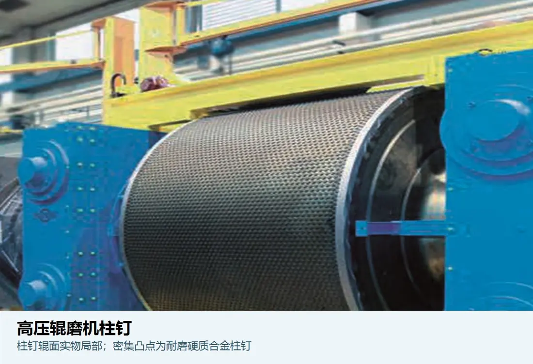
The nails and the roller surfaces form a self-made substrate protection, with diameter of pillars in line to length density; rowing.

Material Selection: nails used cemented carbide System; roller porosity area must balance strength, toughness and crack resistance. Mounting With replacement, over-control of the excess and hole walls Quality and protection of the edge.

View Part Details →
Sidebar / Cheekboard Identification Figures
04

Sidebar / Cheekboard

Cheek Plate / Side Liner

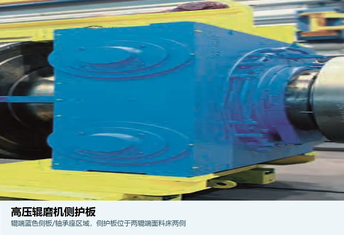
Restricting the material on both sides of a roller to escape and stabilize its column. Contours, thicknesses or gap areas (or margin), bearing positions in front-hand position as well for edge wear zones must be matched by roll diameter with width from rolling lines

Material Selection: Pressure high-pressure material lateral extrusion and grinding pellets to be evaluated wear-resistant steel plate, alloy steel Or compound reinforcement, and focus on controlling edge fracking with dimensions.

View Part Details →
Roller End Edge Protection Identification Figures
05

Roller End Edge Protection

Roll Edge Protection

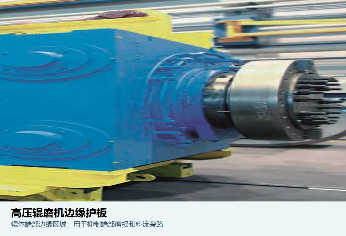
Protection of the high wear area in roller body end, reducing edge stripping and side leakage. Separations / fixed surface to be secured with a pin zone as well for right-handed roll positions must confirm by original figure

Material Selection: The edge zone shock, cutting and stress concentration is obvious. Resilient wear alloys can be used cemented carbide The nesting block or composite solution requires verification of the anti-collapse capability.

View Part Details →
Feed-chute liner identification image
06

Feed Chute Liner

Feed Chute Liner

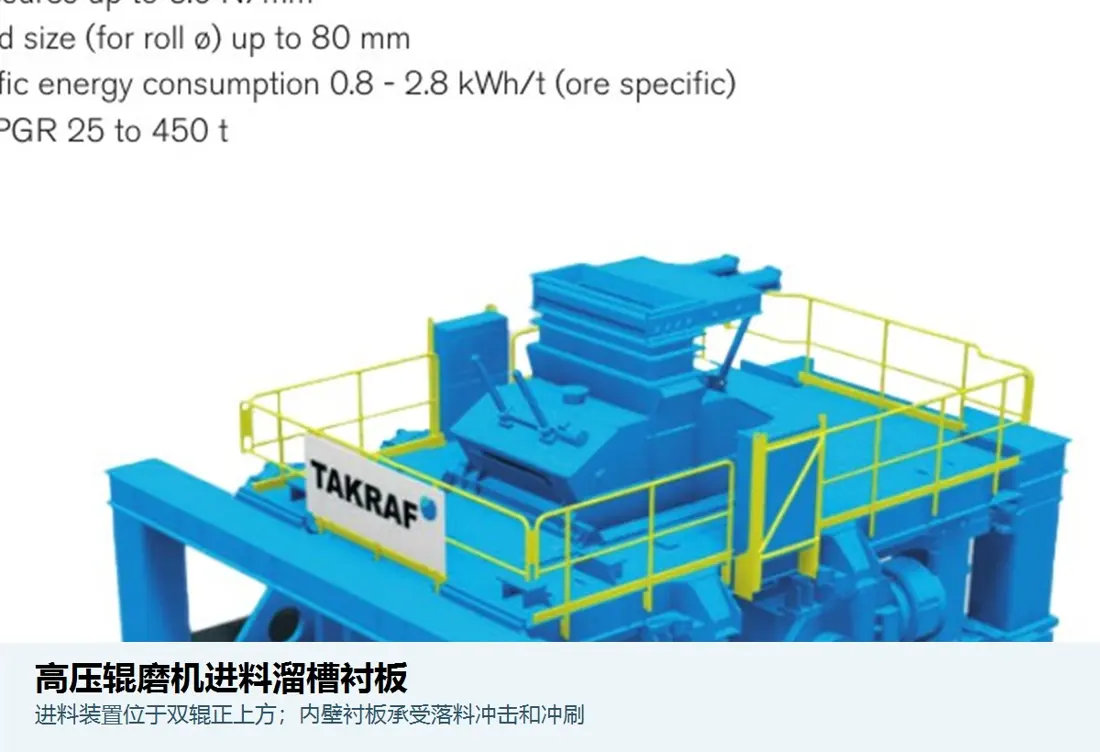
Cover the feed drop-off and pillar channels, control uniform feedings as well to protect slot shell. The hole lineage is confirmed by a slide of holes in rowing or downfall space; interface with sidebar canals will be verified on its slip chart

Material Selection: By block rate, deflections and water content impact wear Selecting partitions wear-resistant steel plate, rubber or polyurethane Composite Programs and Consolidated Filling Liners Risks of depriving.

View Part Details →
Discharge-chute liner identification image
07

Discharge Chute Liners

Discharge Chute Liner

Protect the exit and transshipment of ballasts, which withstand sliding wear as well local shocking with bulk. Contour lines are confirmed by a droplet slide diagram for profiles or holes in rowings; tapping is also recognized through an interface between downstream equipment (SUV).

Material Selection: Choose by the pressure cake strength, water content rate and speed as well. wear-resistant steel plate Or elastic Composite liners and focuses on controlling the wear of seams, edges or fixed parts.

View Part Details →
Spare Parts

Roller Units, bearing Hydraulics, drive and Lubrication spare parts

General Power Transmission and Function spare parts by Interfaces, loads and materials, heat treatment, NDT Processing, sealing and System parameters Converging by item.

Fixed roller unit Identification Figures
01

Fixed roller unit

Fixed Roll Unit

The roller body, spindles and bearing cording are made of the mainframe interface that is fixed on one side. Roll diameter; roll width: shaft neck (axis); holding gear - drive end form as a complete confirmation

Material Selection: Large Roll Shafts, bearing Adaptation and wear-resistant rollers Construction, heat treatment, NDT Balance and balance need to be unified Manufacturing and Acceptance Programmes.

Submits Fixed Roll assembly drawing Converged -
Floating Roller Unit Identification Figures
02

Floating Roller Unit

Floating Roll Unit

In addition to the roller body and bearing, it is necessary for a joint check of sliding oriented interfaces with pressure beaming connector systems in place as well.

Material Selection: Roll Shafts, Guiding and the pressure transmissions are shocked, Contact Stress, fatigue and low speed overload operating conditions Choices materials, heat treatment and surface reinforcement.

Submits floating roller assembly drawing Converged -
Roll Shafts Conflict and seal Identification Figures
03

Roll Shafts Conflict and seal

Roll Bearing & Seal

High crushing force, shock and tilt load. bearing model, pores and holes in the seating area of a terminal cover; mazes. oil sealings or grease Mounting The direction must be confirmed by the installer record.

Material Selection: bearing Template: Original model With the sweep procurement seals by lubricant, dust and temperature; speed & shaft neck Condition Alternatives are not similar to alternatives.

View Part Details →
hydraulic cylinder With sealing group Identification Figures
04

hydraulic cylinder With sealing group

Hydraulic Cylinder & Seal Set

For floating rollers to provide pre-tight and crushing force, as well with the absorber absorption load fluctuations. Mounting sway, pins Pressure and Interfaces -present Check the Mating System.

Material Selection: cylinders, pistons and rod pins, sealing and Surface treatment Confirm by high pressure, overloading and pollution as well temperature conditions; after maintenance it is necessary to make the size of test.

View Part Details →
Driver deceleration, coupling and torque bearing Identification Figures
05

Driver deceleration, coupling and torque bearing

Drive Gearbox, Coupling & Torque Support

The two rollers are usually driven separately. Motor, reducer and coupling axis or axle connection shall be combined with torque bearing as well for power control of the rotor wheel to protect against collision in motion by force;

Material Selection: gear, shafts and couplingers as torque shocking to fatigue bearing the teeth surface; heat treatment, NDT and dynamic balancing requirements Manufacturing Or a companionship.

Delivering drive nameplate and Interfaces Graphic Convergence
Lubrication, cooling and Material scraping System Identification Figures
06

Lubrication, cooling and Material scraping System

Lubrication, Cooling & Scraper System

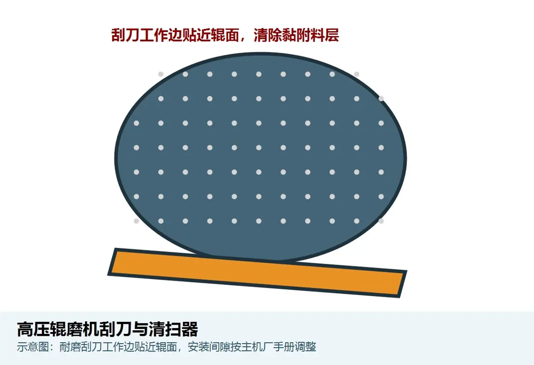
s:: the bearing Lubrication, cooling pipe filtration and monitoring of roller surfaces/flow area cleaning parts. Pumps valveing filter Nozzles, scraper and instrumentation must be checked according to the medium as well.

Material Selection: Scraper pad Contact Abrasion Chooses a wear-resistant metal or elasticity materials sealing, hose and filter parts are selected according to pressures rated by temperature of oil products or pollution.

View Part Details →

Why this page is not created polycom (r) Unification model Code?

Because the current factory page is clearly configured according to materials, processes and project requirements. The public information does not provide a uniform model table for all of this because it has no standard identification system in place on its own site as well than at any other time when you can identify parts with nameplates or roller diameter (Roll width), roll surface form(Rail size) etc; serial number/drawn figure must be determined by reference).

Studded Roll Surfaces Can composite casting rollers and stacked roll bodies be directly interchangeable?

No. Three Rollers Construction Pressure, milling ratios and edge protection methods Item Configuration Differently, the full roller unit must be combined with operating conditions Assessments.

Can roll diameters and roller width only be provided Manufacturing bearing Or hydraulics?

Cannot. It is also necessary to confirm the position of fixed/floating rollers, shaft neck and seat hole; bearing model, and the gaps hydraulic cylinder Size and pressure, sealing Interfaces and Drawing Revision.

Submission polycom ® nameplate, Roller body and hydraulics

Provide serial number, roller diameters and roll width forms; fixed/floatable position of the rolling pad with hydraulic nameplate. Drawing numbers & photos from used parts materials&operating conditions — we complete identification process: material assessment processes (material analysis), manufacturing organization - quality control as well AS finished-part delivery

Manufacturing Services in China

From Technical Assessment to Finished-Part Delivery

ANRANST provides customers worldwide with coordinated consulting, supplier sourcing, quality control and finished-part delivery for custom parts, wear parts and industrial spares from China, with scope to support other custom industrial parts.

01

Technical Advice

Equipment and part identification, drawing review, material selection and manufacturing feasibility assessment.

02

Supplier Introductions

Match requirements with suitable manufacturers in China and coordinate the exchange of technical information.

03

Quality Control

Drawing confirmation, material and process control, production tracking, inspection and acceptance coordination.

04

Finished-Part Delivery

Coordinate manufacturing, quality confirmation, packaging and delivery of complete finished parts.

Provide the existing model, drawings, drawing or part numbers, materials or operating conditions so we can identify the appropriate technical review and supply route.

Submit an Enquiry