thyssenkrupp Polysius TITAN double-shaft hammer crushers

Part of the current Polysius cement raw-material crushing range. Identify wear parts, spares and maintenance tools by model, feed opening, rotor dimensions, hammer arrangement and grate basket.

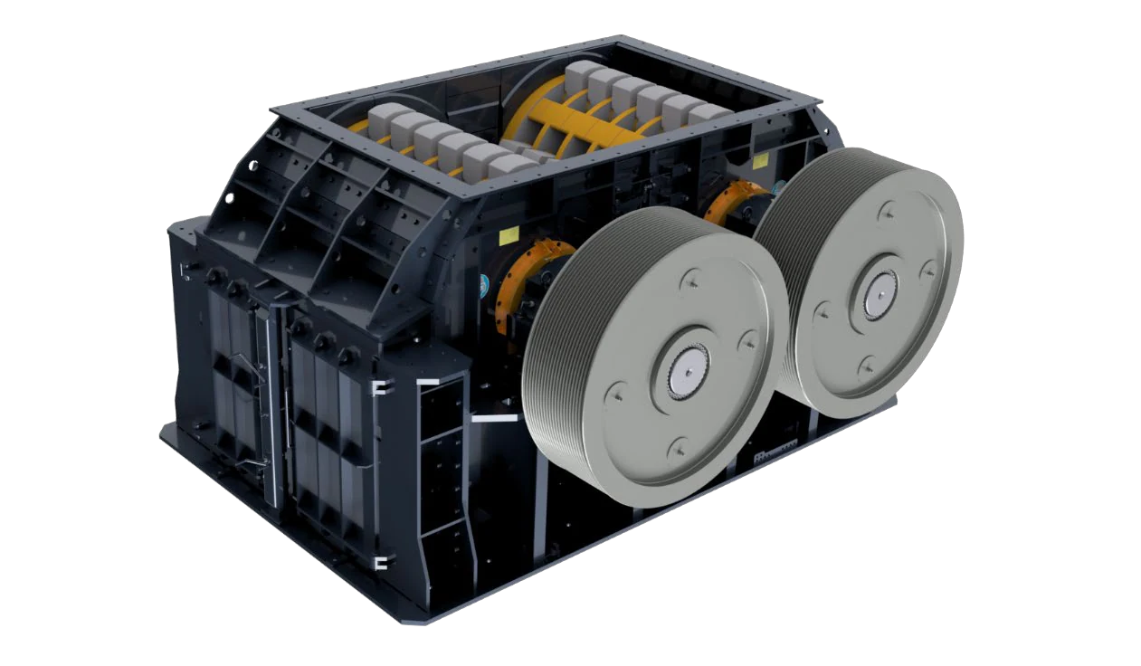
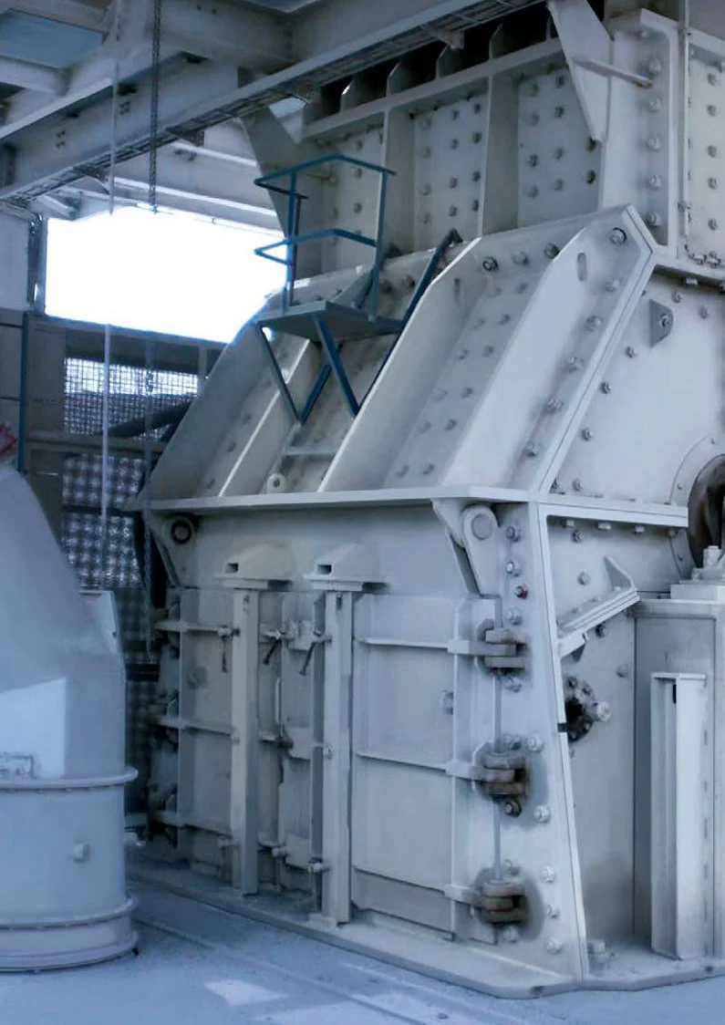
OEM TITAN unit image showing twin rotors, side doors, drives and grate-basket maintenance areas.
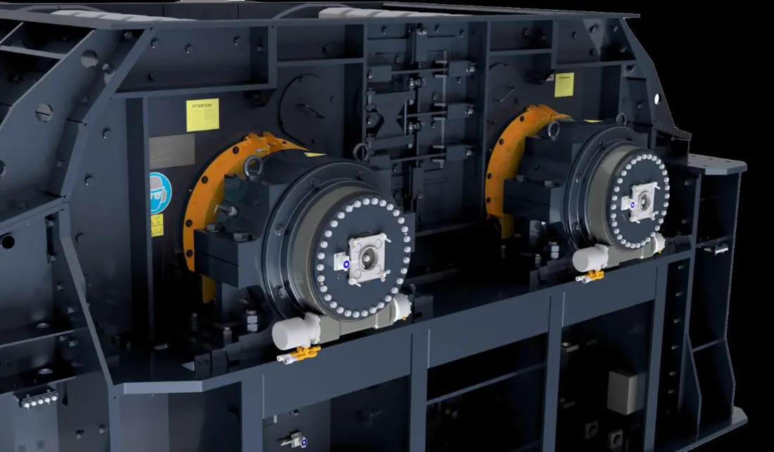
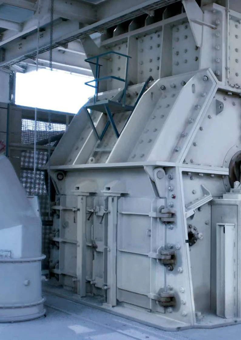
OEM installation image for identifying the feed opening, housing, rotor shaft ends and maintenance access.
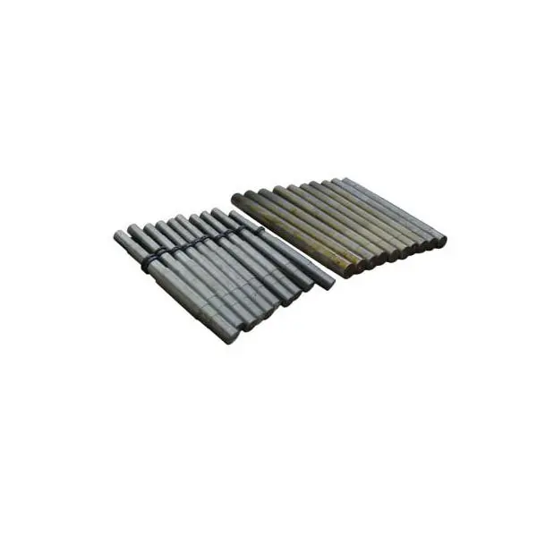
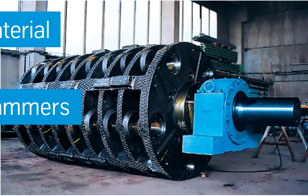
OEM five-hammer-axle rotor. Check hammer rows, discs, axles and end supports as an assembly.
OEM Equipment Reference

Models, rotors, hammers, grate baskets and tools in one place

TITAN pre-crushes material between two rotors, crushes it further against the anvil and controls product size through discharge grates. It handles medium-hard raw materials such as wet limestone, marl, clay, chalk and gypsum. This page focuses on data and technical routes needed for spare-parts supply.

19Standard models in the OEM brochure
1320–2400 mmPublished rotor diameter range
180–3150 t/hReference capacity at 30–90 mm grate gaps
2Twin-rotor crushing arrangement
Standard Models and Key Dimensions

TITAN models, feed openings and rotor dimensions

The complete table follows the thyssenkrupp TITAN OEM brochure. Capacity varies with material, product size and configuration; use it for preliminary installation and parts identification.

Standard modelFeed opening dimensionsRotor diameter × widthReference capacity at 30–90 mm grate gaps
TITAN 40 D 502350 × 1290 mm1320 × 1340 mm180–280 t/h
TITAN 48 D 502350 × 1510 mm1320 × 1560 mm220–320 t/h
TITAN 56 D 502350 × 1730 mm1320 × 1780 mm260–370 t/h
TITAN 48 D 752700 × 1280 mm1600 × 1340 mm300–430 t/h
TITAN 56 D 752700 × 1480 mm1600 × 1540 mm350–500 t/h
TITAN 64 D 752700 × 1680 mm1600 × 1740 mm425–650 t/h
TITAN 72 D 752700 × 1880 mm1600 × 1940 mm500–750 t/h
TITAN 72 D 1002850 × 1970 mm1800 × 2030 mm600–900 t/h
TITAN 80 D 1002850 × 2180 mm1800 × 2240 mm700–1100 t/h
TITAN 88 D 1002850 × 2390 mm1800 × 2450 mm800–1200 t/h
TITAN 60 D 1603100 × 1850 mm2000 × 1920 mm900–1350 t/h
TITAN 70 D 1603100 × 2150 mm2000 × 2220 mm1050–1500 t/h
TITAN 80 D 1603100 × 2450 mm2000 × 2520 mm1250–1700 t/h
TITAN 90 D 1603100 × 2750 mm2000 × 2820 mm1500–2100 t/h
TITAN 100 D 1603330 × 3000 mm2000 × 3120 mm1750–2400 t/h
TITAN 96 D 1803900 × 2760 mm2400 × 2840 mm1750–2400 t/h
TITAN 108 D 1803900 × 3100 mm2400 × 3180 mm2000–2800 t/h
TITAN 70 D 2203700 × 2550 mm2200 × 2520 mm1950–2750 t/h
TITAN 80 D 2203700 × 2890 mm2200 × 2860 mm2250–3150 t/h
Before manufacture, confirm full model, serial number, hammer rows and weights, rotor width, grate gaps, basket design, drawing and revisions.
Thyssenkrupp Polysius

Component Location Diagram

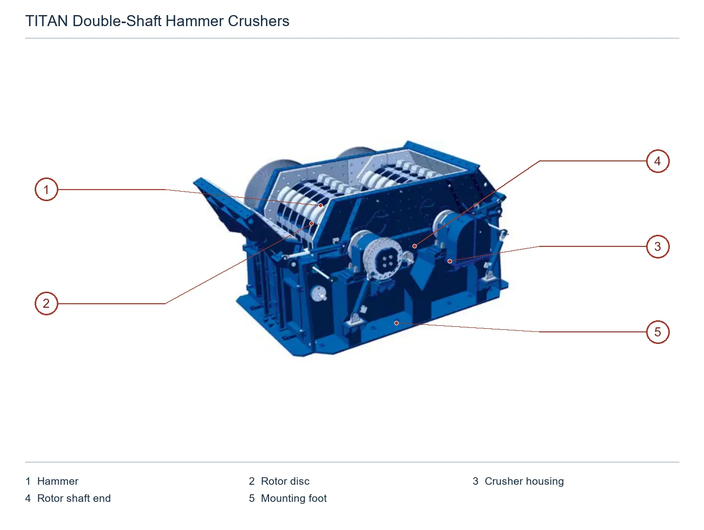
The numbers on the diagram correspond one to one with the rows below.

Thyssenkrupp Polysius TITAN double-shaft hammer crusher – Component Location Diagram
No.ComponentLocationApplies to
1HammerVisible swinging hammer on near rotor perimeterTITAN
2Rotor discParallel discs along near rotorTITAN
3Crusher housingBlue crusher housing outside rotorsTITAN
4Rotor shaft endExposed rotor shaft end projecting from front rightTITAN
5Mounting footLower mounting foot at front rightTITAN
Wear Parts

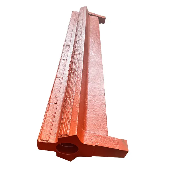
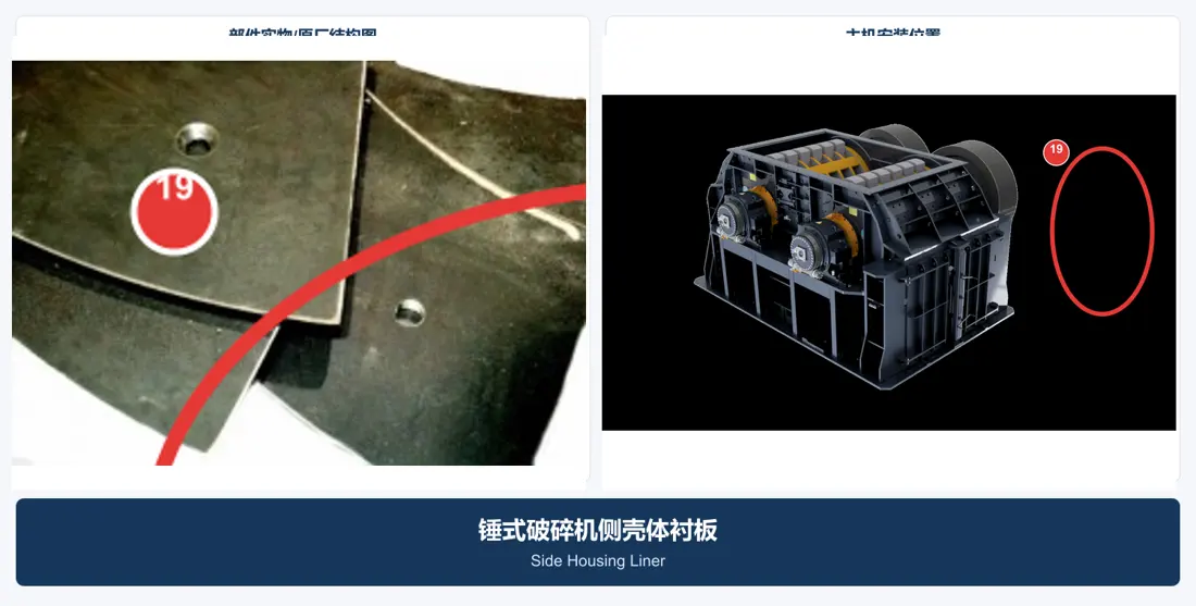
Hammers, anvils, grates and housing wear parts

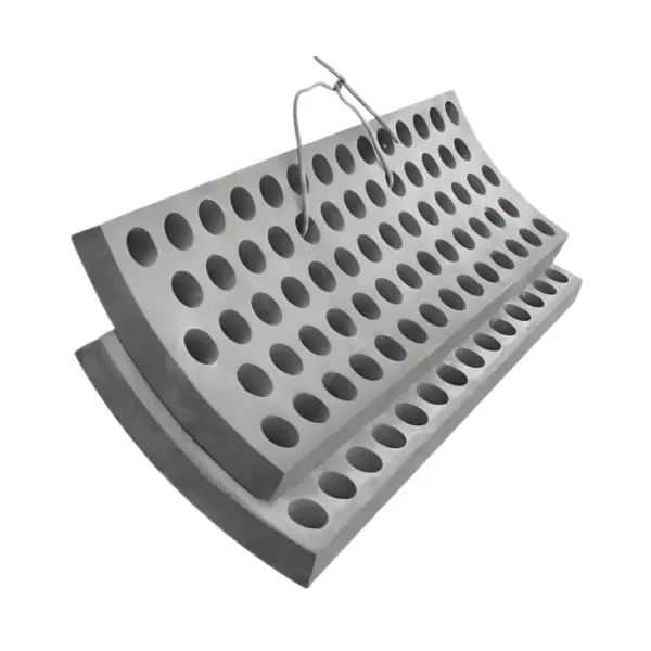
Impact, compression and sliding wear differ by position. Hammers, anvils, bars, grate segments and housing liners link to their respective component and material pages.

Spare Parts

Rotors, hammer axles, supports and drive spares

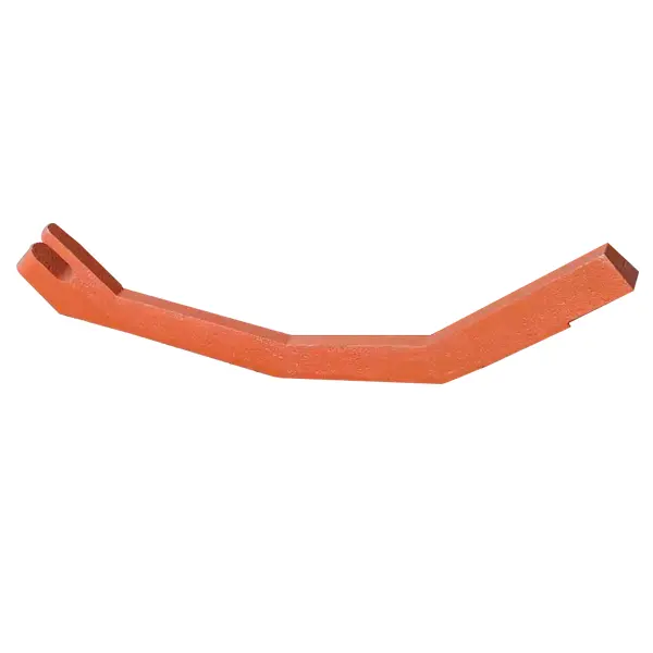
Confirm rotor assemblies, pentagonal shafts, hammer axles, bearing housings, pulleys and grate-basket trolley parts for their respective interfaces, loads, manufacturing and inspection requirements.

Pentagonal rotor shaft
02

Pentagonal rotor shaft

Pentagonal Rotor Shaft

The OEM brochure shows a pentagonal shaft matched to revised discs and hammer weights. Its section, journals, keys or connections, disc positions and heat treatment cannot be replaced by a generic round-shaft design.

View the common part page →
Grate-basket trolley rollers and guides
06

Grate-basket trolley rollers and guides

Grate Basket Trolley Roller & Guide

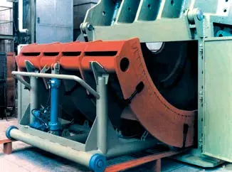
These support hydraulic basket removal and installation. Confirm wheel diameter, track gauge, flanges, bearings, guides and clearance to side doors against the site arrangement.

View the common part page →
FAQ

Frequently asked questions

Is TITAN 80 D 160 enough to identify a hammer?

No. Confirm serial number, hammer weight and rows, bore, axle, rotor discs, rotation direction, drawing and revision.

Should hammers, grates and anvils use the same material?

Do not assume so. Impact, compression, sliding wear, fixing and fracture risks differ. Select materials and processes separately for each position and duty.

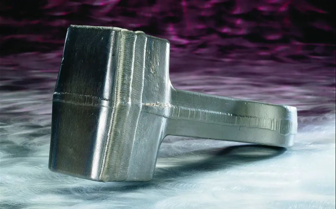
Is the internal label Hammer Head@15kg an OEM model details?

No. It is a descriptive filename without a traceable OEM catalogue reference to a TITAN model, position and drawing revision, so it is not published as an OEM model details.

Submit the full TITAN model, hammer arrangement, grate basket and drawings

Provide model, serial number, hammer weight, rotor and basket dimensions, grate gaps, drawing, worn-part photos, materials and duty. We coordinate identification, material assessment, manufacturing, quality control and delivery.

Equipment Brand and ModelDrawingDrawing or DimensionsCurrent MaterialPhotographs of Failed PartsTarget Service LifeOperating Conditions
Request a Quote

Or contact us directly: +86 156 3797 3199
zzx@anranst.com

Manufacturing Services in China

From Technical Assessment to Finished-Part Delivery

ANRANST provides customers worldwide with engineering assessment, production at certified foundries to the customer technical requirements, quality control and finished-part delivery for custom wear parts and industrial spares, with scope to support other custom industrial parts.

01

Drawing and Engineering Review

We review mating surfaces and interface dimensions and assess material, heat treatment and manufacturing feasibility.

02

Material and Heat-Treatment Specification

Material grades and heat-treatment processes are specified order by order, stated in the technical agreement and tracked through production.

03

Quality Control

Drawing confirmation, material and process control, production tracking, inspection and acceptance coordination.

04

Finished-Part Delivery

We coordinate manufacturing, quality confirmation, packaging and delivery of complete finished parts in a workable, closed-loop supply process.

Provide the equipment brand, complete model and serial number, part name, part number or drawing number, drawing revision, quantity, material requirements and duty. If identifiers are unavailable, send photographs and key dimensions.

Submit an Enquiry