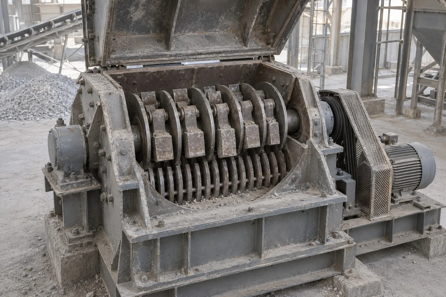
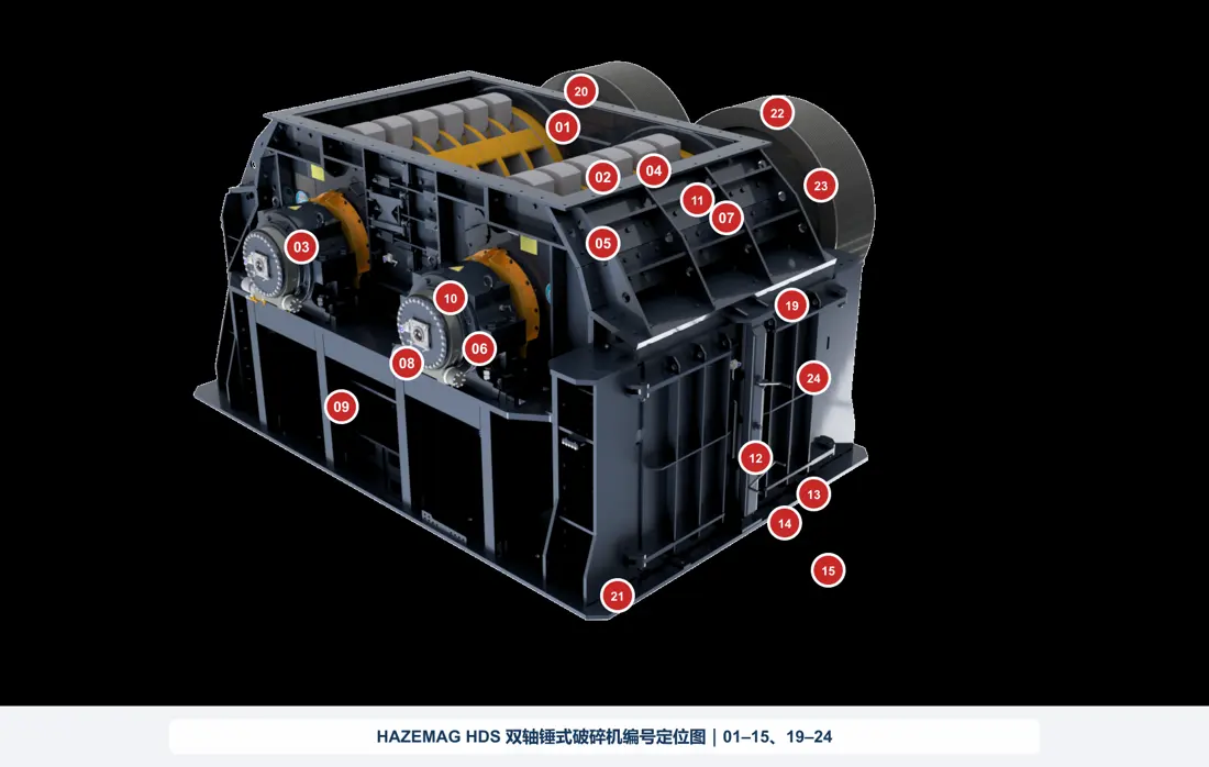
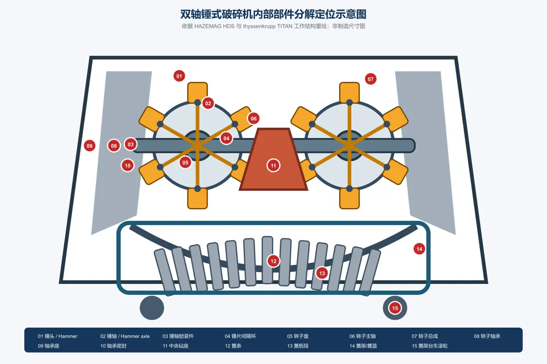
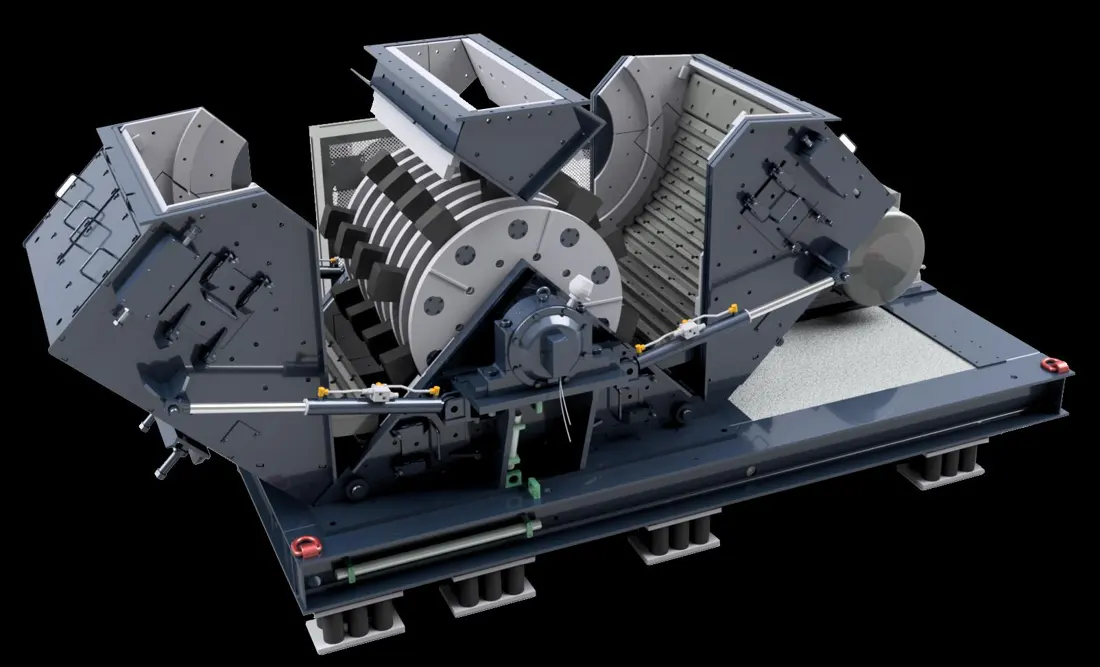
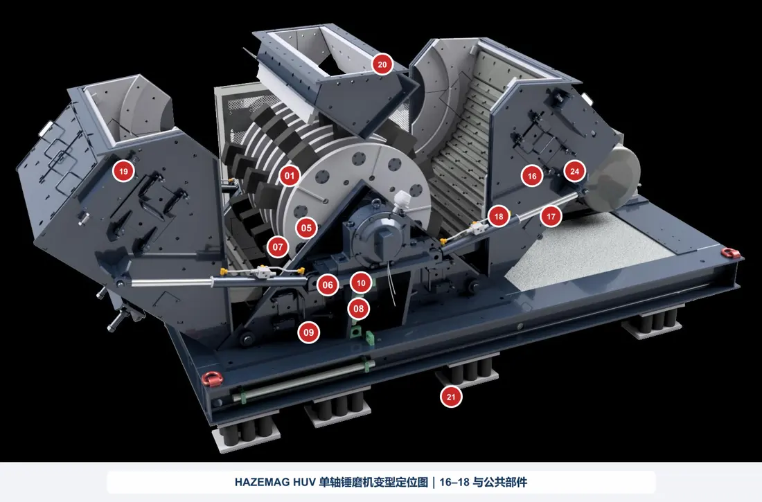
Double-shaft hammer crushers are mainly used for primary crushing of soft to medium-hard, moist or sticky cement raw materials. Two counter-rotating rotors break down large feed before further impact and shearing at the central anvil. Discharge grate openings control the product top size.
Equipment Parts
Part Identification and Technical Details
Explore part names, images, material options and technical requirements. Select a card to open the corresponding replacement part page.
Individual parts
Individual and Maintenance Parts
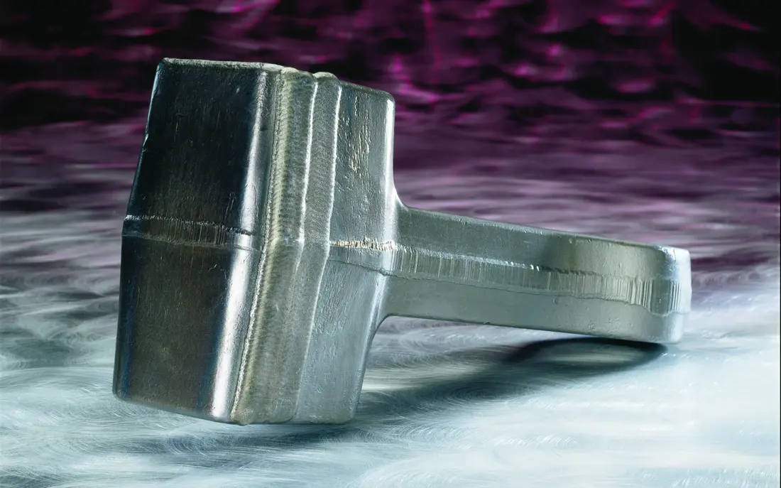
01
Hammer / Swing Hammer
- Equipment Configuration
- Shared by Twin-Shaft and Single-Shaft Designs
- Installation and Function
- Swing freely on hammer pins around the rotor perimeter
- Material Options
- Forged alloy steel / manganese steel / high-chromium iron or bimetallic composite
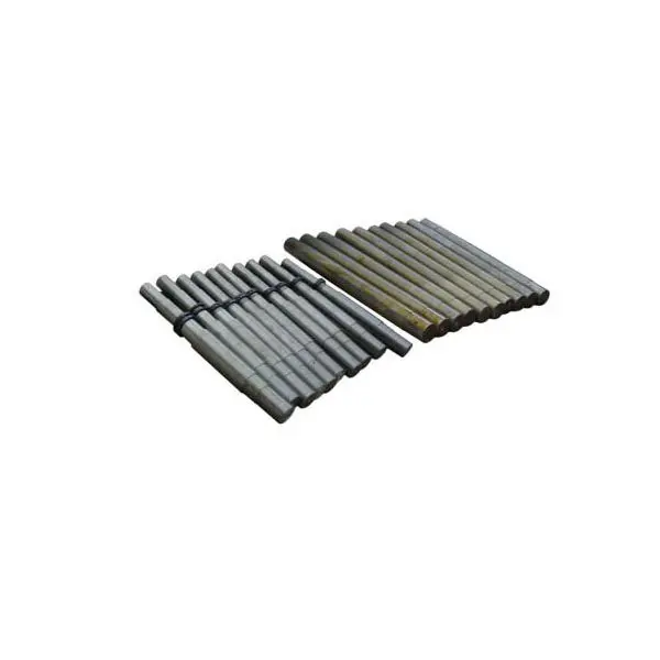
02
Hammer Axle / Hammer Pin
- Equipment Configuration
- Shared by Twin-Shaft and Single-Shaft Designs
- Installation and Function
- Passes through the rotor discs and supports the hammers
- Material Options
- Quenched and tempered 42CrMo / 4140 / 34CrNiMo6 steel
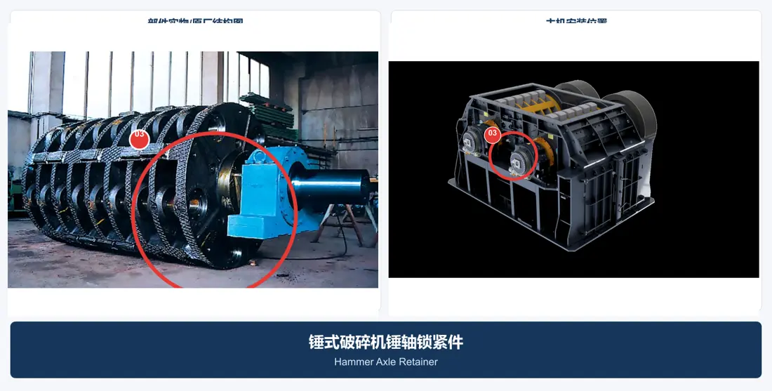
03
Hammer Axle Retainer
- Equipment Configuration
- Shared by Twin-Shaft and Single-Shaft Designs
- Installation and Function
- At the hammer pin ends and outer rotor discs
- Material Options
- 42CrMo / 4140 or OEM-specified high-strength locking hardware
04
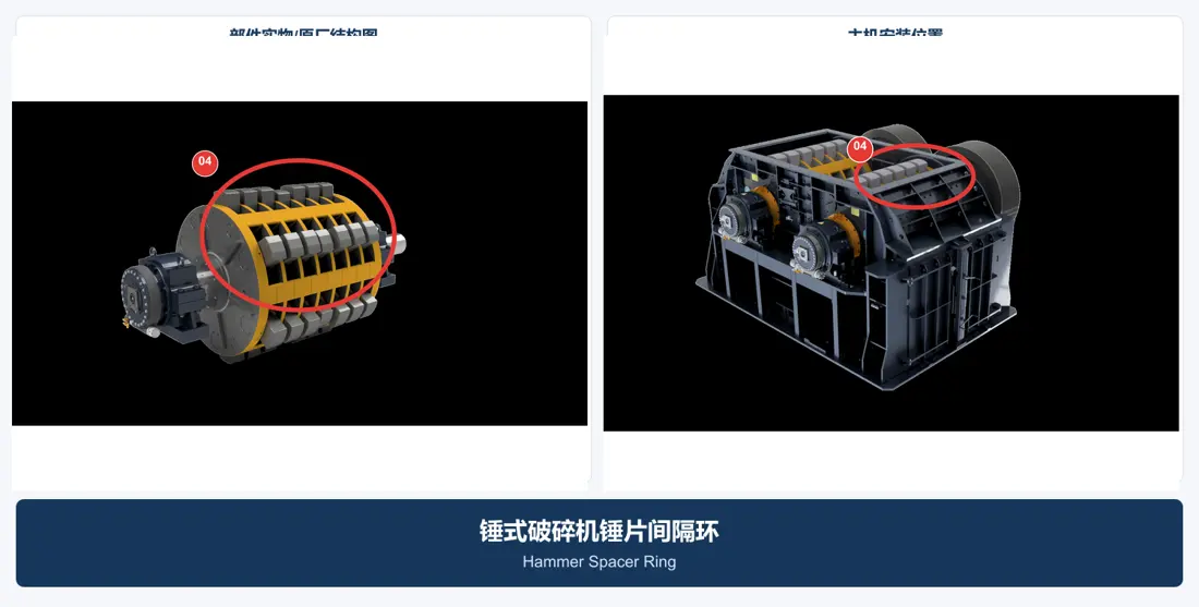
Hammer Spacer Ring
- Equipment Configuration
- Depends on rotor design
- Installation and Function
- Between a hammer and rotor disc, or between adjacent hammers
- Material Options
- Quenched and tempered alloy steel / abrasion-resistant steel
05
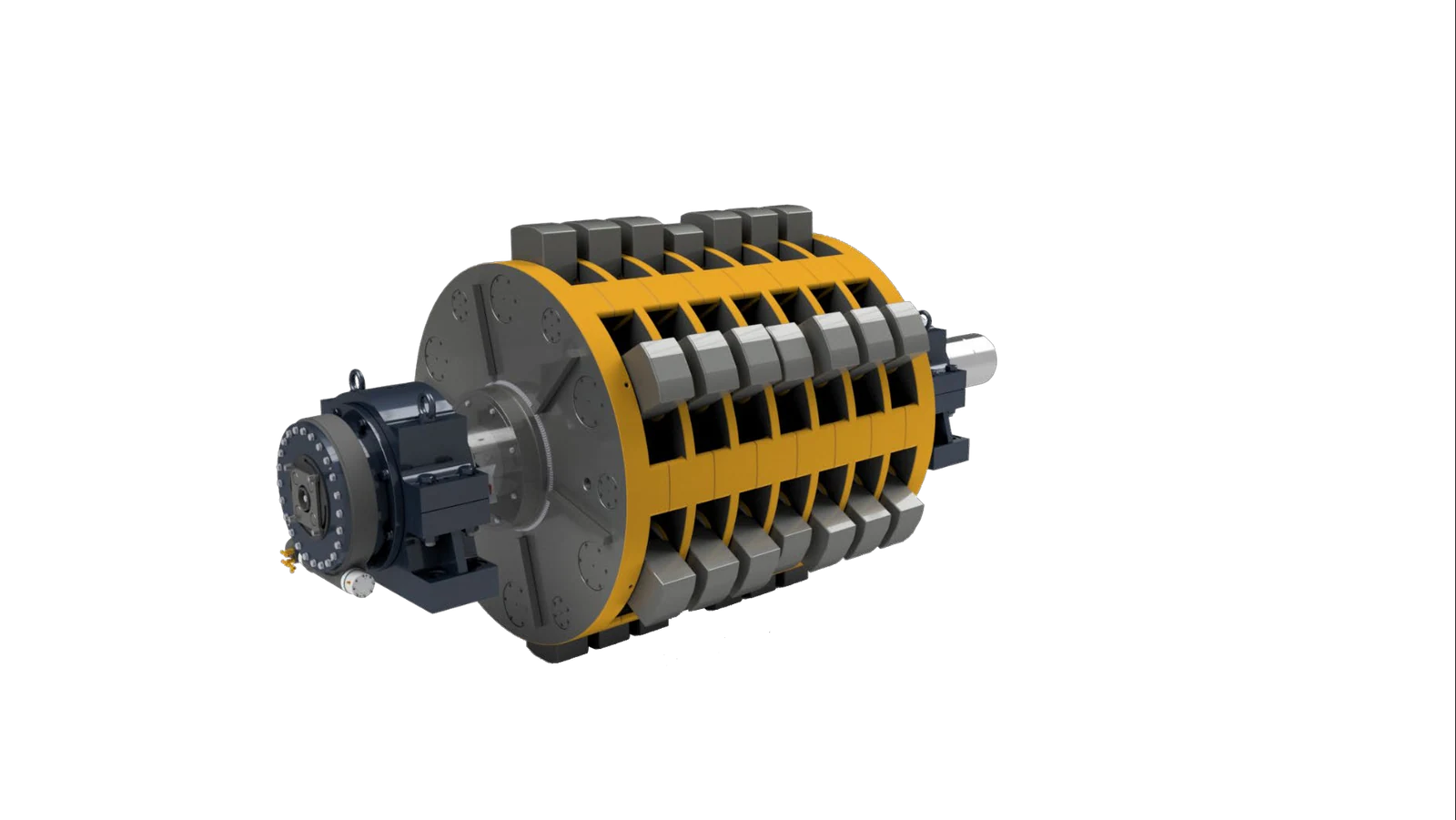
Rotor Disc
- Equipment Configuration
- Double-shaft / disc-type single-shaft
- Installation and Function
- On the main shaft between the hammers
- Material Options
- High-strength cast steel / quenched and tempered alloy steel / welded structural steel
06
Rotor Shaft
- Equipment Configuration
- Shared by Twin-Shaft and Single-Shaft Designs
- Installation and Function
- Passes through the rotor and bearings at both ends
- Material Options
- Forged, quenched and tempered 42CrMo / 4140 / 34CrNiMo6 steel
07
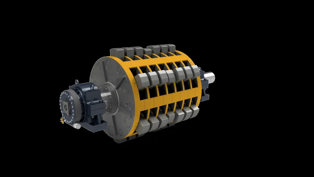
Rotor Assembly
- Equipment Configuration
- Shared by Twin-Shaft and Single-Shaft Designs
- Installation and Function
- Rotating assembly at the center of the crushing chamber
- Material Options
- Complete assembly of main shaft, rotor discs, hammer pins and hammers
08
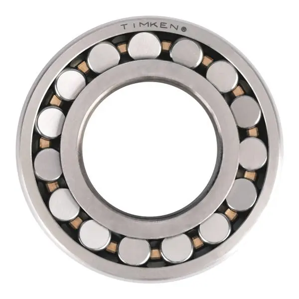
Rotor Bearing
- Equipment Configuration
- Shared by Twin-Shaft and Single-Shaft Designs
- Installation and Function
- Inside the bearing housings at both ends of the main shaft
- Material Options
- 100Cr6 / SAE 52100 bearing steel
09
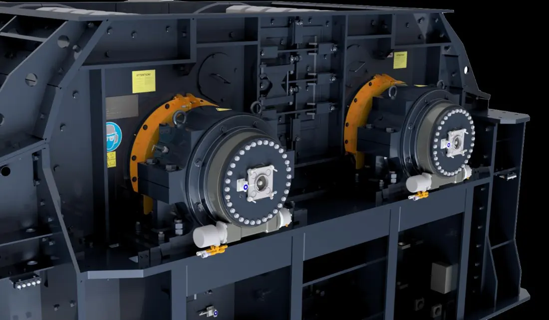
Bearing Housing
- Equipment Configuration
- Shared by Twin-Shaft and Single-Shaft Designs
- Installation and Function
- Outside the casing at both ends of the main shaft
- Material Options
- Cast iron / ductile iron / cast steel or OEM-specified construction
10
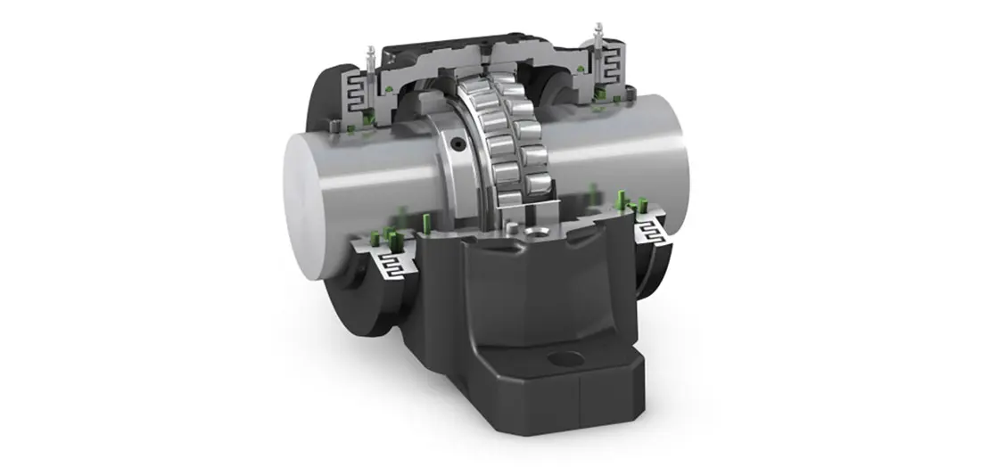
Bearing Seal
- Equipment Configuration
- Shared by Twin-Shaft and Single-Shaft Designs
- Installation and Function
- At the bearing housing and projecting main shaft
- Material Options
- Labyrinth/Taconite seals with NBR, HNBR, FKM or V-ring seals
11
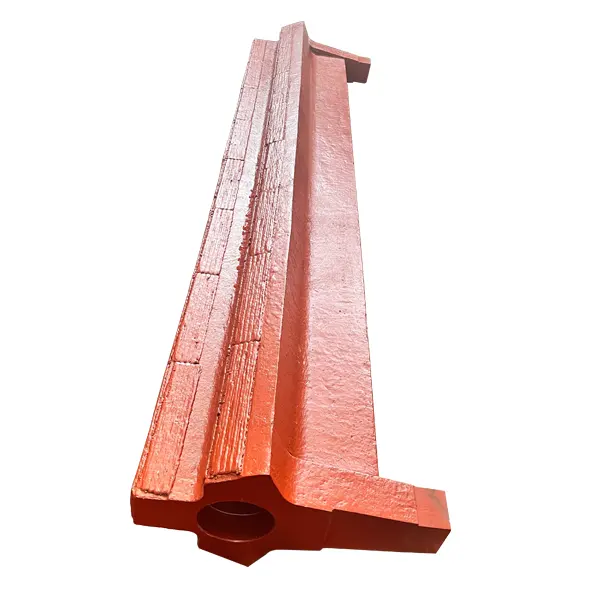
Central Anvil
- Equipment Configuration
- For HDS/TITAN double-shaft designs
- Installation and Function
- Between the two rotors
- Material Options
- Manganese steel / abrasion-resistant cast steel / surface-reinforced composite
12
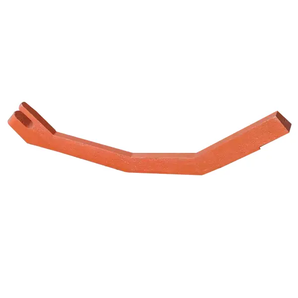
Grate Bar
- Equipment Configuration
- Designs fitted with discharge grates
- Installation and Function
- Discharge area beneath the rotors and anvil
- Material Options
- Manganese steel / abrasion-resistant alloy steel / hardfacing
13
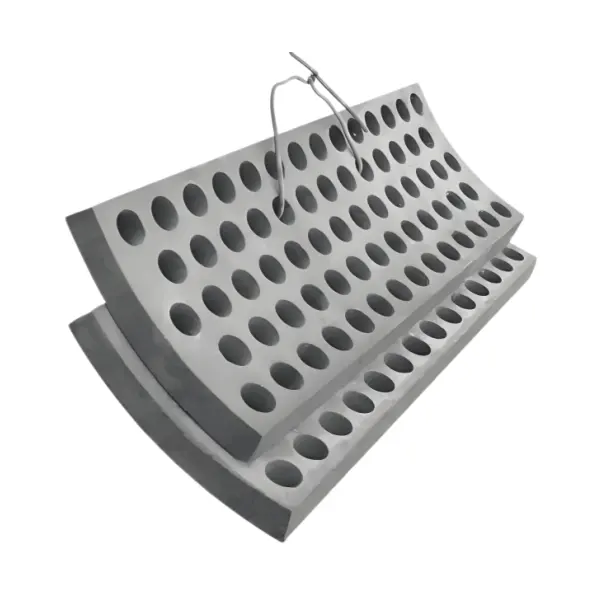
Grate Segment / Screen Plate
- Equipment Configuration
- Designs fitted with discharge grates
- Installation and Function
- Segmented screening surface on the curved grate frame
- Material Options
- Manganese steel / high-chromium white iron / abrasion-resistant or heat-resistant cast steel
14
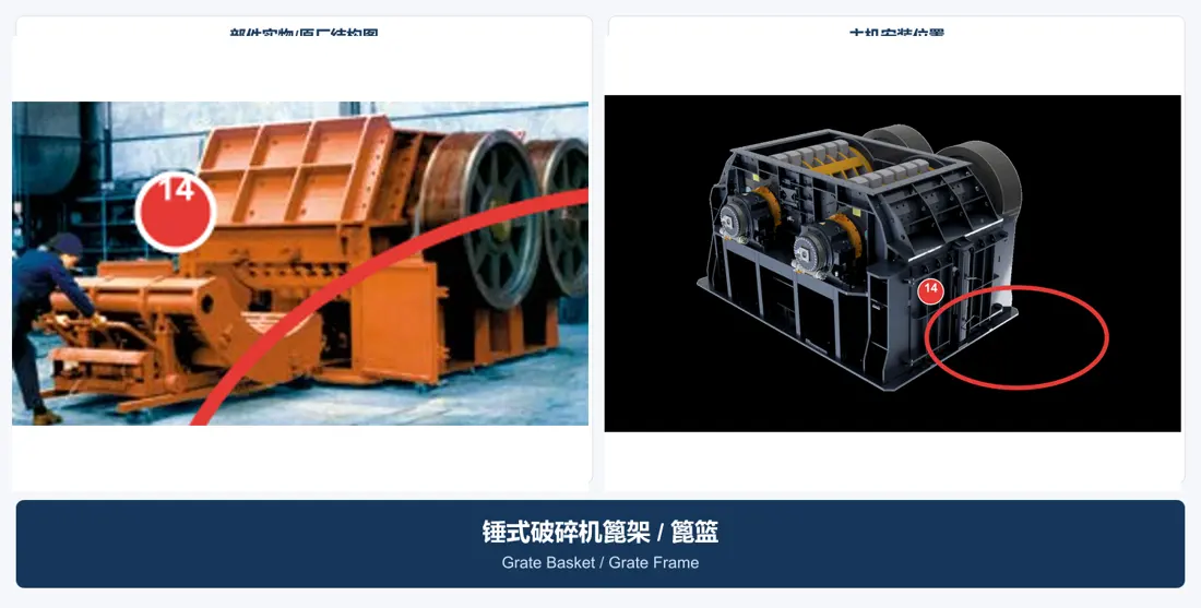
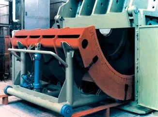
Grate Basket / Grate Frame
- Equipment Configuration
- HDS/TITAN, mammut and related designs
- Installation and Function
- Supporting frame around the grate bars and segments
- Material Options
- High-strength cast steel or welded structural steel
15
Grate Basket Trolley Roller and Guide
- Equipment Configuration
- Withdrawable grate frame designs
- Installation and Function
- Beneath the grate frame carriage and along casing guides
- Material Options
- Surface-hardened 42CrMo/C45 wheels, wear-resistant guide rails and rolling bearings
16
Impact Wall Liner / Breaker Plate Liner
- Equipment Configuration
- mammut/HUM and selected single-shaft variants
- Installation and Function
- Fixed breaker wall outside the rotor
- Material Options
- 1040/1045 carbon-manganese steel / manganese steel / martensitic or high-chromium materials
17
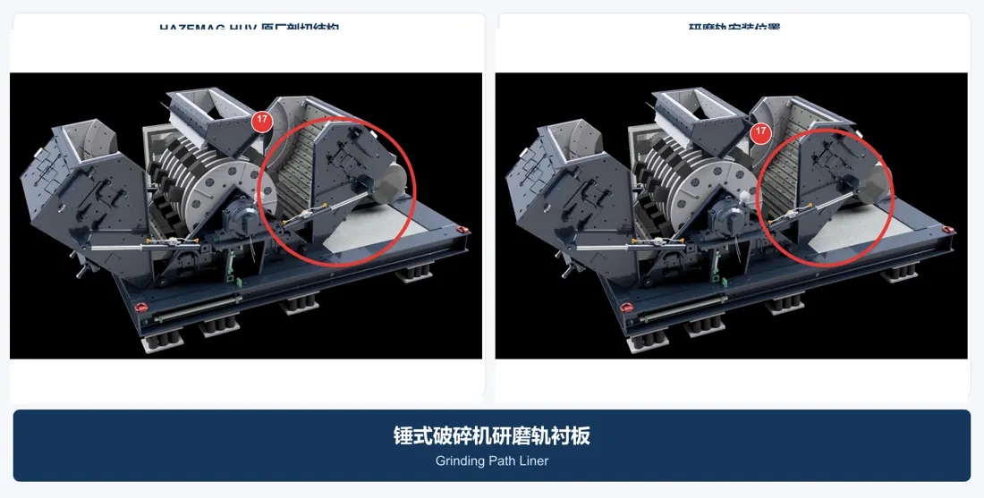
Grinding Path Liner
- Equipment Configuration
- For HUV/HNM variants
- Installation and Function
- Grinding path working surface outside the rotor
- Material Options
- Martensitic steel / high-chromium white iron / bimetallic composite
18
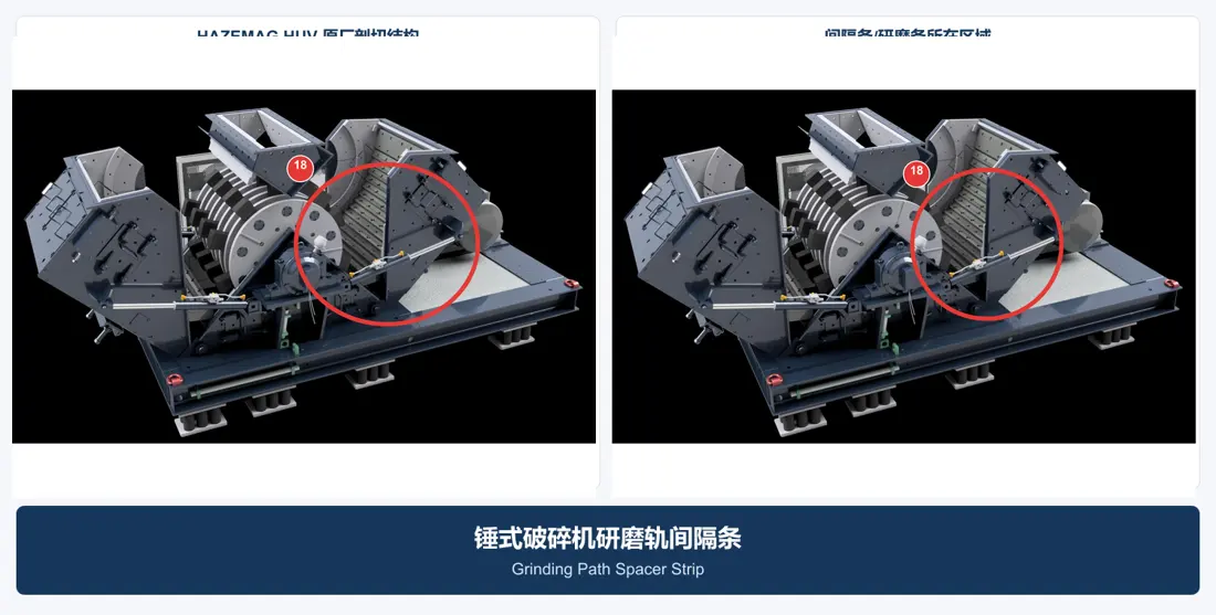
Grinding Path Spacer Strip
- Equipment Configuration
- For HUV/HNM variants
- Installation and Function
- Between grinding path liners or at their supporting surfaces
- Material Options
- Quenched and tempered alloy steel / abrasion-resistant steel / hardfacing
19
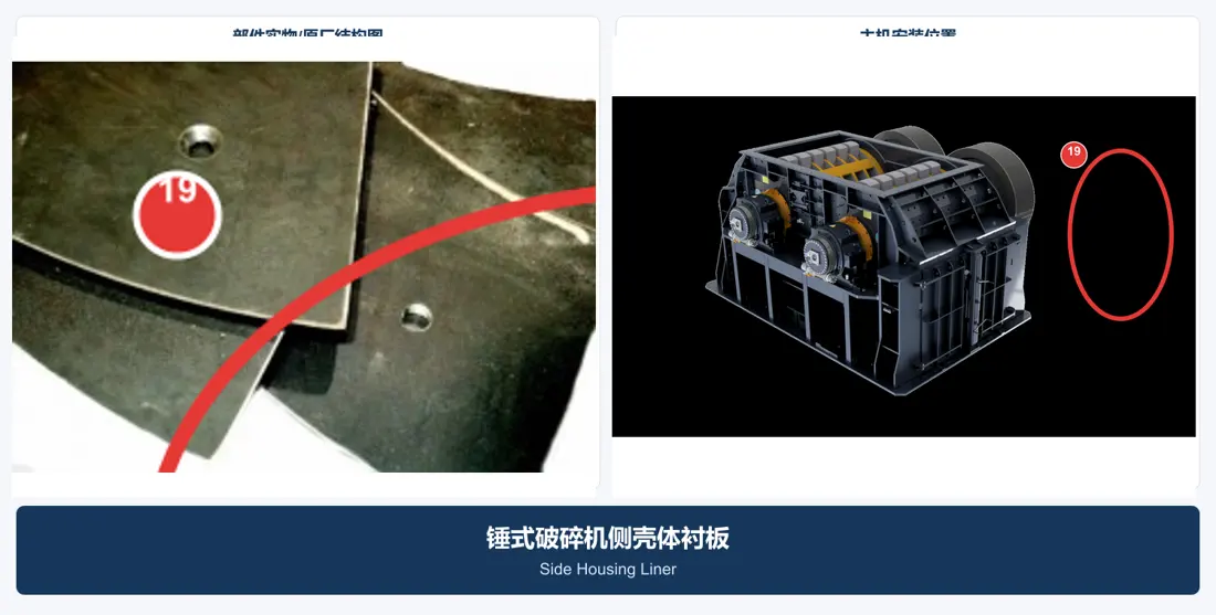
Side Housing Liner
- Equipment Configuration
- Shared by Twin-Shaft and Single-Shaft Designs
- Installation and Function
- Left and right sidewalls of the crushing chamber
- Material Options
- 1040/1045; carbon-manganese steel; manganese steel; wear plate. Confirm hardness, tensile strength and other numerical properties against a material specification, manufacturer data or approved project record before publishing.
20
Feed Inlet Liner
- Equipment Configuration
- Shared by Twin-Shaft and Single-Shaft Designs
- Installation and Function
- Upper feed opening and initial impact zone
- Material Options
- wear plate; manganese steel. Confirm hardness, tensile strength and other numerical properties against a material specification, manufacturer data or approved project record before publishing.
21
Discharge Chute Liner
- Equipment Configuration
- Shared by Twin-Shaft and Single-Shaft Designs
- Installation and Function
- Below the grates and in the discharge chute
- Material Options
- wear plate; hardfaced plate; ceramic; rubber. Confirm hardness, tensile strength and other numerical properties against a material specification, manufacturer data or approved project record before publishing.
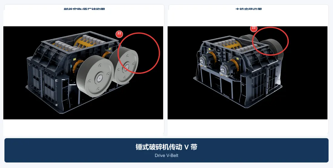
22
Drive V-Belt
- Equipment Configuration
- Belt-Driven Models
- Installation and Function
- Between the motor pulley and crusher pulley
- Material Options
- EPDM/chloroprene rubber body with polyester or aramid tensile cords
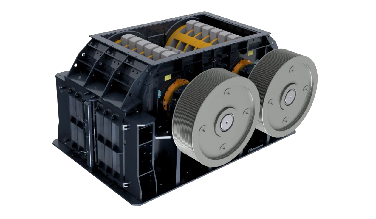
23
Drive Pulley
- Equipment Configuration
- Belt-Driven Models
- Installation and Function
- At the outer end of the rotor main shaft
- Material Options
- Grey cast iron / ductile iron / cast steel or fabricated steel wheel
Materials for similarly named parts may differ by OEM, machine model and operating conditions. Confirm the machine model, drawing and measured dimensions before ordering or manufacture.
7. Procurement and Acceptance Checks
1. Identify whether the equipment is an HDS/TITAN double-shaft crusher, mammut/HUM single-shaft unit, or HUV/HNM hammer mill; the generic name alone is insufficient for ordering. 2. Provide the OEM, model, serial number, rotor diameter and width, hammer arrangement, number of hammer pins, model details and latest assembly drawing. 3. Weigh hammers, pins, spacers and locking parts as sets and assemble to the OEM balance diagram. 4. Inspect main shafts, hammer pins and rotor discs for material, heat treatment, hardness, UT/MT results, critical dimensions and fatigue-sensitive areas. 5. Confirm grate material, curvature, clearances, segment identification, orientation and thermal expansion. 6. After grate frame and carriage maintenance, check guide parallelism, wheel load distribution, locking and operating position. 7. Record bearing clearance, fits, heating temperature, grease quantity, seal condition and baseline vibration during replacement. 8. Do not increase liner bolt strength or hardness without checking grip length, toughness and fatigue requirements.
Materials for similarly named parts may differ by OEM, machine model and operating conditions. Confirm the machine model, drawing and measured dimensions before ordering or manufacture.