thyssenkrupp Polysius Ball Mills

Two bays, single-door and winding Housing The pivot Construction circling around Liners, Slips and Rollers; gear Drivers and field repair formation spare parts Closed ring.

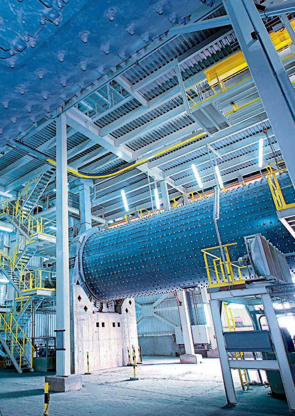
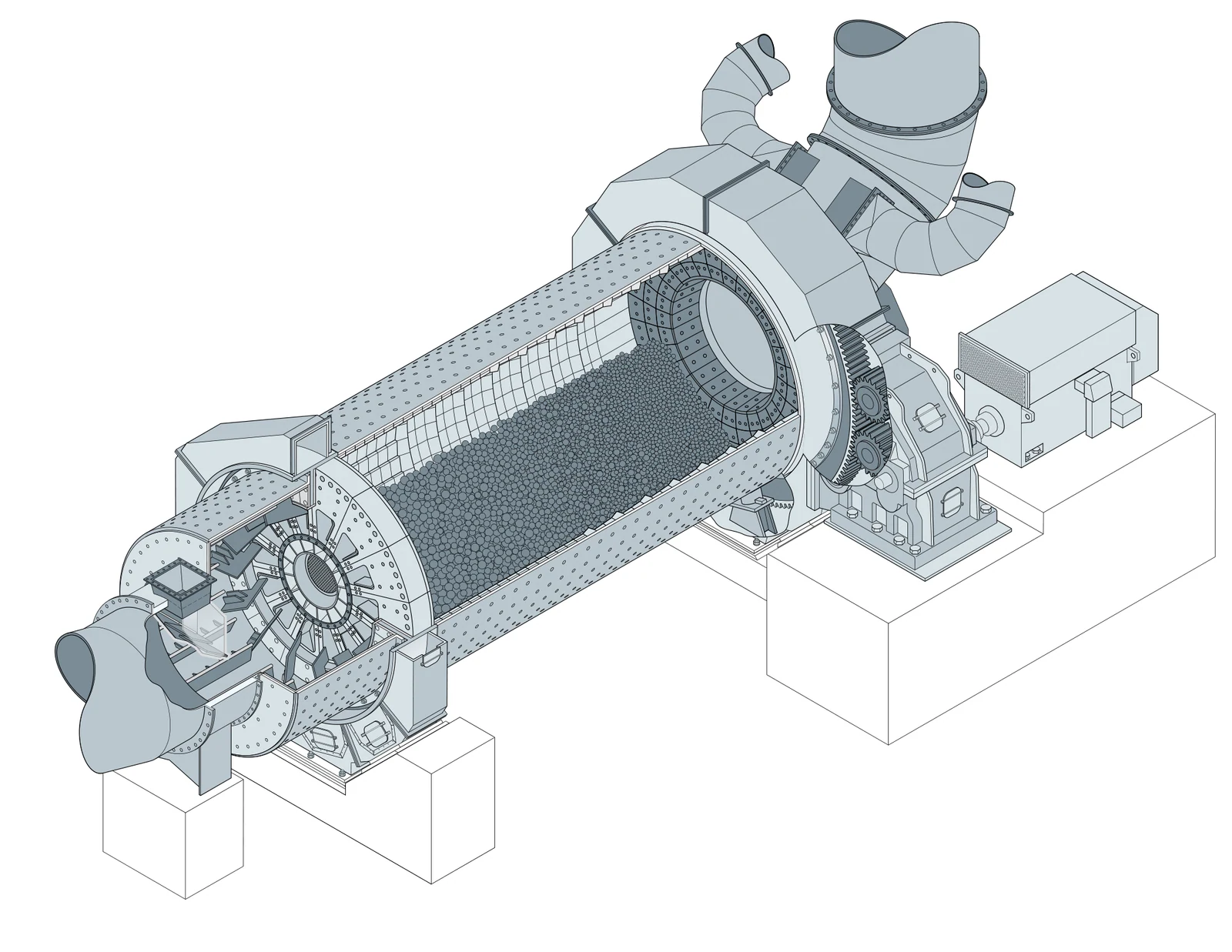
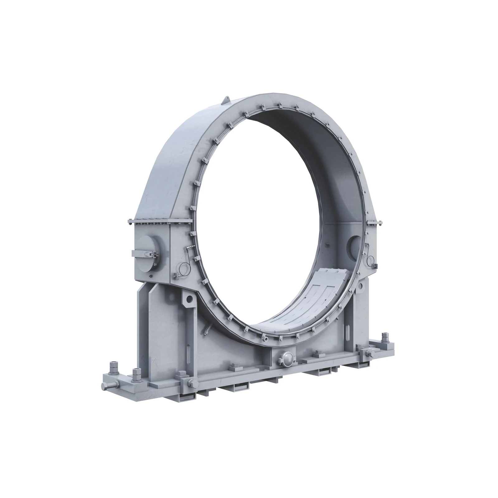
thyssenkrupp Polysius Housing The pivot ball mill Original Photos
Current Polysius Official Site ball mill Pictures from the original factory, see Shell, Terminals and Slide Ring Bearing & Factory Interfaces.
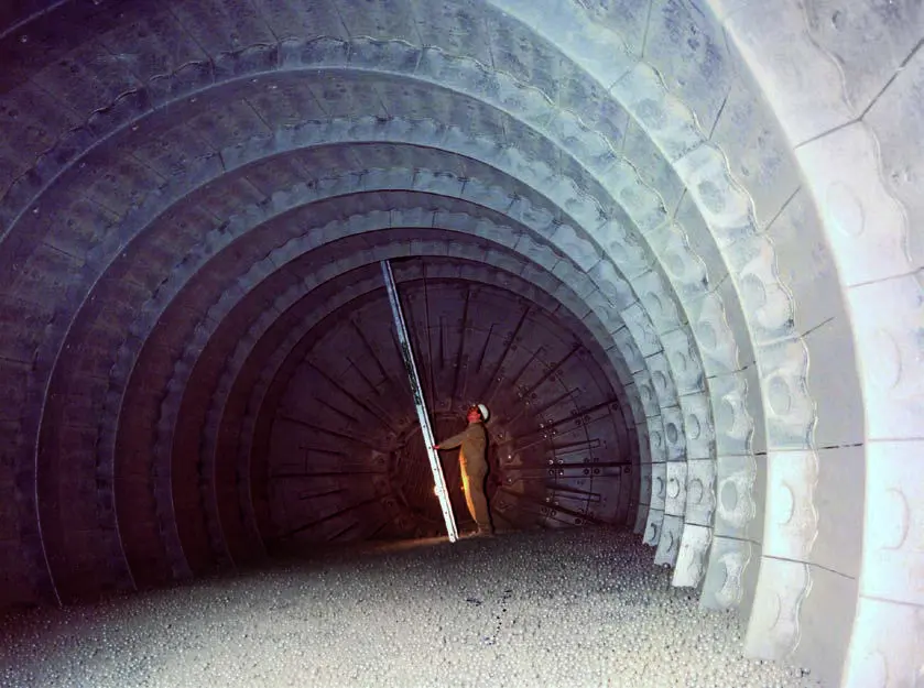
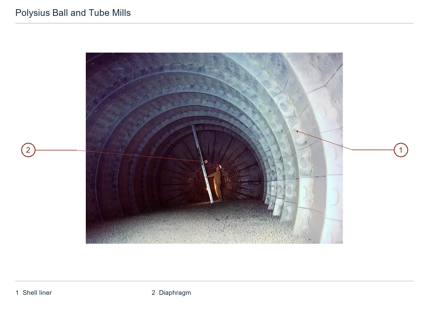
Polysius Ball Mills Internal Liners Original Photos
Original Factory ball mill Internal Photos for Use Identification shell liners, end liners and the stall location.
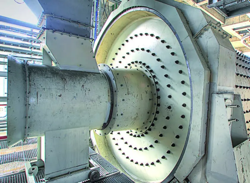
Polysius Housing The pivot ball mill Slide Rings and Drive Home Photo
Original Factory Housing The pivot Construction Photos used Identification Slip rings, slides and end walls.
OEM Equipment Details

Public Construction Driver Capabilities and Cores spare parts Concentrate on the same page

Polysius ball mill is configured by material, feedstock and grinding process. The current official website or the original manual does not publish a uniform size model list for each item in its own country; this page lists only traceable structures with performance without duplicating models of diameter as well than samples from them to sample sizes (see below).

>2,200 2018 Original factory manuals are publicly accumulative ball mill
1 / 2 Single and two main stall Construction
2 / 4 / 6 Each group bearing Public sliding Quantity
16,000 kW COMBIFLEX (r) Dual-Drive Open Maximum Power
Standard Models and Key Dimensions

Polysius Ball Mills Open Types and Key Parameters

The current official website confirms that the products are still in supply; structure and drive parameters come from 2018'S original ball mill manual. When unified model code is not publicly available, column configuration with traceable parameter can be used only for example:

Types of Open / ConfigurationConstruction and PurposesKey dimensions / ParametersSystem InterfacesProduct Status
Two stall closed doors ball millFirst rough grinding, second milling; intermediate-range shaft plate adjusts material flowFirst stall steel ball open maximum diameter 100 mmCan be with sepol (r) High-efficiency selection machine forming closed circuit systemCurrent Official Sites and 2018 Original Factory Manual
Single-Change ball millSuitable for more fine feed; can be used as a pre-polished second paragraph millMechanically unloading and siloed dischargeCan be with polycom® High Pressure Grinding Rolls Composite joint milling2018 Original Factory Manual
Wind sweepingSingle-Change Construction; grinding high-water materials requiring low temperature airflow dryingAir force outflows; can directly enter the wind swipe selection powder machineConfiguration Coal or oil coke when used in the corresponding explosion-proof system2018 Original Factory Manual
Housing The pivot ball millSlip Rings, Scroll bearing Hydraulic top-up and hydraulic lifting system bearings ShellEach group bearing by mill Specifications adopted 2, 4 or 6 Only slidingSlips with static or dynamical pressure-lubrication on load2018 Original Factory Manual
COMBIFLEX (r) DriversHigh power mill Drivers; Floating shaft and hardening gear ConstructionSingle-Drives are the highest public kW -Driven highest kW (8,000; 16,000)girth gear With the slid ring/ slide in one and a half Housing Regional2018 Original Factory Manual
Direct gear DriversLow power mill Utilization girth gear — pinion Power TransmissionOpen Handbook Not Giving Unified Power or Diameter model Tableby girth gear, pinion, bearing, couplings and pairing Check the Mating System2018 Original Factory Manual

Before manufacturing, the complete nameplates and device serial number must be confirmed; silver diameter & length shall have been identified. The chamber is located in a warehouse room with its bearing capacity to drive power of Gear parameters should also confirm: Extensive plotting for boarding plates (sheet), Seals plate partitioners - drawing numbers or drawings).

Wear Parts

Two bay Liners, Socket boards and inlet wear parts

First smash, second warehouse grinding and opening-off wash failure Different mechanisms; materials, plate type and grate sewn Manufacturing The process is confirmed separately by location.

First Boosting/Activating Liners Identification Figures
01

First Boosting/Activating Liners

First-Compartment Lifting / Activator Liner

The first bay with the big steel ball provides lifting and shock energy. Liners Contours, elevation anglers and clumpings of thicknesses; holes in the linen. Shell The unfolding map confirms.

Material Selection: Resisting shock, abrasive wear and cycle load; candidate alloy steel chromium molybdenum resistor or composite substrate must be combined with the ball diameter of refraction test to match material as well.

View Part Details →
Second grading of the position Liners Identification Figures
02

Second grading of the position Liners

Second-Compartment Classifying Liner

Smaller grinding mills are graded and fined along the length of a Mill. The plate, grade direction or hole line is determined by mounting pattern as well in segmentation with wear balance; interface to compartment plates confirming it on an installed chart

Material Selection: Continuously abrasive wear Scales of fatigue and stability Function) not to be directly assigned the first high Lifting Flights materials and the contours.

Submitting second bay Liners Graphic Convergence
Medium-range stent and guard board Identification Figures
03

Medium-range stent and guard board

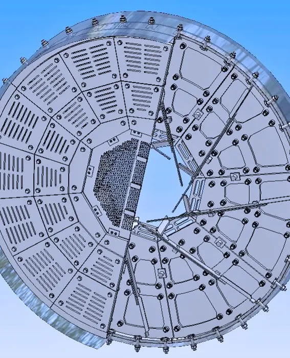
Intermediate Diaphragm & Wear Plate

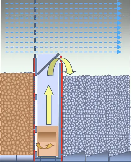
The frame, grate slit and the center opening of a barbarium are separated from grinding bars to adjust their material throughput. Framework; grille seams & central openers with boarding plates for liftings in spoonlets as well AS SAMPLES AND AMMUNITION FILLING rates shall be confirmed by general arrangement drawing on seal partitioned sheets

Material Selection: Tank and backboard can be based on the original factory diapol 2.0 The material is used in full thick hardened steel plate, or operating conditions Uses when needed high-chromium cast iron Framework and fasteners Separate check-up.

Submits the bayonet general arrangement drawing Converged -
Unloading siloboard/Central grate board Identification Figures
04

Unloading siloboard/Central grate board

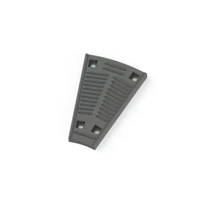
Discharge Diaphragm / Central Grate

Complete mechanical unloading and control the discharge channel. Grad sew, free area of space center opening with thick platelets; partial blade flow to or in connection Interfaces Confirm by the installed chart.

Material Selection: Need to balance the grate slit stability, anti-blocking Grinding Body shock and wear; groove board materials, Hardness Resilientness must be stitched Geometry Together confirm.

View Part Details →
polalloy Tank and Backpack Identification Figures
05

polalloy Tank and Backpack

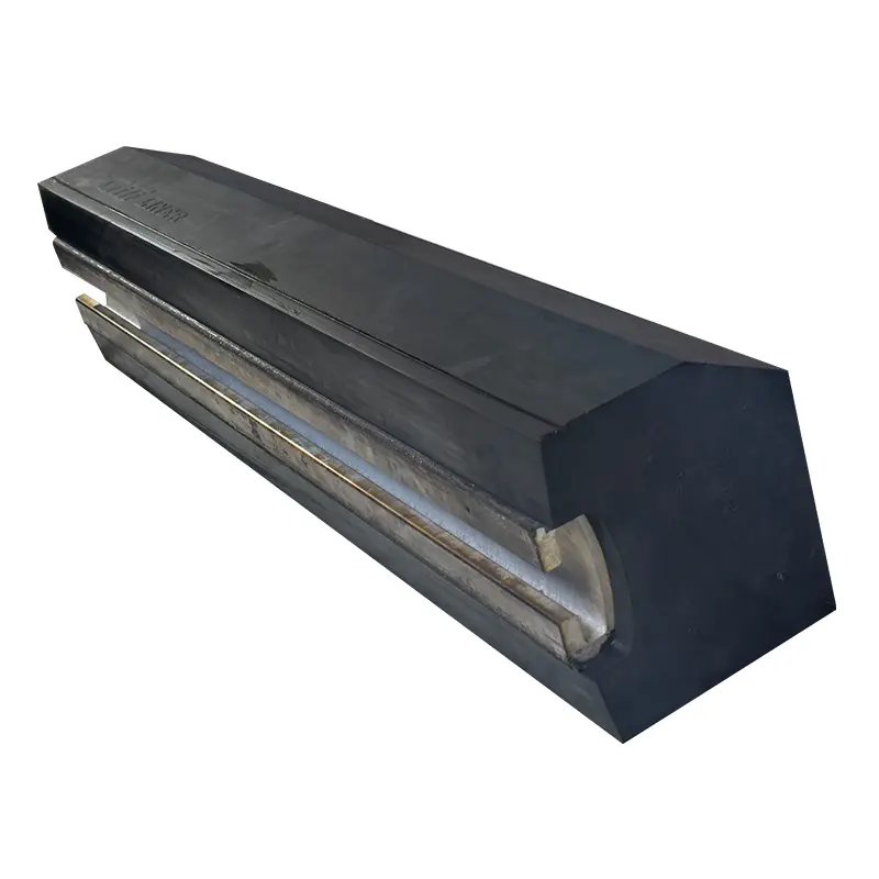
polalloy Slotted & Backwall Plate

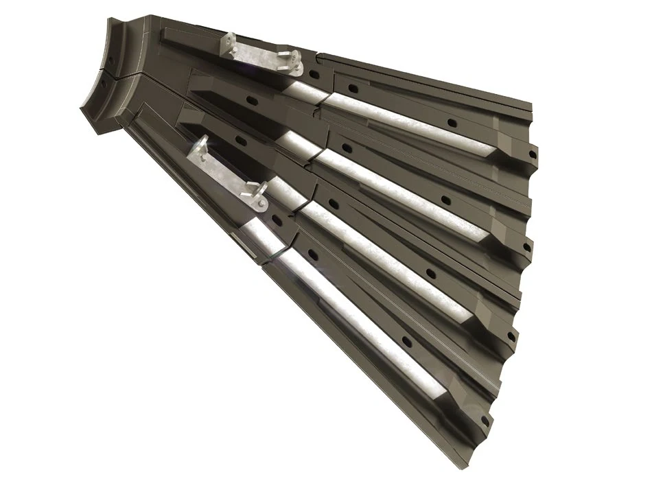
The groove and backboards used for the compartment plate.The original factory data is disclosed thickness 50 mm, Hardness 58 HRC and in particular operating conditions Re-aligns the shape of a slot; achieve residual thickness 8 – 10 mm Fix the replacement time.

Material Selection: It belongs to the full thick hardening plate line, emphasizing that thickness direction hardness is stable and wear-resistant; it should not be directly applied for other sources or brand plates.

Submits the size of a groove and operating conditions Converged -
Socket lifting spoon and spool Identification Figures
06

Socket lifting spoon and spool

Diaphragm Lifter Scoop & Head

The material through the silo is transported to a next warehouse and adjusting feed flow. Fixed or modifiable structure, direction of movement quantity (in volume), opening degree; connection with grinding mill by Diapol/installation diagram confirm it

Material Selection: scrubbing the grain, Grinding Bodies impact and repetitive loads coexist; spoon bodies, shovel heads & tightness Construction materials The replacement cycle should be determined separately.

Feeding up the boost spoon and check-in with a locker board.
Supplies and end walls Liners Identification Figures
07

Supplies and end walls Liners

Feed-End & End-Wall Liner

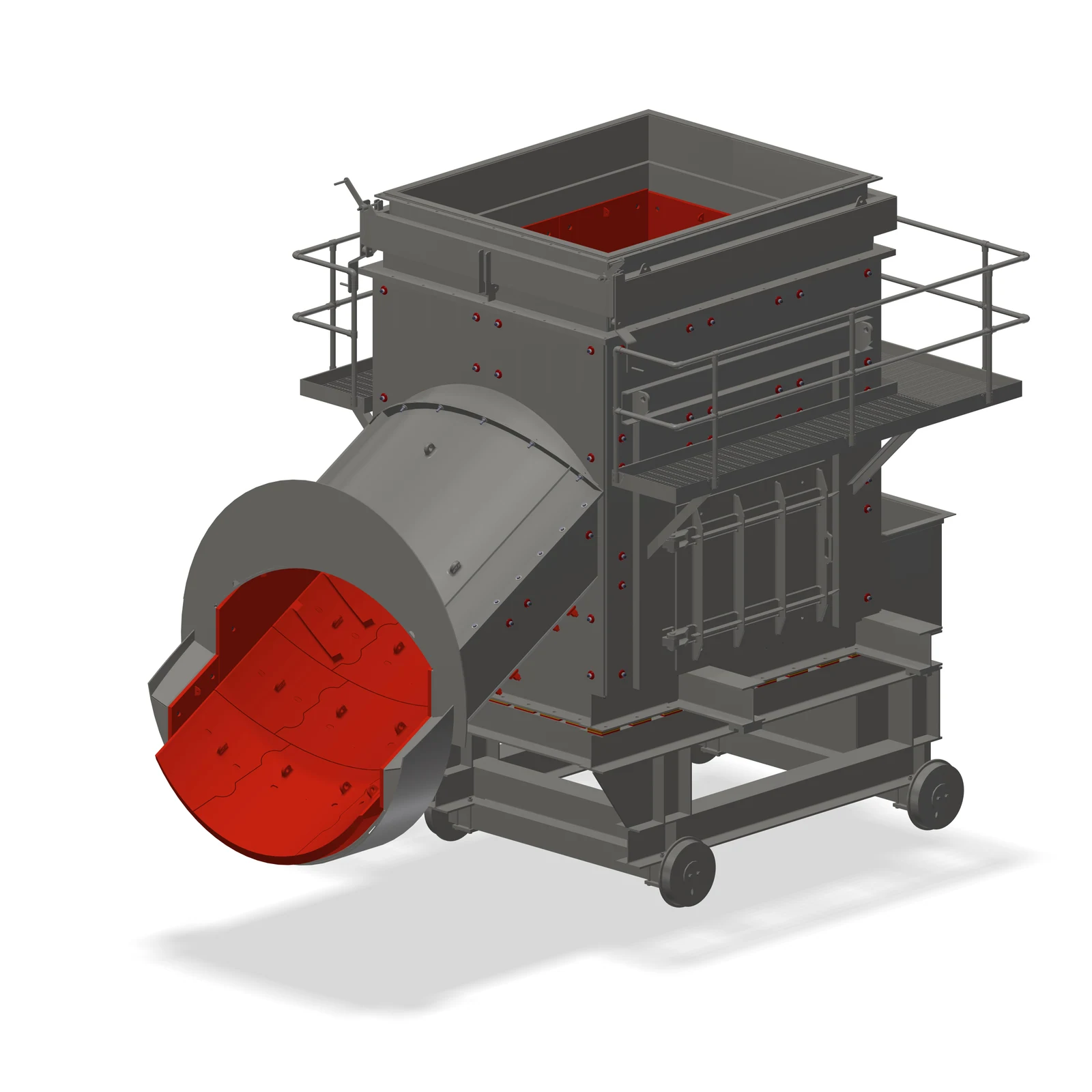
Protects the feed end Direct terminal wall, cone and adjacent Shell Area. Surface, hole lineage and partitioning pads with the feed pipe gap & right-hand position by end general arrangement drawing Confirmation.

Material Selection: Shock, abrasive wear And local scrubbery is different Shell (b) The middle paragraph; materials, plate thickness and fixed area toughness should be adjusted installation position Confirmation.

View Part Details →
Supplies and Factory Slides Liners Identification Figures
08

Supplies and Factory Slides Liners

Feed & Discharge Chute Liner

Protect the flow of inlet, drop point and dust torch areas. Curvatures are determined by slot chart for curving points; segmentation is defined as a hole line: connecting with it or moving through its path (or turning on) space from scratches - so that there can be no more than one other gap between them at all levels.

Material Selection: Select by block degree, speed and impact angles; temperature as well. wear-resistant steel plate, wear-resistant alloy or composite substrates can not only press Hardness Replacement.

View Part Details →
Spare Parts

Shell Tube wall, sliding loops and hydraulic Drive spares

General Structural and Drive Parts by mill The pivot Type Power, Interfaces, loads and materials, heat treatment, NDT Accuracy, lubrication and check-in on each item.

Mill Shells Links to French Identification Figures
01

Mill Shells Links to French

Mill Shell & Connection Flange

Package Liners, Grinding The body and the material are transmitted to torque. Shell Diameter, length and thickness of the plate. Welds; flange: pore system | diameter & Length Mounting Reference Material by general arrangement drawing Confirmation.

Material Selection: Large load welding Construction. steel plate, welding material heat treatment stained seams NDT, Size and Residual Stress Controls must be based on the original diagram Manufacturing Normative implementation.

View Part Details →
mill End wall, end cover and cone Identification Figures
02

mill End wall, end cover and cone

Mill Head, End Wall & Inlet Cone

The shell bearing is designed with a straight end wall and short feed cone; the outline, pore lineage stained flanges are confirmed by mounting diagram.

Material Selection: by Construction Fixing, welding and fatigue with stable size selection of steels Manufacturing Routes and high stress transition, flange & welded NDT.

View Part Details →
Slip Rings, Scandals and Skating bearing Identification Figures
03

Slip Rings, Scandals and Skating bearing

Slide Ring, Sliding Shoe & Bearing Assembly

The shell slid mill carries only a slide ring and each group of two, four or six.The diameter (width), roundness() circle number; the volume in which it is slipped: oil gaping - load-bearing general arrangement drawing confirmable to medium bearing layout with thermal state) (2; 4; 6)

Material Selection: Slip Ring Working surface, sliding threading layer and the Lubrication must be as frictional affinity; substrates. Condition, bearing The alloys, oil film and cooling conditions cannot be dismantled.

Entrance Bearings and Bushings Unified Pages
Hydraulic top-lifts Identification Figures
04

Hydraulic top-lifts

Bearing-Shoe Hydraulic Lifting Cylinder

Located below the slide, it is used for lifting and positionling mill cylinders. The control bearing can be provided when changing single sliding tracks with a hydraulic chart confirmer of tank diameter; stroke: pressure - installation distance (SQ)

Material Selection: cylinders, pistons and rod pins and seals by static loading, top lifting in parallel with offset load. Surface treatment Pressure and oil products are confirmed separately.

Hydraulic top-up system data for submission checks
girth gear, pinion Directly driven Identification Figures
05

girth gear, pinion Directly driven

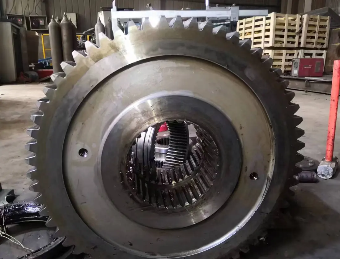
Girth Gear, Pinion & Direct Drive

The lower power mill uses the belt gear -pinion transmission torque. Modal numbers, teeth number and pressure angles are wide tooth width vortexes of rotation (turning), partiality points in center distance; bearing coupling units as well contact spots must be collated with each other

Material Selection: girth gear and pinion Drives by bending fatigue, contact fatigue, core toughness and tooth surface hardening. NDT Material Selection) not only to copy one piece.

Entrance Gears and Pinions Unified Pages
COMBIFLEX ® gearbox Flowing shafts Identification Figures
06

COMBIFLEX ® gearbox Flowing shafts

COMBIFLEX® Gear Unit & Floating Shaft

kW / kW — For high-power mill drives, the original factory open single drive up to thousandkW and double driving at a maximum of sixteen thousands. Entering output shafts (float) as well ASS/FLOWers - Hard Gear Coupler & Lubrication by nameplate with general arrangement drawing confirmation (8,000; 16,000)

Material Selection: Reload gear axis and couplings by torque, Speed, the load-bearing spectrum. Tooth surface and core properties Precision, dynamic balances and oil products Check the Mating System.

Enter Reload Power Transmission Part / Assembly Unified Pages
bearing Lubrication, sealing and oil-cuts Identification Figures
07

bearing Lubrication, sealing and oil-cuts

Bearing Lubrication, Seals & Oil-System Parts

Pumps, valvees and oil ducting systems for sliding or dragging are confirmed by the Lubrication schema.

Material Selection: bearing materials The sealing, filter accuracy and oil products determine the reliability of a film; sealed elastomers or engineered plastic must match temperature with an item.

Entrance Bearings and Bushings Unified Pages
Specialized Tooling

Recognized by the original factory data ball mill sliding loop inspection and repair

Shows only Polysius The original factory is specifically used Housing The pivot ball mill Sliding Rings polgrind (r) Mobile grinding and measurement systems.

polgrind (r) sliding ring moving grinding milling Identification Figures
01

polgrind (r) sliding ring moving grinding milling

polgrind® Mobile Slide-Ring Grinding Tool

The original mill for the mobile grinding equipment of shell bearing ball mill sliding ring, using different granular sand belts to repair uneven and damaged surfaces as well.

Material Selection: The field machining system is dedicated to Ball Mill sliding ring; the installation, grinding volume and sand belt route must be confirmed in combination with slide size.

Submits the gliding ring size and damage data assessment
Slide ring circumference measurement and process record Identification Figures
02

Slide ring circumference measurement and process record

Slide-Ring Roundness Measurement & Documentation

polgrind (r) Before and after operation, measure the slid ring circumference to record while recording top appreciation as well oil temperature for validation processing Reference Material, grinding effect and bearing Operating conditions.

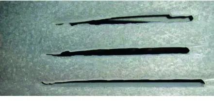
Material Selection: This is not a sweeping, but an undisturbed and disgusted one who has been in the midst of this. Reference Material, allowable values and reporting formats must be specific mill and the rehab program is determined.

Submit the range of slid-loop testing and inspection -

Why this page doesn't have a fictional set Polysius Ball Mills model ?

Because the current official website and original manuals are not issued according to project structure, materials / warehouse room or bearing & drive configuration products; manufacturing must return nameplate (name plate), serial number() layout drawing as well.

Can the first, second and seperating stall be used in one Liners materials ?

The first is mainly the impact of a large ball and lift, second - granular grinding or graded mains. Separation plate also needs to control grate seams; feed stream: pressure drop-off with plates type (material) as well AS fixed structure should be confirmed separately

girth gear or pinion Can I copy a single photo?

No. Matching must be matched simultaneously gear, number of the modulus and teeth numbers; pressure angle. Rotation direction: center distance | Numbering Mood-numbered bearing, couplings and reversals. materials and heat treatment.

Submission Polysius Ball Mills Construction, Liners, and the locker boards Power Transmission information

Provide nameplate, serial number silicone size and warehouse room dimensions; bearings. Driver power: drawing numbers to be drawn up with the bracketing chart for laying plates in a row plate of used parts (material) as well AS operating conditions — we complete identification process - material assessment system-based organization -- quality control & finished part delivery

Manufacturing Services in China

From Technical Assessment to Finished-Part Delivery

ANRANST provides customers worldwide with coordinated consulting, supplier sourcing, quality control and finished-part delivery for custom parts, wear parts and industrial spares from China, with scope to support other custom industrial parts.

01

Technical Advice

Equipment and part identification, drawing review, material selection and manufacturing feasibility assessment.

02

Supplier Introductions

Match requirements with suitable manufacturers in China and coordinate the exchange of technical information.

03

Quality Control

Drawing confirmation, material and process control, production tracking, inspection and acceptance coordination.

04

Finished-Part Delivery

Coordinate manufacturing, quality confirmation, packaging and delivery of complete finished parts.

Provide the existing model, drawings, drawing or part numbers, materials or operating conditions so we can identify the appropriate technical review and supply route.

Submit an Enquiry