
BALL MILL HEAD
Ball Mill Heads
Large load-bearing structures · Confirm end position, segments, trunnion and shell interfaces separately
Heads connect the shell, trunnions, main bearings and feed/discharge arrangements within the rotating mill assembly and provide mounting surfaces for head liners. ANRANST provides end-position and drawing identification, material and manufacturing assessment, non-destructive and dimensional quality control, and manufacture to drawing.
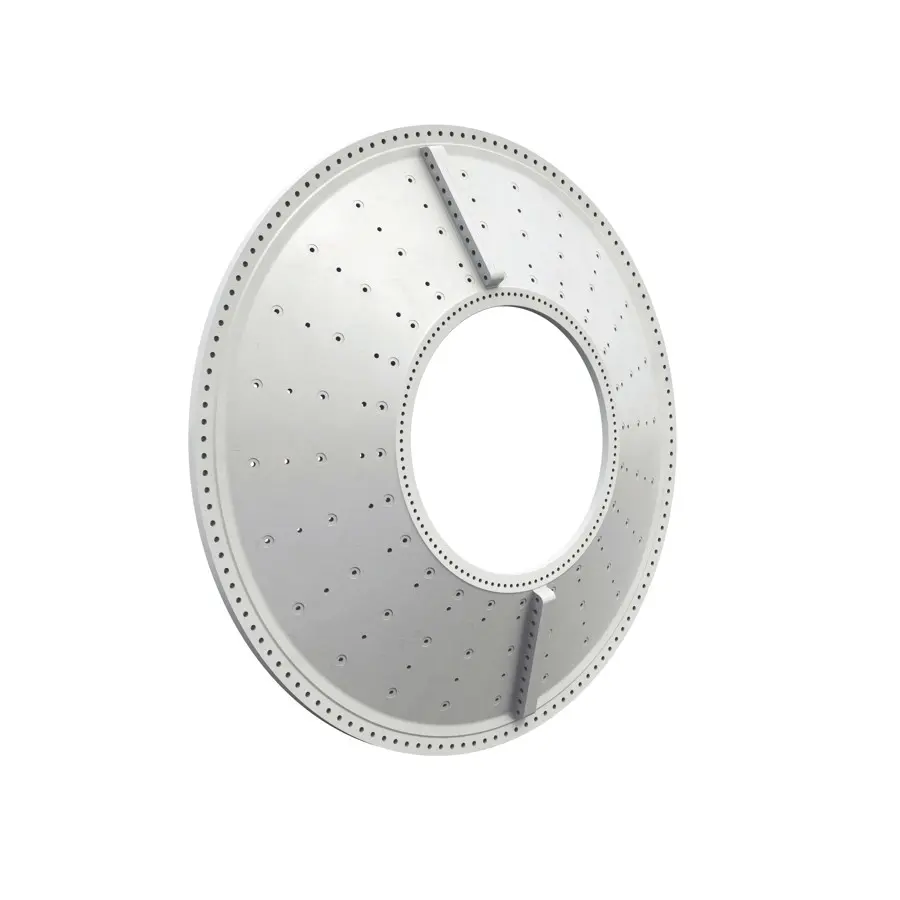
Part scope Shell connection rim Transfers shell loads and establishes end-face and hole geometry Trunnion interface Connects journal support and feed/discharge passages Liner mounting surface Supports head liners, lifters and fasteners Segmentation and location Control transport, installation, interface stiffness and concentricity
The head carries structural loads and must be distinguished from head liners and the trunnion
The outer rim connects to the shell, the centre connects to the trunnion, and head liners mount inside. These adjacent parts differ in function, material, hole patterns, machining datums and acceptance requirements.
Before ordering, establish whether the head and trunnion are separate or integrally cast. Check the shell flange, main bearing centreline, feed/discharge arrangement, liner holes and seal interfaces together.
Position and Performance
Control load paths, interface accuracy, internal integrity and liner holes together
Identify the head around the rotation centreline and adjacent assemblies; external shape alone is insufficient.
Shell connection flange
Check outside diameter, register, end face, hole pattern, bolt circle, bolt preload, concentricity and interface stiffness.
Trunnion connection area
Check integral or separate construction, central bore, flange, transition radii, journal orientation and machining datums.
Head liner hole pattern
Check inner and outer rings, liner profiles, fastening holes, lifters, grates or overflow-end configuration.
Transition radii and heavy sections
Carry cyclic loads. Control abrupt geometry changes, shrinkage cavities and porosity, inclusions, cracks and machining marks.
Feed and discharge ends
Feed arrangements, discharge structures, trunnion liners, seals and trommel interfaces may differ. Do not assume interchangeability.
Fixed and floating ends
Match the main bearing axial-location and thermal-expansion arrangement, and establish orientation, position number and assembly datums.
OEM Structures and Specifications
Material, segment count and end position are part of the order specification
Manufacturer literature supports preliminary identification. Confirm the installed design using drawings, serial number and revision.
Establish grade, composition, mechanical properties, heat treatment, weld-repair rules, non-destructive inspection levels, dimensional tolerances and surface requirements through drawings and technical agreements. Images alone cannot identify the material.
Failure Diagnosis
Assess cracks, hole damage and interface deviations against complete-machine loads
When head damage is found, also inspect the trunnion, shell, main bearings, liners, fasteners and alignment.
| Observed condition | Priority checks | Improvement Options |
|---|---|---|
| Cracks at the trunnion transition or in the head | Cyclic loads, radii, casting defects, machining marks, alignment, bearings and abnormal impact | Assess material and cracks, and restore load paths and interfaces |
| Shell-flange hole damage or face runout | Hole pattern, register, preload, contact surfaces, transport and lifting, assembly sequence and shell distortion | Restore locating datums, hole patterns and flange connection quality |
| Worn liner holes or local cracks | Loose liners, fastener preload, hole spacing, shims, impact direction and remaining head section | Check liners, fasteners and head hole areas together |
| Loose or stepped segment joints | Segment location, connectors, contact surfaces, preload, concentricity, site assembly and operating records | Restore segment datums and reassemble in the specified sequence |
| Central bore or trunnion interface deviations | Integral/separate construction, centreline, concentricity, flanges, bearing elevations, machining datums and repair history | Coordinate machining and site installation around the rotation centreline |
Drawings and Inquiry Details
Identify heads by end position, segmentation, assembly relationships and key interfaces
Provide the drawing, sample, model details or customer drawing for the installed component, and confirm the revision.
Equipment identification
OEM, series, complete model, serial number, shell diameter, EGL, power, speed and modification history.
End position and structure
Feed or discharge end, fixed or floating end, integral or segmented construction, segment count, and integral or separate trunnion.
Drawing and Revision
Head drawing, rotating assembly number, trunnion number, drawing, model details, drawing revision and physical markings.
Shell interface dimensions
Outside diameter, register, end face, thickness, hole diameters and spacing, bolt circle, face runout and contact surfaces.
Central and internal interfaces
Central bore, trunnion flange, concentricity, liner holes, feed/discharge structures, seals and adjacent assemblies.
Materials and inspection
Material, heat/batch, heat treatment, mechanical properties, casting records, UT/MT/PT, dimensional reports and repair history.
Related Equipment and Parts
Connect heads with liners, trunnions, shells, equipment and OEM installations
General pages explain part boundaries and manufacturing requirements; OEM pages identify the installed series. Drawing or sample, dimensions and inspection requirements complete the technical checks.
End Liner Check internal wear protection, hole patterns and installation positions. Trunnions Check central interfaces, journals, end positions and fixed/floating arrangements. General Ball Mills Information Review the relationship between heads, shells, trunnions and main bearings. Metso Select / Premier Ball Mills Check series, dimensions, end positions and installation drawing. FLS Ball Mills Identify heads through the brand series and installation information. Materials, Manufacturing and Inspection Review large casting materials and quality-control requirements.
Request a ball mill head proposal and quotation
Provide the mill model, end position, segment and assembly drawing, interface dimensions, material, NDT requirements and damage records.