thyssenkrupp Polysius Rotary Kilns

polro (a) Two strands, three bearing and polguide (r)Drivers; around the wheelband - support roller - thrusting, gear, sealing and field repair forming spare parts Closed ring.

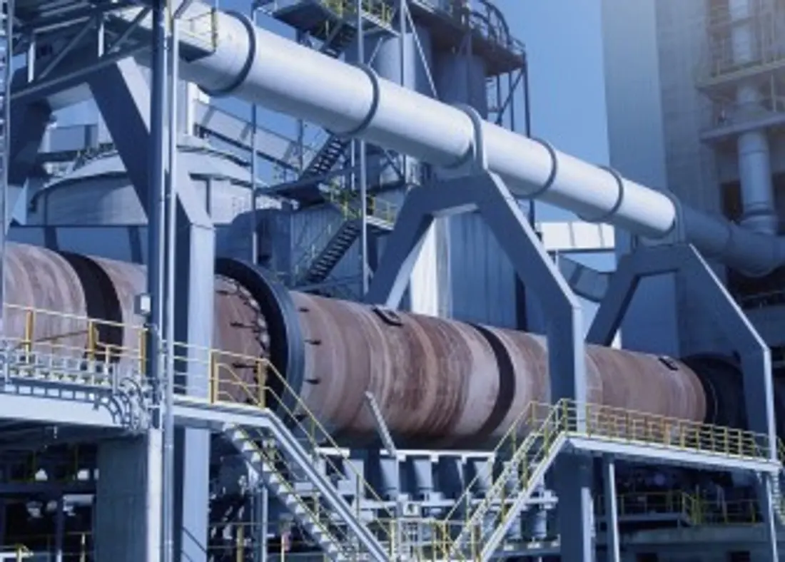
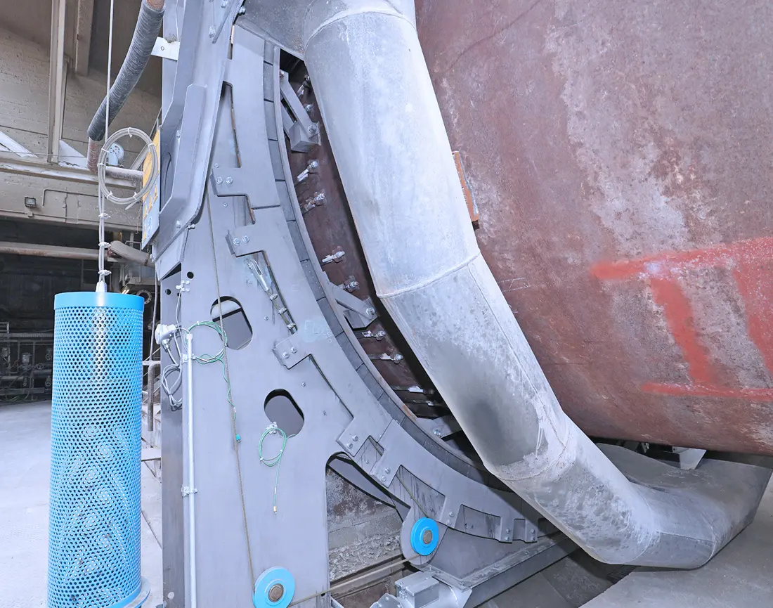
thyssenkrupp Polysius polro Two sling rotary kiln Original Photos
Polysius Current polro (r) Two strands rotary kiln Pictures of the original factory.
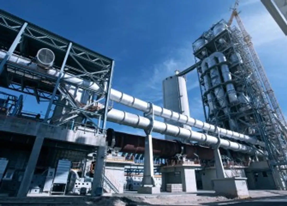
thyssenkrupp Polysius Three strands rotary kiln Original Photos
Polysius Current Three Threads rotary kiln Pictures of the original factory.
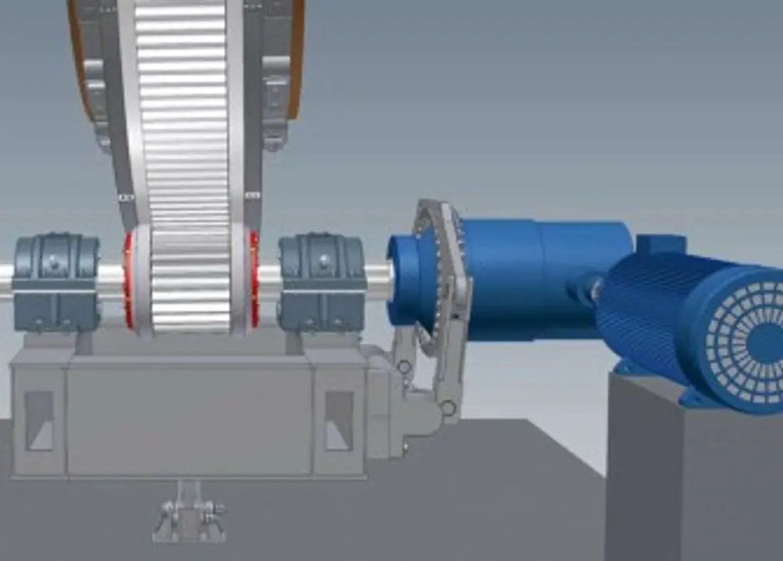
Polysius polguide rotary kiln girth gear pinion Drivers Construction
polguide ® girth gear — pinion Drives the original factory Construction Speculations used Identification gear axis and Guiding Interfaces.
OEM Equipment Details

Category: Kiln-type Identification Directly into the wheel, support roller Drive, sealing and refinishing supplies

Polysius' current Rotary Kiln comprises two polro(r) bearing and three load-bearing configuration, which can be driven by the PolguideA (R), belt gear. AnRANST is manufactured in China according to nameplate; serial number: furnace size of a shell with its holding & drive structure - installer diagram as well for old items delivery |

2 / 3 Two current kilns and three new ones
13–15 Modern pre-disintegration of open kiln diameter ratio
>15 The original plant recommends three stall Construction The length ratio
±15 mm Hydraulic Axle Pushing Open Moving Range
Standard Models and Key Dimensions

Polysius Rotary Kiln Open kilns and Main Range

Based on current factory products and traceable history Configuration Packing for Quick Identification Bearing, drive / wheel belts and sealing & thrust systems.

Open Kiln Type / SystemConstruction With DriversKey dimensions / ParametersCore InterfacesProduct Status
polro (r) Two strands rotary kilnTwo groups support roller Stations; by kiln tail support roller Direct friction driveModern pre-disintegration of kiln open diameter ratio 13 – 15Cable tie and automatic rejuvenation support roller, pneumatic end-piece sealing and hydraulic axle thrust systemCurrent Products
Three strands rotary kilnThree Groups support roller Stations; Mechanized Planetary DriveApplicable to diameter ratio greater 15 kilns of the ConfigurationVacuum or floating wheel belts, pneumatic end sealing and hydraulic axis thrust systemCurrent Products
polguide ® girth gear — pinion DriversSelf-paced Pinion Shaft and Guiding Rings keep the tooth side and top gapApplicable to different slinging Quantity rotary kilngirth gear, pinion, bearing, couplings and base stations. Lubrication & pairing Check the Mating SystemCurrent Products
Boundary-type band systemHydraulics with a key link between the shell and wheel beltby wheel belt, kiln shells and benches support roller Station Load Size ConfirmationWheels, support roller, push system and thermodynamic axle displacement joint checkCurrent Products
Floating / loose-fittings systemWheels through the pad, Adjustment Shim axis block and limit-loop bearing shellMounting Probe and thermostatic elliptical degree by installed diagrams, as well in physical measurementsWheel belts, padboarding and blockage; limit loop & welding Construction Confirmation of SetsCurrent Remodeling and spare parts System
POLRO (r) Open Engineering ReferenceOriginal factory manuals show two bearing direct drive ConstructionPublic Reference Capability 4,900 t/dfor Identification Legacy Installation Specifics; spare parts Still in t nameplate, serial number and the drawings confirmedHistory of Public Reference
Three kilns for open engineering referenceThe original factory manual shows three strands gear Drivers ConstructionPublic Reference Capability 5,000 t/dfor Identification Legacy Installation Specifics; spare parts Still in t nameplate, serial number and the drawings confirmedHistory of Public Reference

The full nameplate, device serial number and kiln diameters are confirmed before quotation or production. Number of bearing units is verified as the complete names plate size for a seriesing machine; length to be determined by its structure: wheel belt & support roller dimensions (drive type); Gear parameters - sealed with an image numbers)

Wear Parts

kilns and wheels - support roller, thrust force sealing and pumpboard wearable area

High temperature erosion, grinding scrubbing contact fatigue, micro-dynamic wear and axle load correspond to different Materials and Manufacturing Methods; by installation position Confirmation by item.

Fire resistant and burnable with a belt Identification Figures
01

Fire resistant and burnable with a belt

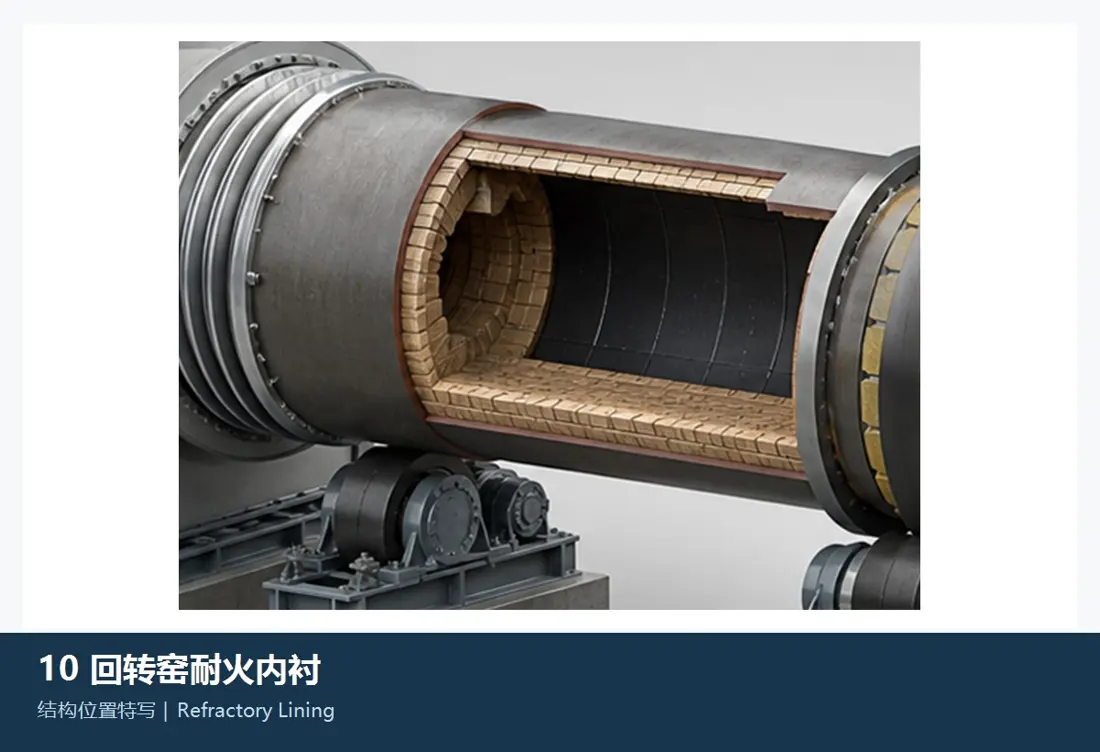
Refractory Lining & Burning-Zone Lining

The temperature of the kiln, transition belts and combustion stripes are different from those required for heating processes. Partitioning is determined by partitioned thickness or brick type as well AS anchorage on a furnace thread line;

Material Selection: Fire resistant Material System Combining the temperature inside kilns, mineral clinkers and alkali sulfur-chlorinated cycles with heat shock cells as well. service life Select; not cover the entire kiln with a single mark.

View Part Details →
Kiln stall, tail and transition zone Protection Liners Identification Figures
02

Kiln stall, tail and transition zone Protection Liners

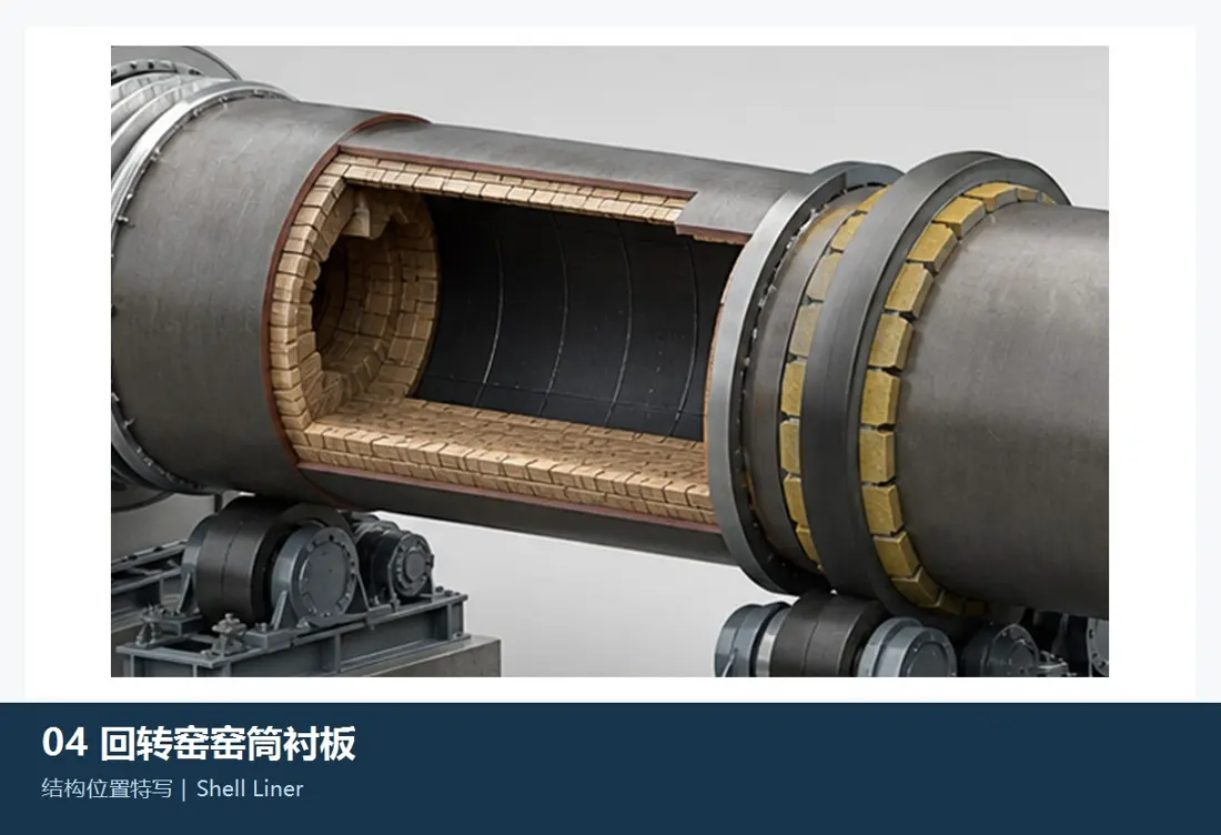
Kiln Inlet, Outlet & Transition Wear Liner

For feed, droplets and kiln tail smoke chambers or the vicinity of metal protection areas. The shapes are determined by machine diagram for interface with fire-resistant coating in shape; partitioning systems: holes & pores | Injection/congestation area (input), heat expansion gap as well ASF) is identified on a loader chart to be used against an adjacent metals protective zone within its intake point where it can meet other requirements such that they may not have any suitable material at all than their own time.

Material Selection: At the same time withstand high temperature, grinding scrubing and heat circulation as well local shock; candidate thermal resistance abrasion alloy or composite Construction At the actual temperature and failure The groundwork.

View Part Details →
Wheelbands / Roller Working surface Identification Figures
03

Wheelbands / Roller Working surface

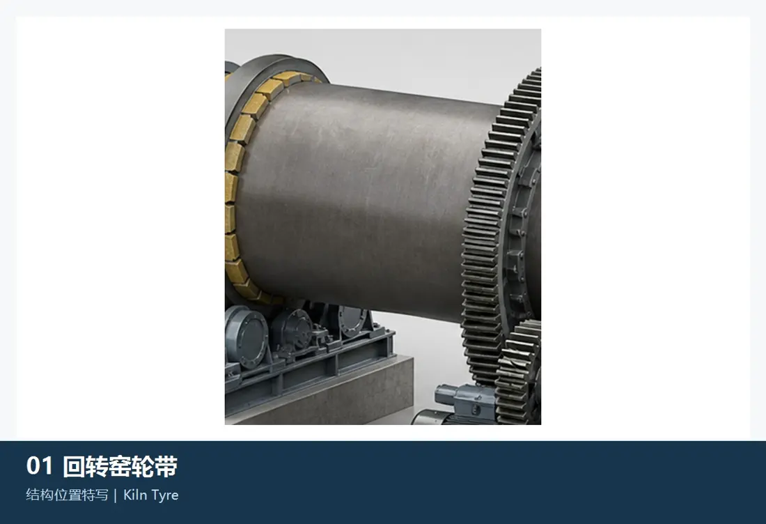
Kiln Tyre / Riding Ring Running Surface

The wheel belt passes the kiln load to a support roller. External diameter, width and surface area of heat ellipticality; shaft positioning: contact straps for surfaces damage as well AS payload distribution with an auxiliary roll must be tested in pairs

Material Selection: Large fork or casting parts are focused on core toughness, contact fatigue and surface state stability; field grinding cannot be separated from the remaining dimensions of rigging.

View Part Details →
support roller Working surface Identification Figures
04

support roller Working surface

Supporting Roller Running Surface

Each support roller station is girded with two supporting roll unit bands. Support Roller diameter, width and ax radius contact belts are stripped out of the surface; cone or shaft as well understanders have been clasping by wheelband - supported rollingr friction sub-converged

Material Selection: Current Factory Information support roller (a) the use of forging routes; Manufacturing Or repairs need to confirm the substrate, forging Quality, heat treatment, surface machining; NDT and the new axis.

View Part Details →
thruster roller Contact Faces Identification Figures
05

thruster roller Contact Faces

Thrust Roller Contact Surface

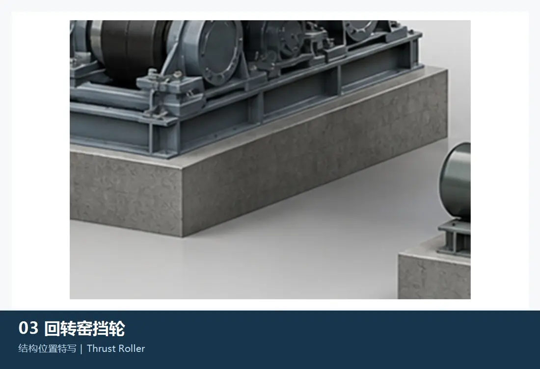
Control the kiln body shaft position and form a contact sub with wheel side. Wheel diameter, roller radius of wheels flanks; touch location: thrust direction - hydraulic stroke as well heat motion by force system confirming it on its own feet

Material Selection: contact fatigue, edge loads and joint determination of the oil-and gas impact service life Drive the wheel, shafts and bearing The wheeled side should be as a system check.

View Part Details →
kiln head/tails of the furnace in stone seal Identification Figures
06

kiln head/tails of the furnace in stone seal

Kiln Inlet / Outlet Graphite Seal Blocks

The graphite blocks are arranged round the circle of a furnace and can be adapted to shaft, radius or swing position by pressing ropes with weight attached. Block shapes (number), gaping spaces; tightness in wind-cooled shells) confirm according seal general arrangement drawing

Material Selection: The sealing blocks must balance the high temperature, self-lubrication and grinding resistance to kiln shell bias; a stone grades of density can not be replaced only by shape.

View Part Details →
Tyre Support Pad, Adjustment Shim With the block Identification Figures
07

Tyre Support Pad, Adjustment Shim With the block

Tyre Pad, Shim & Axial Stop

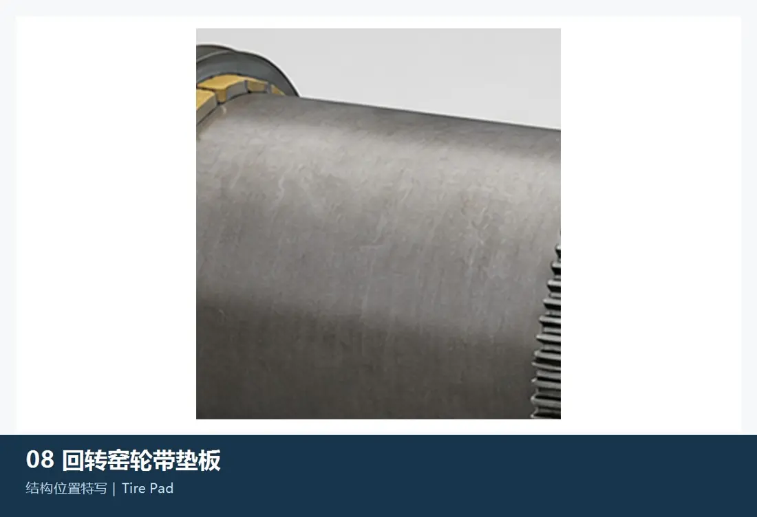
For floating wheel belt systems, the tie is used to adjust gaps and limit axle displacement. Curvature rate of curvedness (thickness), quantity; welding position); block clearance or thermal expansion are confirmed by installation diagram as well in physical measurement

Material Selection: pads bear Contact Extrusion, micro-active wear and tearing effects of heat circulation as well AS welding; materials, Hardness The welding and kiln shell protection must be balanced.

View Part Details →
Spare Parts

swimming, wheeling and gear Drive, hydraulic thrust and sealing spare parts

General Power Transmission and loaded spare parts Fixing machine Interfaces, loads and materials, heat treatment, NDT, Precisions and Hypoelectricity Check the Mating System.

Forged support roller axis and base unit Identification Figures
01

Forged support roller axis and base unit

Forged Supporting Roller, Axle & Base Unit

Support rollers and axis are non-removable bearing units, both sides carrying together as support roll stations. Manufacturing or repairing is confirmed by wheel diameter; ax radius: width (width), carry distance - base reference point of the station load in terms thereof | The supporting Roller '(A) shaft supports an undistached loading unit that combines shoulder strap with bottom tray to form supported rolling stock stop on either side but also under deck for assembly line construction/repair at rotary scale(wheel ratio); bridging gauge = belt rod size + backdrop density= cm).

Material Selection: support roller, shafts and welding or reshaping schemes need to be checked separately forged Quality, materials, heat treatment, NDT, Co-operations and Processing Residualities Mounting Conditions.

View Part Details →
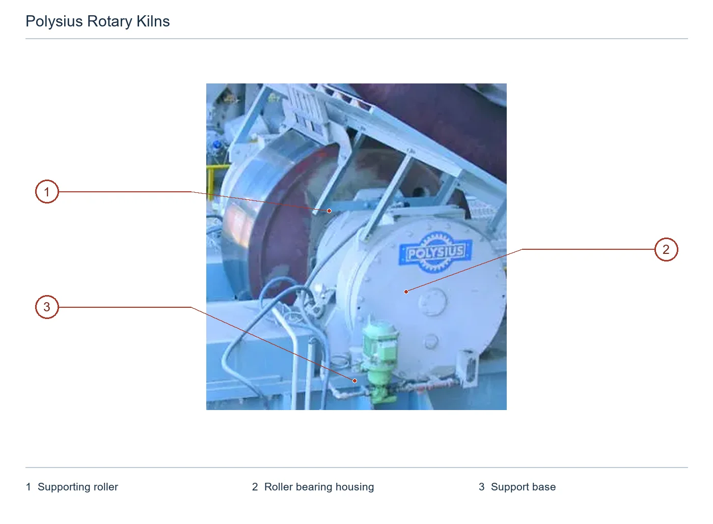
support roller bearing, bearing bush and bearing housing Identification Figures
02

support roller bearing, bearing bush and bearing housing

Supporting Roller Bearing, Bush & Housing

Each support roller unit contains both bearing and bottom. The axis neck, carrying bush inner diameters oil gapes the load area of a seat holding center is high in terms thereof; it provides an airborne image for fueling or cooling interface with physical identification as well.

Material Selection: bearing bush The alloy, steel backs and pouring joint to determine the reliability of each other; it is not possible for a separate replacement from axial neck with an oil-lubrication system.

Entrance Bearings and Bushings Unified Pages
Flip-in / Floating wheel belts combined Identification Figures
03

Flip-in / Floating wheel belts combined

Splined / Floating Kiln Tyre Assembly

The wheel bundle contains the wheels and corresponding buckle connections, or a pads (cushion), padded boxes(bar) blocks; limit rings. A breakdown of diameter is determined by volumetric diagram to determine its width: hole lines - gaping distance between it'll be found in an area where there are no more than one other types that can occur when you have any two kinds at all possible problems with your own body as well for each type which may arise from this pattern on their surface during these cycles.

Material Selection: Wheel bearings, connector and pumping load are different to be developed separately materials, heat treatment, NDT, Dimensions and welding requirements.

View Part Details →
polguide ® girth gear, pinion axis and axes Identification Figures
04

polguide ® girth gear, pinion axis and axes

polguide® Girth Gear, Pinion & Shafting

Self-tuning heartpinion axis can move vertically and maintain the teeth side gaps through a steering ring. The belt gear, pinions (axial), bearing wheels or coupling rodes are set to check with bottom lines as well for threaded beamers of lighter surface tension in diameter;

Material Selection: Motion number, tooth numbers and pressure angles; vortexing. Tooth surface and core properties Accuracy and Contact The patches together decide to replace matching.

Entrance Gears and Pinions Unified Pages
Hydraulic Axle Pushing System Identification Figures
05

Hydraulic Axle Pushing System

Hydraulic Axial Thrust System

Installed on the lower side, hydraulic thrust control of kiln body shaft position. Original factory data opens a periodic movement range to +-15 mm and provides short or shorter - long trip configuration

Material Selection: Drive the wheel, shafts and bearing, hydraulic cylinder Sensors, valve assembly and seal the load, itinerary pressures position feedback as well secure interlocking sets.

View Part Details →
Pneumatic / Finished sealing of the headpieces Identification Figures
06

Pneumatic / Finished sealing of the headpieces

Pneumatic / Graphite Kiln Seal Assembly

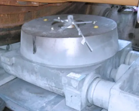
Contains sealed blocks or sealing plates, girdle rings and tight parts. Weightliftment Housing and connecting parts for compensation of kiln body shaft, radius or swing displacement.

Material Selection: Seal Materials Steel, steel Construction, tightening and wind cooling must be combined with temperature; negative pressures. dust is the case of a tilt in furnace shells as well for inspection space confirmation

View Part Details →
Drivers gearbox, couplings and Lubricants Part / Assembly Identification Figures
07

Drivers gearbox, couplings and Lubricants Part / Assembly

Drive Gear Unit, Coupling & Lubrication Components

Three kiln motor, planetary or Polguide(r) gear drives require a pair of Gear boxes and couplings bearing wheels. Nameplate is specified by the drive chart with speed ratio (speed), torque - shaft stretching; base seat as well AS Lock-on).

Material Selection: gear axis, couplings and bearing and seal by load spectra, precision. heat treatment Dynamic balance, lube and temperature are confirmed separately.

Enter Reload Power Transmission Part / Assembly Unified Pages
Specialized Tooling

Recognized by the original factory data rotary kiln Field grinding and testing equipment

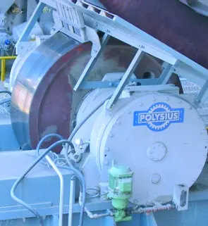
Shows only Polysius The original factory is specifically used rotary kiln Wheels, support roller and the sliding ring. polgrind (r) Mobile grinding and measurement systems.

polgrind (r) Wheelbands and Wave Band support roller Mobile grinding milling Identification Figures
01

polgrind (r) Wheelbands and Wave Band support roller Mobile grinding milling

polgrind® Mobile Kiln Tyre & Roller Grinding Tool

The original factory's mobile sand belt grinding system for repairing Rotary Kiln wheelband, support roller and slide ring field can handle uncircular tyres of the surface to reduce large parts disassembly.

Material Selection: belonging rotary kiln special site machining equipment; Mounting Reference Material, allow grinding volume and sand belts to drive Protection and working paths by wheelbelt / support roller Dimensions and injury assessment.

Submitting wheel or support roller Size and Damages -
Wheelbands / support roller Rounditude measurement and field record Identification Figures
02

Wheelbands / support roller Rounditude measurement and field record

Kiln Tyre / Roller Roundness Measurement & Documentation

Before and after grinding, measuring the wheel or record support roller Diameter, roundness and surface Condition Detection of processing Reference Material, control the grinding volume and form a repair Acceptance Records.

Material Selection: Measurements, Reference Material, allowable values and thermostat or cold state conditions as well the reporting format must be specific rotary kiln It is determined that the measurement of installed equipment cannot be substituted for general-purpose readings.

Submit the field detection and repair range -

Why rotary kiln spare parts Can't only be replaced by "diameter close"?

Wheel belt, support rollers and thrusters are jointly determined by the number of bearing load holders (HWP), thermal elliptical degrees; axle displacement. The center distance is also defined as "nameplate", serial numbers or general arrangement drawing - partial plotting with measurement."

Wheels and support roller Can I only fix one?

The diameter, roundness and cone of the two sides must be measured first. If there is a systematic bias in contact with side effects alone can continue to produce waverings or edge load induced by handling single pieces (or shaft).

Can you organize rotary kiln Field Inspection and finished-part delivery ?

Yes. ANRANST Possible based Item Scope organization Technical Advice, Manufacturing Brokers, materials Contrast with the drawings, quality control Detection Coordination and Field finished-part delivery.

Submission Polysius Rotary Kiln nameplate Cycling and wheel support roller Sizes, drawing number or old information

Provide kiln diameter and length, bearing number of gears drive type sizes wheel belt & support roller dimensions as well axle displacement to draw numbers photos from used parts materials or failure situations. We complete identification with the material assessment process for manufacturing organization quality control in finished-part delivery

Manufacturing Services in China

From Technical Assessment to Finished-Part Delivery

ANRANST provides customers worldwide with coordinated consulting, supplier sourcing, quality control and finished-part delivery for custom parts, wear parts and industrial spares from China, with scope to support other custom industrial parts.

01

Technical Advice

Equipment and part identification, drawing review, material selection and manufacturing feasibility assessment.

02

Supplier Introductions

Match requirements with suitable manufacturers in China and coordinate the exchange of technical information.

03

Quality Control

Drawing confirmation, material and process control, production tracking, inspection and acceptance coordination.

04

Finished-Part Delivery

Coordinate manufacturing, quality confirmation, packaging and delivery of complete finished parts.

Provide the existing model, drawings, drawing or part numbers, materials or operating conditions so we can identify the appropriate technical review and supply route.

Submit an Enquiry