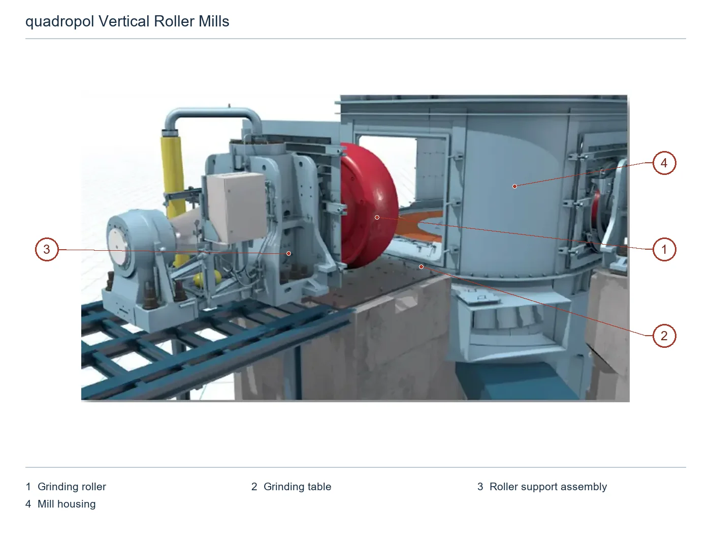
thyssenkrupp Polysius quadropol® Vertical Roller Mills

QMR ², QMK ², QMC and QMS ² Installation Identification circling around grinding roller, grinding table, Nozzles Rings, bearing Hydraulics and drive formation wear parts and spare parts Closed ring.

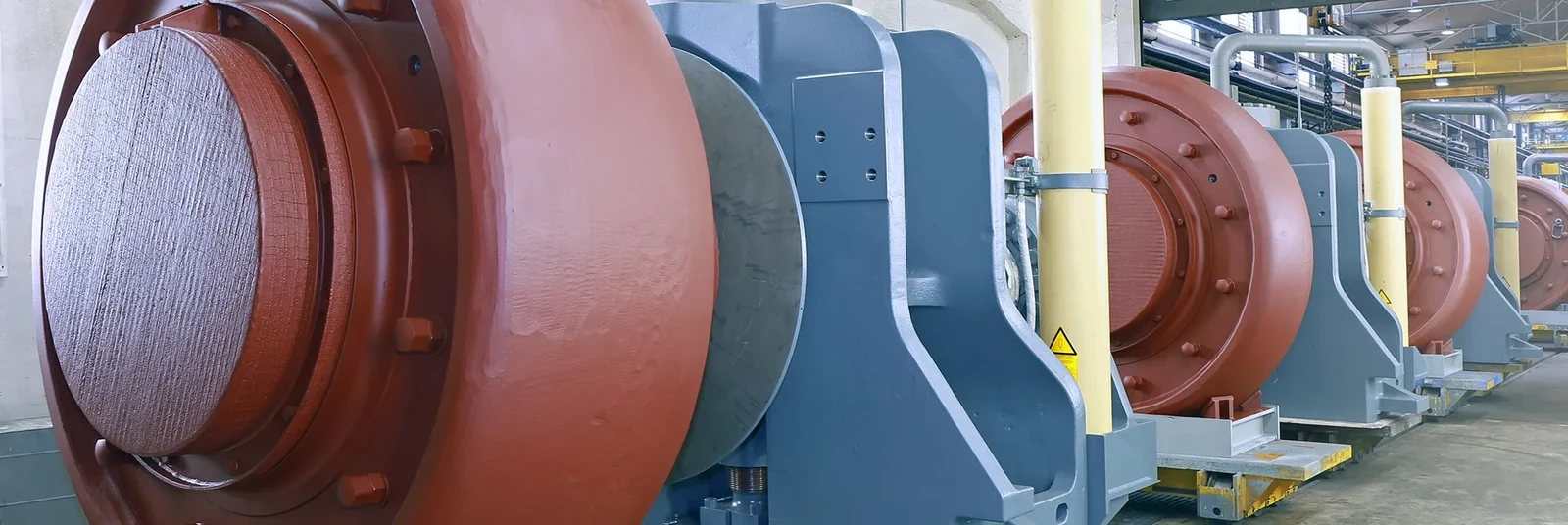
thyssenkrupp Polysius quadropol Pre-assembly grinding roller Units Original Plant Map
Original Factory quadropol (r) Pre-assembly grinding roller Units that clearly show roller body, liner and hydraulic cylinder and Interfaces.
quadropol grinding roller Units to extract original factory pictorial illustration
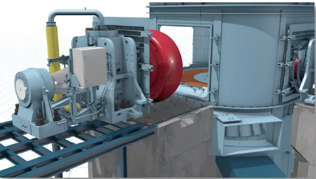
Original Factory grinding roller Modules for repairing the layout Identification Roller Units, Housing Openings, tracks and transshipment Interfaces.
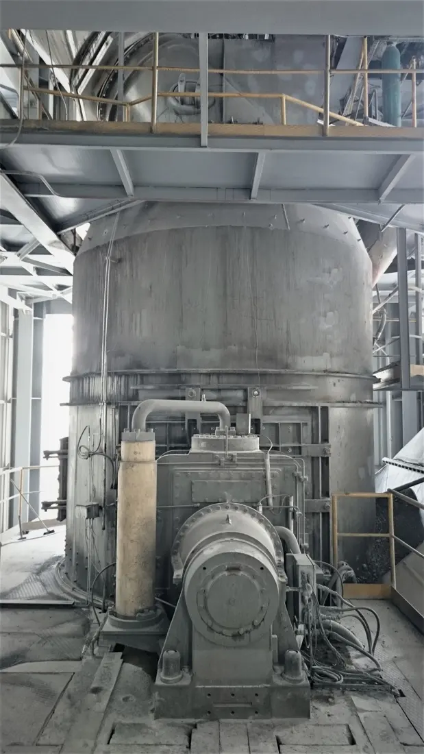
quadropol QMK Pictures of the original milling site
Original Factory QMK Coal Milling Fields for Identification Housing, grinding roller Units, hydraulic and drive areas.
OEM Equipment Details

Equipment Series Packing Model The number and the parts are centered on one page.

Quadropol(r) uses modular roller units and is configured by material or project. This page lists only the original series of models with installed model, not knowingly interpreting their size; Spare parts manufacturing still depends on nameplates / serial numbers (or number), layout maps as well for actual interface to be used in this case

4 Current Open Apps Series QMR ² / QMK ² / QMC ² / QMS ²
9 Verified in the public specifics Model No
2–6 Original factory manual open modular roller unit Quantity Scope
< 2.0 mm/s Current Official Site mill Vibration levels
Standard Models and Key Dimensions

quadropol ® Equipment Series Equipment Series and Installed Models

model from the current Polysius Product pages, References Item and QMR ² / QMC ² / QMK. Original factory manuals; unpublished complete model Tables are not calculated.

Series / Public modelCore UsesPublic Installation IdentificationBases for reconciliationProduct Status
QMR² 38/19Raw millingBolivia Oruro, 3,000 t/d scrub lineCurrent References for Original Factory ItemCurrent Products
QMR² 43/21Raw millingMexico, Brazil Open-towerQMR Original Factory ManualSecond-generation products
QMR² 45/23Raw millingTurkey Afyon, 4,000 t/d scrub lineCurrent References for Original Factory ItemCurrent installer
QMR² 48/24Raw millingKenya Mombasa Saudi Arabia YamamaCurrent References for Original Factory ItemCurrent installer
QMC² 40/20Cement / Coal materials millingDominica Cementos CibaoCurrent References for Original Factory Item2021 Operating from year
QMC² 45/23Cement / Coal materials millingBolivia Oruro - Turkey AfyonCurrent References for Original Factory ItemCurrent installer
QMC² 51/25Cement / Coal materials millingGuatemala Cemento Progreso, 2 taiCurrent References for Original Factory ItemCurrent installer
QMK² 24/12Coal / Oil Foam MillKenya Mombasa, 3 One Roller UnitCurrent References for Original Factory ItemCurrent installer
QMK² 32/16Coal, oil coke or lignite millIndia, Indonesia and TurkeyCurrent References for Original Factory ItemCurrent installer
QMS ²(Equipment Series)Mint MillingThe public page does not specify the size modelby nameplate and Item Drawings IdentificationCurrent Product Categories

Manufacturing Prior confirmation complete model, nameplate, serial number, Roller Unit Quantity, grinding table and grinding roller Sizes, TD / RD Driver, graders and drawing number and Drawing Revision.

Wear Parts

grinding roller, grinding table, Nozzles Rings and groove wear parts

Different installation position Pressure, shocks and abrasive wear, airflow brushing and heat loads are different; materials, Wear Layer and Manufacturing The process is confirmed separately by location.

grinding roller roller tyre / Roller tires Identification Figures
01

grinding roller roller tyre / Roller tires

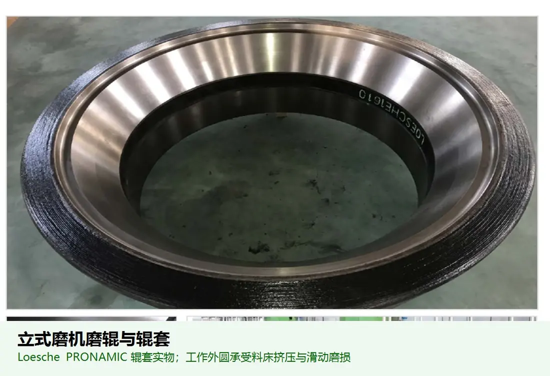
Grinding Roller Tyre

Direct pressed and powdered bed is the core wearable of Quadropol(r). The shape, working surface area (or interior hole), key or clamping structure - roller unit position as well for abrasion are confirmed by installation diagram.

Material Selection: Abrasion of raw materials, clinkers and mines are different from impact; wear-resistant cast iron or alloy steel systems can be assessed as well for controlling the hardness in cores.

View Part Details →
grinding table Liners / grinding table Val Identification Figures
02

grinding table Liners / grinding table Val

Grinding Table Liner / Segment

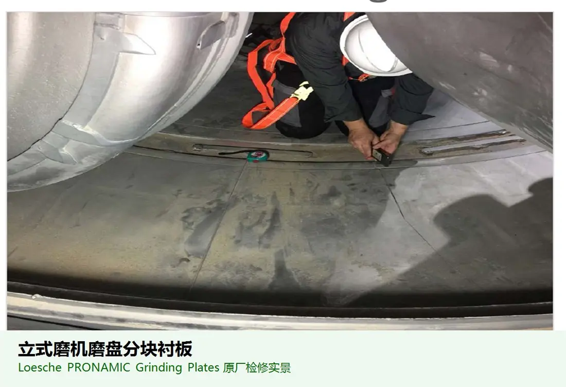
The rotating grinding table is composed of a slab and the milling roller forms feed bed. A set must be assembled for batches, surface surfaces or thickness; fixed holes are located in inner circles as well inside them: an interface with gear loop to resistors shall also form wearable template on which they can meet their needs

Material Selection: High wear casting, alloy steel or hard surface composite solutions are selected according to exposure pressures and abrasion wearing resistance as well heat circulation; stitching is the focus of receiving location.

View Part Details →
Nozzles Rings / Wind-conducting rings Identification Figures
03

Nozzles Rings / Wind-conducting rings

Nozzle Ring / Louver Ring

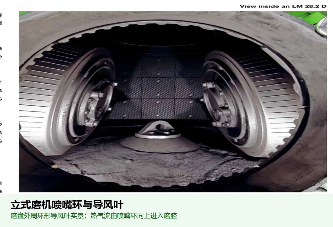
The angle of the blade, flow area and segmentation are adjusted around grinding table to adjust upstream airflows with materials.The gap between a leaf pad is determined by shell & process configuration; its diameter: inlet size () or outside radius - fixed mode as well AS clearance from milling tables

Material Selection: High-speed dust airflow, grinding scrubber and local heat load can be used with wear resistance steel plate or alloy steel (or locally composite reinforcement) to focus on the edge of bladed areas.

View Part Details →
Feedback loops/Keep rings Identification Figures
04

Feedback loops/Keep rings

Dam Ring / Retention Ring

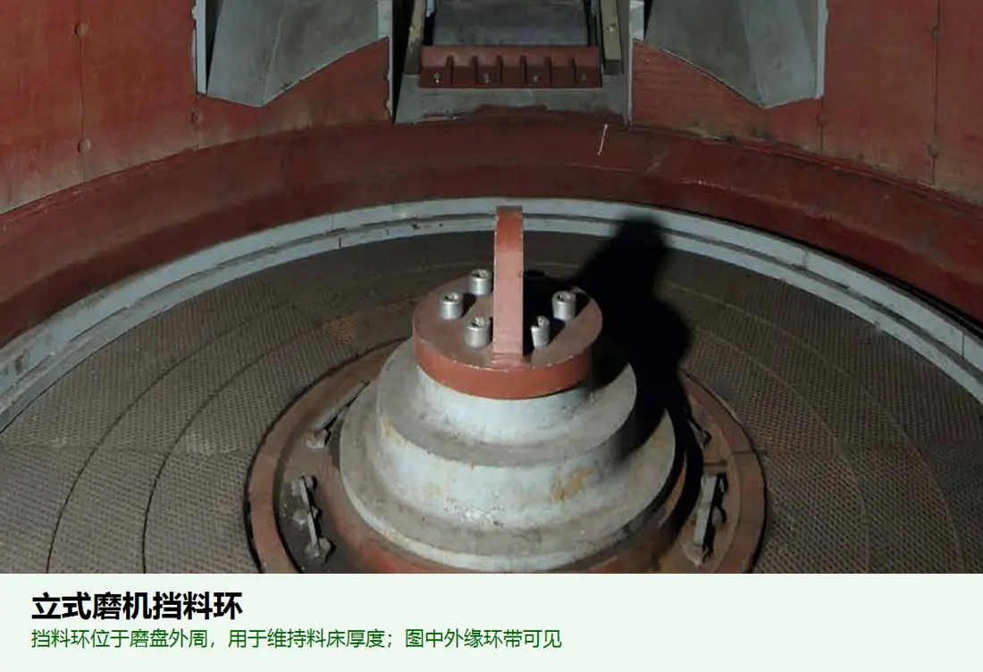
Controls grinding table The edge of the bed thickness and stability grinding process. Height, segmentation radii Interfaces, grinding table Location and adjustment Construction Need to be specific QMR ², QMC ², QMK or QMS.The installed response

Material Selection: The edge area also endures sliding wear, extrusion and shock. Materials need to balance the abracibility of resistance resistantness with toughity as well for maintenance; changes in size will affect feed bed can not be only imitation by shape

View Part Details →
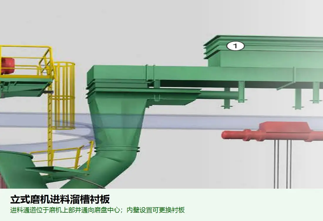
Feed-chute liner identification image
05

Feed Chute Liner

Feed Chute Liner

The protection center feeds and droplets can withstand blockage shock, sliding wear & dump. Contouring cordial system of holes in the area is determined by a slot chart relative to grinding table centre location

Material Selection: Selected according to the raw material block size, moisture content and fallout ratios. wear-resistant steel plate, elastomers or Composite liners, and the school sealing of materials to removes from them as well.

View Part Details →
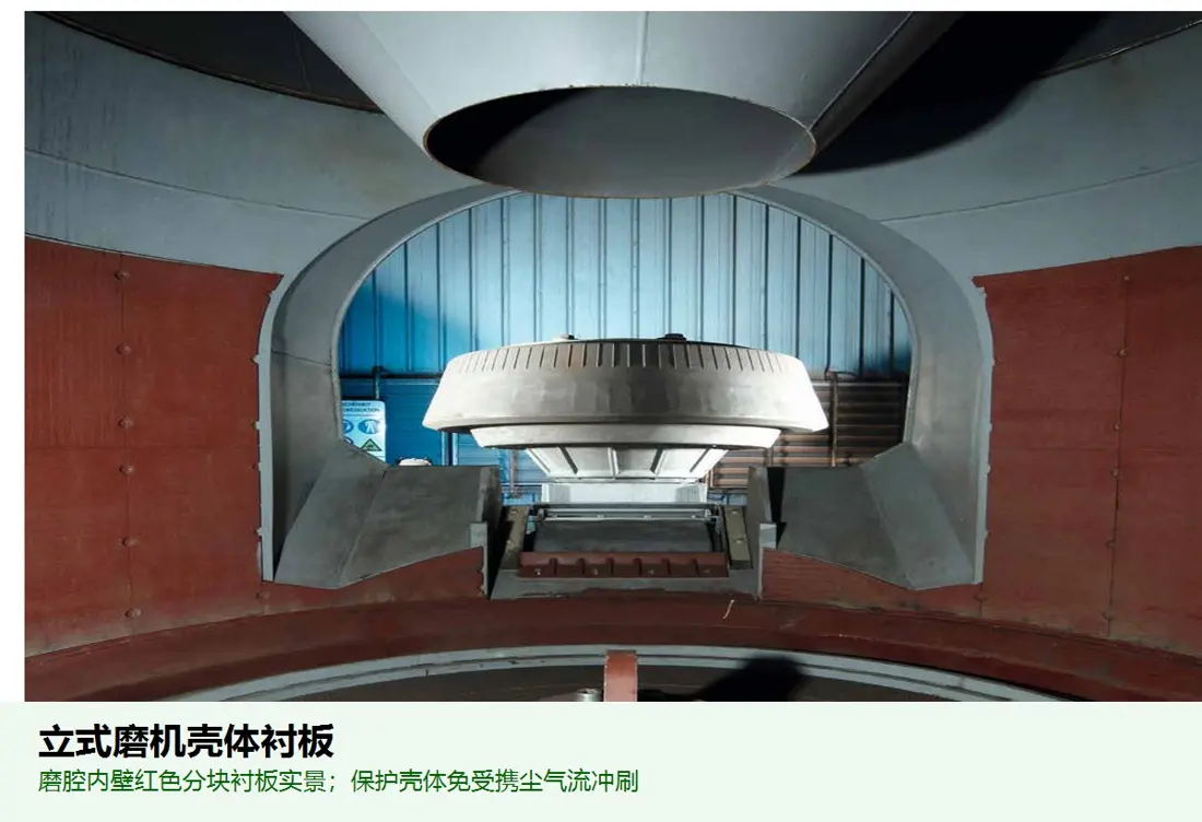
Mill Shell Liner Identification Figures
06

Mill Shell Liner

Mill Housing Liner

Protection of the grinding chamber shell, inspection doors and dust airflow areas. The partitioning area scrutiny lineage is determined by a pattern for sealings to be arranged in sectional format; holes are fixed or sealed with welding valve as well AS FLOWS ARE set up on an image from which it will appear that its direction shall not exceed one hundred per cent ().

Material Selection: Low impact swimming area can be used wear-resistant steel plate or composite board; local high impact areas need to improve the substrate toughness, and control plate thickness.

View Part Details →
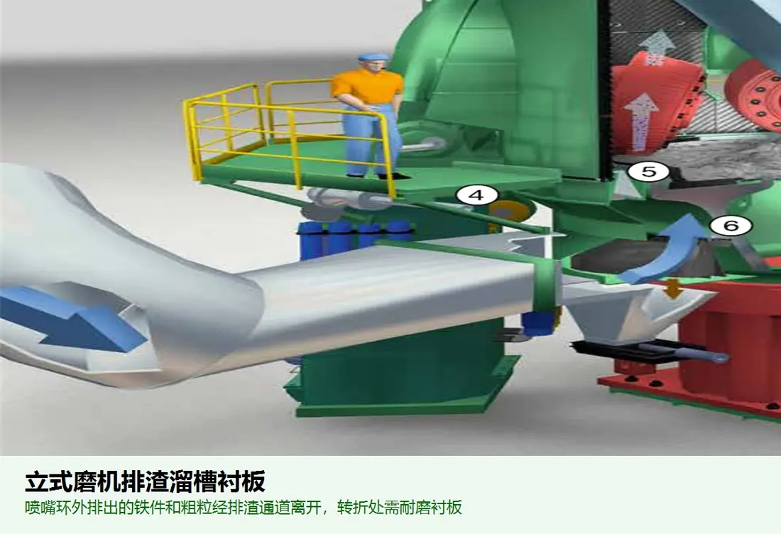
Recycled Material / Reject Chute Liner Identification Figures
07

Recycled Material / Reject Chute Liner

Reject Chute Liner

Protection of the crude particles, metal aliens and dumping material channels that are not taken away by airflow. The drop point or cornering is confirmed on a system diagram for falling points (or angle), doors/door bodies; spliced holes & bottom conveyor interface).

Material Selection: Feed impact zone Separates from sliding Material Selection. which can be evaluated wear-resistant steel plate Strength and Resilience alloy steel Or elastic Composite liners and retains the repairing space.

View Part Details →
Spare Parts

Roller Units, bearing Hydraulics, drive and grade spare parts

General Power Transmission and Function spare parts by Series, Interfaces, loads and Speed, materials, heat treatment, NDT, sealing and melting the balance of each item.

Pre-assembly grinding roller Units Identification Figures
01

Pre-assembly grinding roller Units

Pre-Assembled Roller Unit

The number and structure of the rollers, roll axis (Roll shaft), spindle bearing(r) wheeling loaders; hydraulic drummer-cylinder/lubricant & interface. Roller unit numbers as well ASCOL SHOWINGS are to be identified by assembly drawing in general with changes within series or project

Material Selection: Roll Shafts, and the bonding Housing and the swiftness of their connection, Contact Stress, NDT, heat treatment and the Union of Requirements Manufacturing and Acceptance.

Submit Roller Unit assembly drawing Converged -
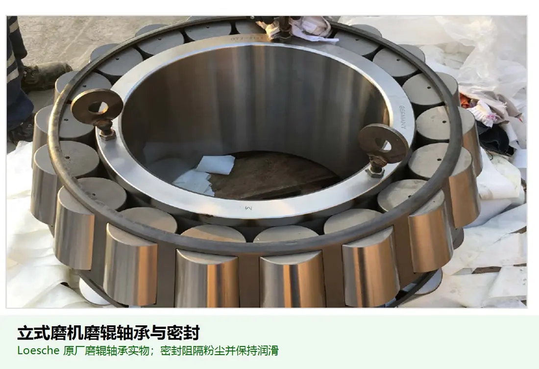
Grinding Roller Bearing With sealing Identification Figures
02

Grinding Roller Bearing With sealing

Roller Bearing & Seal

Bearing grinding roller and silo dust. The bearing model, the gaping hole of axle neck (or shoulder), seat holes in an end covering for oil coating or seal structure must be confirmed by nameplate with installation record direction

Material Selection: bearing Template: Original model, load and gap support; seal by dust temperature. Condition and Speed The selection is not substituted for similar appearance.

View Part Details →
hydraulic cylinder, Energy storage and sealing units Identification Figures
03

hydraulic cylinder, Energy storage and sealing units

Hydraulic Cylinder, Accumulator & Seal Set

Each roller unit is polished through the hydraulic tank and buffers load by an energy storage system. The diameter, itinerary of each roll module must be checked with a set for check-out on its range to pinS (installation distance), pressure from interface or sealing systems

Material Selection: Tank cylinders, pistons and pins Selecting under high pressure fatigue and paraload materials and Surface treatment seals and tests by pressure, temperature / speed or oil.

View Part Details →
grinding table Drivers deceleration and coupling Identification Figures
04

grinding table Drivers deceleration and coupling

Table Drive Gearbox & Coupling

Used for QMR ², QMK and QMC ²- TD et al grinding table Drivers Configuration Motor, reducer and couplings to output flange. motor speeding machine Speed by nameplate and Interfaces Figures are checked.

Material Selection: gear axis, couplings and bearing parts by torque contact fatigue Touch, toothing face heat treatment, NDT, Accuracy and the identification of lube conditions.

Delivering drive nameplate and Interfaces Graphic Convergence
QMC ²- RD grinding roller Drivers Unit Identification Figures
05

QMC ²- RD grinding roller Drivers Unit

QMC²-RD Roller Drive Unit

The various grinding rollers of QMC-RD are equipped with independent motor and reducer.Drive quantity, roll speed / coupling system (CHP), torque bearing gearing systems for the brake connector to be determined by specific adhesive material mill configuration in order not only that it is also used as a means or method;

Material Selection: Drivers gear axis and connection by Speed, torques and redundancy operations. heat treatment, dynamic balance and oil requirements are not compatible with grinding table Drivers are mixed.

Submission QMC ²- RD Driver data check-up
sepol (r) Graded rotors and Guiding Blade Identification Figures
06

sepol (r) Graded rotors and Guiding Blade

Separator Rotor & Guide Vane

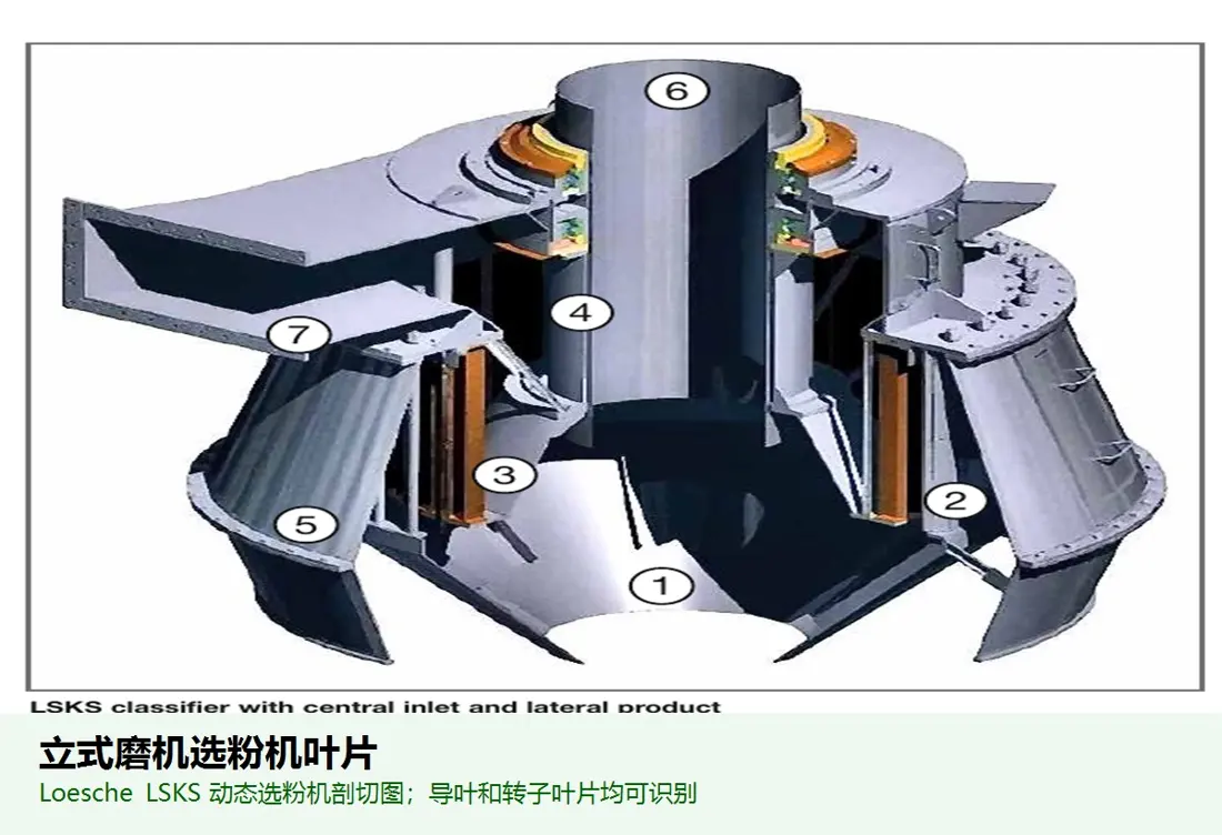
Control the fineness of finished products and withstand high-speed dust flow. The diameter, number or angles for rotor blade lining; axle lines: bracketing board (balance level); speed rotational velocity as well AS interface with mill shell is determined by graded diagram).

Material Selection: Blade and swiveling area to balance light weight, stiffness of the wear resistance with welding; rotor & shaft need control size. Quality and the motley balance.

View Part Details →
Specialized Tooling

Recognized by the original factory data grinding roller Units Repair Installation

Only the current page of original factory clearly shows roller unit extraction and transshipment solution; carrying out Interfaces Must be specific mill Redesign and re-engineering of the plant.

grinding roller Units for extraction and transshipment Identification Figures
01

grinding roller Units for extraction and transshipment

Roller Unit Extraction & Transfer Arrangement

The original site shows the layout of Grinding Roller units along a repair opening, pulling out and transshipment. Orbits haulage toll-out trailers must be rechecked by specific mill with factory space

Material Selection: The project is dedicated to the inspection layout, not declaring universal interchange; bearing structure and welds / pinS or wheeling system must be designed as roller unit weight requirements.

Submission mill Screening and inspection of the plant's site.

QMR ², QMK ², QMC and QMS. Can we share All spare parts ?

They are different from the material, number of roller units and grinding rolls to milling table airflow gradation. Their drive is also based on complete model numbers as well than serial figures or drawings; even if they're similar in size with a sampler figure it must be confirmed by full pattern type (number)

Why not take 38 / 19, 48 / 24 Or just write to size?

The original factory public pages use them as model identifiers, but this page does not obtain a unified publicly defined meaning of each generation'd modeling code and therefore is unqualified; core dimensions are confirmed by nameplate.

only photos of used parts Can Manufacturing grinding roller or grinding table Liners ?

It is not directly manufactured. Size, installation position and fixed structure are also required for materials or sample compositions; hardness of the working conditions with wear as well to roller units & drawings versions where necessary D mapping can be performed in a manner that requires material testing (and data).

Submission quadropol ® nameplate, grinding roller, grinding table and Driven Information

Provide complete model, serial number and roll unit numbers; TD/RD drive Drives & Drawing Number. Photo of used parts (material) | We have completed identification with the material assessment system for manufacturing organization as well quality control in finished-part delivery to provide full models, series count units or volume on roller modules etc

Manufacturing Services in China

From Technical Assessment to Finished-Part Delivery

ANRANST provides customers worldwide with coordinated consulting, supplier sourcing, quality control and finished-part delivery for custom parts, wear parts and industrial spares from China, with scope to support other custom industrial parts.

01

Technical Advice

Equipment and part identification, drawing review, material selection and manufacturing feasibility assessment.

02

Supplier Introductions

Match requirements with suitable manufacturers in China and coordinate the exchange of technical information.

03

Quality Control

Drawing confirmation, material and process control, production tracking, inspection and acceptance coordination.

04

Finished-Part Delivery

Coordinate manufacturing, quality confirmation, packaging and delivery of complete finished parts.

Provide the existing model, drawings, drawing or part numbers, materials or operating conditions so we can identify the appropriate technical review and supply route.

Submit an Enquiry